Category Archives: Retrocomputing

The Kim-Uno — a Kim-1 simulator

Ken Boak had mentioned on twitter that someone was creating a blinken-lights front end for the simh simulator of the PDP-8, called the PiDP-8, since you can power the entire thing from a Raspberry Pi. Very cool, but not quite available yet. What was available from Oscar is the Kim-Uno, a simulator for the old KIM-1 computer, a single board computer based upon the MOS6502 with a simple LED display and a whopping 1K of memory, first shipped in 1977 or so for about $245. The simulator is incredibly simple: a board, buttons, leds, and an Arduino Micro to drive it all. I went ahead and ordered one, just for kicks.

But you don’t actually need the hardware to play with this: you can get the code running on an ordinary Arduino Uno. So I did. It’s setup to run Microchess out of the box. Microchess is cool because it can play chess in less than 1K of code, and probably was the first commercial game software produced for hobbyist computers.

The Kim-Uno sketch is a little bit odd though. I’ve begun tinkering with it, and cleaning it up a bit. First of all, I thought it was confusing the way it tried to include the 6502 core emulation (written by Mike Chambers). It is written in C, and to merge it into the sketch required a bit of chicanery using ‘extern “C”‘ directives. Bleh, I renamed cpu.c to cpu.cpp, and cleaned that up. I fixed some forward declarations. I uncovered a couple of bugs by paying attention to compiler warnings. It won’t even come close to compiling on non-Arduino platforms, so I deleted lots of conditional definitions. And I generally just tidied things up. Along the way, I checked out the code that Oscar put in to scan the six digit display, which took a lot of pins. As is happens, I had an 8 digit display which used the 74HC595, which I had gotten working before using an interrupt driven display driver. I merged that code in, and now I had a hardware display like the Kim wired to my Uno. Probably refreshes more often than the original, but looks great!

When I get my code tidied up more, you’ll be able to download it on github. Stay tuned.

More musings of computers past: Popular Electronics, the COSMAC ELF

Screen Shot 2014-07-27 at 5.14.34 PMMy musings about my earliest memories of computers brought me back to 1976 and the appearance of the COSMAC ELF in Popular Electronics. I was only twelve, and probably had only the vaguest understanding of what such a machine could do, or why I might want one, but I remember reading these articles and it capturing my imagination. It probably laid the ground work for my continuing fascination with computers. Still, I never really developed any serious understanding of the architecture.

Now, when I stare at datasheets for the 1802 processor, it doesn’t seem particularly hard to understand, but it’s a pretty peculiar little chip. Wikipedia has a good introduction. It found some significant usage aboard satellites and space probes, including aboard the Galileo probe. You can get more documentation here. While the processor is not well known now, it actually generated significant interest until the 6502 hit the market.

I’ve just begun to dig around for more information:

Four articles that appeared in Popular Electronics on the COSMAC ELF
A JavaScript simulator the ELF

Addendum: There is a huge pile of RCA 1802 code on archive.org. Judging by the filenames, not all of it is 1802 related, but there is a ton of stuff.

Learning the ropes…

Over the past few years, I’ve expressed an interest in the AGC, or Apollo Guidance Computer. If you haven’t had the time to look at it, the Wikipedia page is good enough to get a brief overview, but if you want to dig deep, you can find all sorts of information and simulators.

I found myself looking back into it this week for two related reasons: one, the anniversary of the Apollo 11 landing, which I still remember, and because of a new argument that I’ve read (but won’t dignify with a link) that claims the moon landings were fake because the AGC could not have worked. But I must admit, he pointed at one bit of the AGC, its core rope memory which he claimed couldn’t work. I think the safer claim would be that he didn’t understand how it worked, but when I thought about it, I realized that I didn’t really know how it worked either. And that bothered me, so I thought I’d dig into a bit more.

Here’s a brief, high level introduction:


The basic idea is pretty simple, and relies on using ferrite toroids as transformers. Imagine that you have two wires going through a ferrite core. If you send a pulse in one wire, it will generate pulse on the other wire. This principle is used in all transformers, which may vary in the number of turns to step the voltage up and/or down by varying the number of turns through the toroid. You can generate a simple memory using this principle. This kind of memory is demonstrated admirably by SV3ORA who created a 70 bit ROM that serves as a decoder for 7 segment LEDS A pulse (or pulse stream, even better) on one of the ten input lines generates the appropriate set of output voltages to display the corresponding numeral on a 7 segment LED display. His webpage has some nice, easy to follow circuits, and a cute little video of it working.

But if you look at the diagram for the Apollo Guidance Computer, it looks a little different. It has a series of “inhibit” lines that weave in and out of the cores, in addition to some sense lines.

Screen Shot 2014-07-24 at 8.35.03 PM

The first description I found was around page 90 of this report, MIT’s Role in Project Apollo, Volume 3. But to be honest, I didn’t really understand it. Luckily, I found what appears to be a better description: P. Kuttner’s 1963 paper, The Rope Memory — A Permanent Storage Device. I still need to work through the details, but it makes a lot more sense to me. I begin to see how the address decoding works. I’ll ponder it a bit more, but it is beginning to make sense, and as it makes more sense, I see it for the clever bit of engineering it is. It was a remarkable bit of engineering in its day, and allowed densities of 1500 bits per cubic inch, including all the address decoding. Very cool.

Addendum: Hacker friend Jeff Kellem was unable to post a comment to this blog (got trapped by the spam filter, no doubt because of the high number of links, which normally indicate spam, but in this case indicates SCIENCE!) but he was kind enough to drop me an email with additional reading. I’ll reproduce it here:

You might find this July 1976 issue of BYTE magazine interesting:

Coincident Current Ferrite Core Memories
https://archive.org/stream/byte-magazine-1976-07/1976_07_BYTE_00-11_Core_Memories#page/n7/mode/2up

Also, maybe check out:

Magnetic Core Memory Systems
http://www.cs.ubc.ca/~hilpert/e/coremem/index.html

Ferrite CorePlanes and Arrays: IBM’s Manufacturing Evolution
http://ibm-1401.info/IBMCoreArraysIEEEMagnetics1969.pdf

And start with Volume 1, Issue 2 (May 1973) of Amateur Computer Club Newsletter, there’s a several part series titled “Core for Stores” in there:

http://www.smrcc.org.uk/members/g4ugm/acc.htm
http://www.smrcc.org.uk/members/g4ugm/ACC/Vol1-Issue2.pdf

Look forward to reading more about your exploration into core memory.

fyi.
-jeff

All very cool resources. All us old-timers probably remember Byte magazine (but to be honest, I didn’t recall that they had ever had an article addressing core memory) but I had never actually heard of the Amateur Computer Club newsletter. It’s deliciously old and homebrew. The description of core memories is great, it includes some of the drive circuitry that one would have built back in 1973. I’ll have to check it out further.

Addendum2: If you want to go to a lot of trouble (and per bit, a huge expense) to make a core memory that can be read by your Arduino, Wayne has a lot of advice and detail on his page.

Best thing at the MakerFaire: a relay computer that calculates square roots…

Long time readers here should know that I have a bit of a fascination with strange, retro computing devices. While I haven’t done anything significant in this area myself, I love to see them, and at yesterday’s MakerFaire, I saw Simon’s Relay Calculating Engine. I’ll let Simon explain it to you:


My own impressions: it’s brilliant. In the front it has a real presence. The cabinetry is beautiful. The interface is crazy in its retro feel: a rotary dial and metal pushbuttons, with Nixie tubes for output. There is even an awesome mechanical cam in the front that generates the two-phase clock signal. And the back is equally impressive, a maze of wiring connecting dozens of relays. Very cool.

Deconstructing the Classic Atari Game: Star Raiders

Gasp, I know. It’s been some time since I posted here. A combination of life and work events have conspired to sap me of my usual exuberant energy for the nerdy, geeky pointless topics that I usually like to post about here. But nerdy, geeky, pointless endeavors do continue (even if at a reduced pace) so I thought I’d post about one here that I’ve killed a few hours on.

I have fallen back into thinking about retrocomputing, not so much out of a sense of nostalgia, but because I was trying to understand the complex path that connected a 12 year old boy growing up in Oregon to the one who now exists. I think in no small part, I can draw it back to this game:

atari011

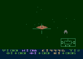
The classic 1979 Atari game Star Raiders. I’m pretty sure it was the second cartridge I bought for my Atari 400, right after Atari BASIC. Within it’s 8K boundaries, a first person space simulation was created. Not the boring, type “LRS” to get long range scan respresented in crude ASCII charts, but instead a visceral battle against the Zylon menace.

As much as I liked the game (and have played it a few times in the last few days, it still pretty much holds up) it also inspired me back then to learn how such highly interactive, real time games could be written. I got a copy of De Re Atari, and worked on learning about machine language programming, and how to manipulate POKEY and ANTIC to do my bidding. I used to say that the Atari was the last computer that I understood completely. Perhaps that was a little bit of bragging, combined with the humble realization that modern computers were far more of a black box than I felt I could understand.

But in the last couple of weeks, I thought to myself, “there must be some good programming hidden away in that 8K.” The scientist in me recognizes beauty not just in the final form of the organism, but in its constituent parts. So, I decided to see if I could take the raw ROM image of Star Raiders, and turn it back into an annotated chunk of source code. In theory, you could use this to make changes (I hesitate to say “fixes”, because it’s so brilliant) but really, it was just so I can learn something about how it works.

Luckily for me, modern tools have made this much simpler. I have a Linux box far more powerful than any computer I could have dreamed of back in the day, and retrocomputing pioneers have traveled this path already, and left tools that I could use along the way. I decided to use cc65, a freeware C compiler suite that can generate code for a variety of classic 6502 based systems. It includes da65, a disassembler that will take an “info” file which describes where the code starts and some machine specific labels, and then tries to disassemble the ROM back into assembly code. It more of less seems to default to the idea that the ROM is entirely code, and only inserts “.byte” assembly instructions when it can’t find a valid instruction at a particular location. By beginning at the known jump address, you can follow code and find areas where data instructions access tables and the like, and then use the .info file to describe block those out, slowly converging to more or less legible code. For instance, the decoded code that starts the cartridge looks like this:

; ----------------------------------------------------------------------------
CARTBOOT:
        lda     #$00                            ; A14A A9 00                    ..
        sta     SKCTL                           ; A14C 8D 0F D2                 ...
        sta     $66                             ; A14F 85 66                    .f
        sta     $62                             ; A151 85 62                    .b
        sta     $63                             ; A153 85 63                    .c
        lda     #$03                            ; A155 A9 03                    ..
        sta     SKCTL                           ; A157 8D 0F D2                 ...
LA15A:  ldy     #$2F                            ; A15A A0 2F                    ./
LA15C:  lda     #$FF                            ; A15C A9 FF                    ..
LA15E:  sty     $65                             ; A15E 84 65                    .e
        sta     $64                             ; A160 85 64                    .d
        lda     #$00                            ; A162 A9 00                    ..
        tax                                     ; A164 AA                       .
LA165:  sta     HPOSP0,x                        ; A165 9D 00 D0                 ...
        sta     DMACTL,x                        ; A168 9D 00 D4                 ...
        cpx     #$0F                            ; A16B E0 0F                    ..
        bcs     LA172                           ; A16D B0 03                    ..
        sta     AUDF1,x                         ; A16F 9D 00 D2                 ...
LA172:  sta     PORTA,x                         ; A172 9D 00 D3                 ...
        sta     a:$67,x                         ; A175 9D 67 00                 .g.
        inx                                     ; A178 E8                       .
        bne     LA165                           ; A179 D0 EA                    ..
        dex                                     ; A17B CA                       .
        txs                                     ; A17C 9A                       .
        cld                                     ; A17D D8                       .
        lda     #$02                            ; A17E A9 02                    ..
        jsr     LAE0F  

Seems like typical “begin the program” kind of stuff, the loop around LA165 is basically zeroing out a lot of I/O ports which control player missile graphic and audio, as well as lots of zero page memory starting around address $67. Not too exciting, but it gets you started.

A bit of poking (and review of old Atari programming manuals) made me realize that the system sets up the player missile graphics to be based from address zero. This means that the buffers for the player 0 will start at $400, for player 1 at $500, etc… Some further poking indicates that the display list (the list of ANTIC instructions that builds the display) begins at $280. I located a couple of data tables that contained a list of strings used in the game (with the first character in each having the high bit set). I located a fragment of a display list in ROM. I wrote a python program to generate a graphical version of each instruction (1s displayed as X’s, 0s as spaces) to see if I could locate some of the bit patterns from the game. This revealed that some font characters were defined starting right at the beginning of the ROM (mapped to address $A00) as well as the bit patterns for the TIE fighters, asteroids, etc…) in a variety of sizes:

B9B0:  X X
    :
    :X      X
    :X      X
    :X      X
    :X      X
    :X XXXX X
    :XXXXXXXX
B9B8:XXXXXXXX
    :X XXXX Xh
    :X      X
    :X      X
    :X      X
    :X      X
    :X     X
    :X     X
B9C0:X XXX X
    :XXXXXXX
    :XXXXXXX
    :X XXX X
    :X     X
    :X     X

That was helpful. But then progress began to slow a bit, and I wondered what other tools I could use. Back when I was teaching myself Atari 2600 programming, I found the Stella simulator to be absolutely key: it had an awesome single step debugger that I used to work out many a difficult chunk of code. Without any real research, I settled on using the atari800 simulator from sourceforge. A bit of digging uncovered that hitting F8 dropped you into a monitor. Not as sophisticated as the Stella one, but still quite helpful. For instance, if you type “DLIST”, you can get the currently active display list. During the “attract mode” of the game, you can break and find that the current display list is:

0280: 2x 8 BLANK
0282: LMS 1000 MODE D
0285: 10x MODE D
028F: 4 BLANK
0290: LMS 0D1F MODE 6
0293: LMS 12A8 MODE D
0296: 81x MODE D
02E7: JVB 0280

This is pretty helpful (although it’s probably gobblety-gook to most readers). Reading from top to bottom, it says that the display has 16 scanlines which are blank, then starts rendering with mode D (which is a 160 pixel resolution, 4 color mode, where each dot is 2 scanlines high). The LMS indicates that the graphics memory will start at $1000. There are a few more lines like that, then some blank lines followed by a mode 6 line (which is a 20 character display, 8 scanlines high). Then some more lines of Mode D (resetting the memory buffer to the appropriate address). The mode 6 line draws characters from the buffer beginning at $0D1F, which I had not identified in code anywhere. That presented a clue to me, enabling me to spot other useful chunks of code.

I’ll keep plodding away at this, it is kind of like working on a crossword puzzle. Each little bit you uncover allows you to understand more. Stay tuned.

Chris Fenton’s Amazing Electro/Mechanical computers

I remember reading about Chris Fenton’s homebrew Cray, which was impressive enough. It was implemented on a Xilinx Spartan-3E FPGA board, and eventually he got a Cray assembler written. It also is neat, because it looks like a tiny Cray:

img_2311

But I wasn’t too interested in actually building one. But the gods of Internet surfing sent me back to his website today and I found two new projects of exceeding awesomeness:

The FIBIAC – an electromechanical computer


And the even more amazing, purely mechanical Turbo Encabulator:


As my only “value added” link, Chris makes reference to a book entitled “The Mechanism of Weaving”, which detailed the function of the Jacquard looms that were the predecessors of punch cards and early mechanical computers. His edition was published in 1895, but it turns out you can get an online copy from the Internet Archive. Very neat.

Resources on the IBM 1401

Okay, I was trying to find more information about the IBM 1401, and the bitsavers website again came to the rescue. If you surf over to to their directory of IBM 1401 information, you can find some nifty references. One of the most useful references is 1962 manual Programming the IBM 1401. A somewhat less conversational but perhaps more complete reference is A Guide to 1401 Programming. Another useful reference is this 1401 Data Processing System Reference Card. Armed with this information, can it be long before I write my first 1401 program?

Well, it might be, but who knows?

An IBM 1403 font…

A few days ago, I was playing around with my Raspberry Pi, trying to get a new, freshly compiled version of the TOPS-10 7.03 monitor running. I was having some difficulty with it, as it appears that a bug had crept into the code that simulates the DZ11 serial ports as telnet connections, and I could no longer login from “remote” terminals. While I was grumbling about that patiently awaiting a fix to appear on the simh github server, I started thinking about other computers. (Long time readers may remember that I suffer from occasional bits of technological nostalgia, having previously written an emulator for the PDP-1 so I could play SpaceWar! and written all sorts of fun code for the Atari 2600.)

So, I started looking into the IBM 1401.

Recently, the Computer History Museum completed a restoration project to bring an IBM 1401 back from the dead. Actually, they have now have two. Each weighs about 4 tons, and the 1401 was quite possibly the most plentiful computer back in 1964 when I was born.

It’s a really odd machine. You can read more about it here. It was mostly implemented using diode-transistor logic (now you know where my recent poking at DTL logic came from). It had core memory, with up to 16Kbytes! The first machines where announced in 1959, and construction ceased in 1971 as the IBM/360 architectures became dominant.

But all this is really an aside. I was thinking about my DEC experience, and started thinking about the line printers we had back then. Unlike the quiet woosh of today’s laser printers, these where heavy, loud, mechanical monstrosities, but they were fast. They could spew out a printed sheet of green bar paper in about six seconds, and if you had lots of form feeds, could eject 75 inches of paper each second. I remember seeing someone do that at the University of Oregon (probably on a DEC LP20) and you could visibly see the stack of fanfold beneath the printer drain away).

I suspect that the printer hooked to our DEC-1091 at the University of Oregon in the early 1980’s might have been an LP20, but I got hooked on researching the technology with some judicious googling, and found references to the IBM 1403 printer, which was commonly paired with the IBM 1401. I ran across this page about the IBM 1401 restoration, which included the following example print sample:

1403Font-

I liked it. So, on Twitter, I idly mentioned that I wondered if anyone had created an IBM 1403 inspired font.

And it turned out that a hacker friend of mine with diverse interests, Jeff Kellem (@composerjk) heard my call. Among his interests and talents is typography and font design. Jeff took some print samples and started working on a 1403 inspired font. While he’s not ready to release yet, the preliminary results look awesome:

sample-text-listing2-12pt-clip-perspective-small

What is even cooler is that Jeff wrote up some notes on his blog about how he did it, as well as some additional inspiring links about the 1401 restoration project. Great stuff, and thanks to Jeff!

On Relay Computers…

I share an interest in old computing technology with several of my friends and readers. An interesting sub-topic within this vast area is the world of computers based upon relays. In the last couple of days, I found cool links to two different relay based computing projects, so I thought I’d pass them along.

First is Jon Stanley’s Relay Computer Two. Consisting of 281 relays, it boasts an 8 bit data bus and a 16 bit address bus. His website gives the kind of dense, technical information that I like to see from a project like this. You’ll see how he implements adders (using Konrad Zuse’s design which constructs a one bit full adder out of two 4PDT relays). Very neat. Lots of cool details. It clanks along at less than 30 cycles per second. Yes, it uses solid state memory (as almost all amateur reconstructions do, it’s simply to expensive to do otherwise) but the result in a clicky, clanky marvel. Check it out (and make special note of the enormous capacitor in the power supply):


Then there is Rory’s awesome series of relay based computers, culminating in the TIM-8. There are all sorts of awesome laudable features in this build. He didn’t want to “cheat” and use solid state memory, so he struggled to find solutions. He ends up storing programs on paper receipt tape as a series of black and white lines which provide control signals to the rest of the computer. These are then loaded onto a motor driven spindle and read by a series of phototransistors (I think, not clear). The tape is rewound and replayed during program execution. Very cool. He also constructed his own solid state memory out of capacitors, with a density of about 9 bits per cubic inch. Very, very cool. Here’s one of his videos, but search around on his site, he has more: