Some Document Scanner Links

December 13, 2009 | General | By: Mark VandeWettering

I love books, and I love the fact that technology is becoming increasingly easy to get books digitized and distributed online. Several years ago I got a copy of Johnson’s Natural History that I’d love to have digitized, but as yet haven’t located anyone whose willing to do it for me. But today, I found a couple of interesting links that suggest with a modest investment, I could make a book scanner of my own. Here are some links to some projects that might be useful:

diybookscanner.org
bookliberator.com

KL7R’s HW-8 DSB modification…

December 13, 2009 | Amateur Radio | By: Mark VandeWettering

G3XBM pointed out silent key KL7R’s modification of a Heathkit HW-8 to do double sideband voice. It looks pretty straightforward, and would be an interesting modification. My own HW-8 isn’t exactly pristine, but I am torn between keeping it in its native state, and performing a modification to make it more versatile. Bookmarked for later.

DSB with a Heathkit HW-8

An Active Filter Design

December 12, 2009 | Amateur Radio, electronics | By: Mark VandeWettering

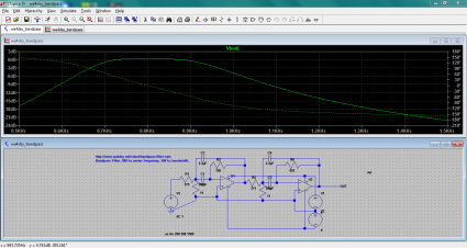
Eldon, WA0UWH pointed out WA4DSY’s website that features an active filter design applet. I was just waking up this morning, so I thought I might give it a try. I used LTSpice’s universal op-amp node, and wired it for positive and negative voltage feeds. I specified a 2.2uH value for the caps, and a 800hz center frequency, with a bandwidth of 300hz. It is just a two pole filter, so you shouldn’t expect much, but I suspect it would be useful. I am tempted to try to adjust the resistor values to nearby standard values, and see how it looks, but I think I’ll need coffee before I do that.

2009-12-12_0932

Addendum: a little poking around, rounding the various values to their nearest 10% values resulted in a filter with approximately the same shape, but which had decreased gain in the bandpass region (roughly 3db down from the original). I suspect at the very least, you could compensate by adjusting the overall gain of the filter.

The FDIM 2010 QRP Challenge: a good personal challenge?

December 11, 2009 | Amateur Radio | By: Mark VandeWettering

I’ve never attended Dayton or FDIM, but I am thinking that perhaps I will soon (hopefully this year). An affiliated event is the Four Days in May: the QRP event for the QRP Amateur Radio Club International. They are hosting a building contest this year:

QRP Amateur Radio Club International – The FDIM 2010 QRP Challenge.

The long and the short of it is to build a complete QRP transceiver that has only 72 parts. This doesn’t seem too hard except the receiver is specified as being single signal, and you are only allowed one IC in the radio. Seems like an interesting project. It’ll give me something to think about while I’m on the airplane this evening.

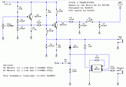
Addendum: An example of a transceiver that would not qualify would be the Pixie II.

pixie2-schematic

By my count, the Pixie II has 24 parts, and implements a complete transceiver, but it’s a simple direct conversion receiver, and therefore isn’t single signal. Still, an interesting launching point.

Addendum: Steve Weber’s AP-80 looks like a much better radio, but again, I think it’s a simple direct conversion receiver.

Regarding comment spammers…

December 10, 2009 | Rants and Raves, Stupidity | By: Mark VandeWettering

It’s been quite some time since I had a decent rant on this blog, and I didn’t sleep well last night, and I am feeling a tiny bit grumpy, so pretty much anything will set me off on a rant. I figure I may as well get it off my chest now, then I can get down to work.

Comment spammers, you guys really suck.

I enjoy having a blog. I don’t try to support it with ads. It’s a flat out expense: my $8 or $10 a month buys my hosting, and I can run WordPress and I’m really quite happy. To date, I’ve made 3234 posts (this will be 3235) and have approved 1,588 comments in the six years or so its been going on. For everyone who has found anything of genuine interest here, I thank you for checking it out, and occasionallly leaving your genuine comments.

But here’s my reality: since October, 2006 (the earliest date I have good statistics for) my blog, the spam filter Akismet that WordPress ships with has caught 202,756 spam comments. In some sense, these aren’t the worst problem, since they are automatically caught and routed directly to the bit bucket. Nobody ever sees these posts. They don’t generate even a single click through. But the ratio of legitimate comments to fake comments is about 200:1 or so. That means that the vast majority of the actual cost in terms of bandwidth that I see is likely to go to these comment spammers. If we could eliminate spammers, there would be lots more, lots cheaper bandwidth available for us all.

But another kind of comment spam is currently sneaking past my filters occasionally. If you have no links inside your post, but merely use the ability to specify a URL with your ID, it will often make it through my spam filter and get posted. Many of these “comments” contain empty platitudes like “Wow, this is a great post, I’m bookmarking your site for later.” Who are they kidding? It’s annoying to have to read this kind of banal crap, whose only purpose is to send you to some overseas pharmacy where you can get drugs for that “special part of the male anatomy”.

Bleh! Comment spammers are going to a huge amount of effort to annoy us all. Can’t we all just rally with pitchforks and make the world a better place?

I now return you to your regularly scheduled morning.

Visible Storage Event @ the Computer History Museum

December 9, 2009 | General | By: Mark VandeWettering

If you haven’t visited the Computer History Museum in Mountain View, California, then this weekend might be a good time to go. On Sunday, they are having a special event celebrating their “Visible Storage” exhibit. This is a terrific exhibit which is going to be closed after December, in preparation for a new exhibit which I hope will be as exciting as this one. Visible Storage consists of literally hundreds of different machines and artifacts from computing history, from old style Napier bones, to the bicycle sprocket computers of Lehmer, to the Enigma machine, ENIAC, Johnniac, personal computers of every make, Crays, hypercubes, Connection Machines… A fascinating collection. If you haven’t had the chance to go see this, make sure you do before it’s gone.

Computer History Museum – Events

Photosynth of my office…

December 9, 2009 | General | By: Mark VandeWettering

Want to know what it is like to be me? Here is a photosynth of my office at Pixar Animation Studios. It’s my first try, combined from around 170 individual photographs. Let me know what you think.

Addendum: You’ll probably need to be running Windows to view this.

Bandpass Filters

December 8, 2009 | General | By: Mark VandeWettering

Just some more playing around. I surfed to the following page, looking for bandpass filter designs, such as might be used at the input stage of a radio.

Bandpass Filters.

I took the 30m version of their filter, and created it in LTSpice, and did an AC analysis. As you can see, it’s not bad:

2009-12-08_1947

The only real problem for it is that it has about 6.5db of insertion loss: all signals are attenuated by this, even signals in the pass band. I haven’t quite figured out how to model the version of the same filter which has a transformer at each end yet. I’m also unsure how the Q of the inductors will enter into the evaluation of the filter. More later.

Tank Circuits…

December 7, 2009 | electronics | By: Mark VandeWettering

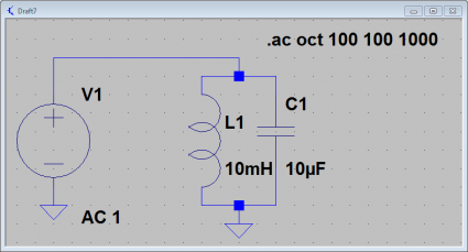
Okay, time to work my way through some more complicated (but stll simple) examples. First of all, let’s consider a simple parallel LC circuit. Here is one with a 10uF capacitor and a 10mH inductor in parallel with an AC source:

2009-12-07_2156

We can compute the resonant frequency using the classic formula:

          1
f = ------------
        __   ___
    2.0 || \/L C

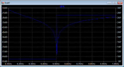
Plugging in our values for L and C, we end up with a resonant frequency at approximately 500 Hz (more precisely, about 503 Hz). So, let’s use LTSpice to analyze the circuit using AC analysis, sweeping the frequency from 100Hz to 1000Khz. If we look at a graph of the current draw through the voltage source from this parallel LC circuit, we see the following:

2009-12-07_2157

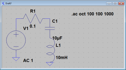
The parallel LC circuit’s current draw drops to zero at the resonant frequency. It’s impedance goes to infinity at the resonant frequency, the tank doesn’t draw any current. Let’s compare it to the same circuit, but with the elements placed in series instead of in parallel. We’ll add a very tiny resistance as well.

2009-12-07_2224

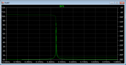
This circuit also resonates at the same frequency, but with radically different behavior. Let’s graph the current in this circuit:
2009-12-07_2257

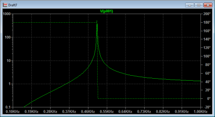
The currents through the circuit are huge, and peak at the resonant frequency. There are similarly huge voltages that appear across the capacitor.

2009-12-07_2202

All this is pretty basic stuff. I apologize for boring people with this, but I’m learning lots about using LTSpice by doing these basic exercises. It’ll eventually pay off by having a deeper understanding about how these circuits work.

Addendum: I was inspired by this chapter on resonance from Tony Kuphaldt’s second book on AC electric circuits. These books are part of the Open Book Project, and are available for free download. I’m gonna make good use of these.

Power Transfer Math

December 7, 2009 | Amateur Radio | By: Mark VandeWettering

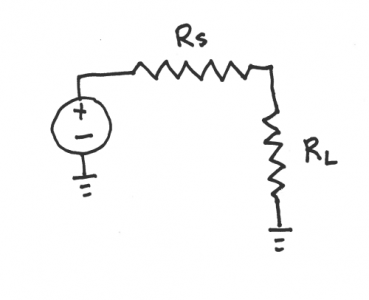
As I might have mentioned, I am trying to teach myself a bit about electronics and radio design. I find the problem with being self taught is that often you read something, and it doesn’t seem clear to you why it should be so, and you uncover the basic lack of understanding that you have to go back and fill in before the later material makes sense. This happened to me while I was trying to work through some more amplifier designs, and I realized that I had a basic misconception about how impedance matching actually worked, and this was perhaps even more basic, and could be illustrated with a simple circuit, consisting of a voltage source, and then in series a source resistance RS and a load resistance RL. The question is given an RS, what value of RL maximizes the power dissapated in the load RL?
power

Well, it’s not really too hard to figure out. First, we can determine the total current going around the loop. For a voltage V, the current is simply:

       V
I = -------
    R  + R
     S    L

From this we can easily determine the voltage drop across RL:

      R  V
       L
V  = -------
 L   R  + R
      S    L

And, since we know the current through and the voltage across the resistor, we can determine the power as their product:

            2
        R  V
         L
P  = ----------
 L            2
     /R  + R \
     \ S    L/

When is power maximized? Well, we can differentiate the power equation with respect to RL, and we get:

                           2
dP         2         2 R  V
  L       V             L
--- = ---------- - ----------
dR             2            3
  L   /R  + R \    /R  + R \
      \ S    L/    \ S    L/

Setting this equal to zero, and solving for RL, we find that a maximum occurs where RL equals RS, in other words, power is maximized when the source and load resistances are matched. The total disappated by RL is then:

      2
     V
P  = ---
 L   4 R

Thus, if we had a load of 50 ohms and a voltage source of 12 volts, we’d end up with a maximum power of 720 mw.

Addendum: As a double check, the power passing through both resistors is V^2 / 2R, which would have been 1.44 watts, and obviously since both resistors are the same, the power is evenly split between the two.

Addendum2: I forgot to mention what I was confused about. It’s not really this (which occurs in DC circuits) but the corresponding circuit which occur in AC circuits with complex impedances. I’ll work through this later.

Addendum3: Hmm. Subscripts and superscripts seem to not work right with this theme. I’ll fix it.
A Half Wave Filter in LTSpice

December 6, 2009 | General | By: Mark VandeWettering

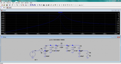
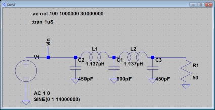
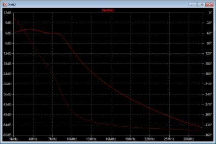
On page 3.4 of Experimental Methods in RF Design, they have a little side bar about a particularly simple form of harmonic filter that I thought I would try to analyze in LTSpice. Here’s a screen dump of the filter I designed to operate around 7.0Mhz.

2009-12-06_2205

It’s really pretty simple to figure out the value of the various components: if the load has a reistance of Rload, then the inductors both have the same reactance XL in ohms. The two outside capacitors also have that same reactance, while the inner one has twice the value. Combined with the formulas for the reactance of an inductor and capacitor, it isn’t hard to figure out the values.

XL = 2.0 * π * frequency * L
XC = 1.0 / (2.0 * π * frequency * C)

Performing an AC analysis, you can get the frequency response. You can see that this filter actually passes the design frequency at 0db, but is significantly attenuated at 2x the frequency, and even more so for higher multiples. Here is LTSpice’s simulation.

2009-12-06_2204

Ham radio without a radio?

December 6, 2009 | Amateur Radio | By: Mark VandeWettering

OZ9AEC shows how you can use free software and web-based radio receivers to decode amateur digital communications. Very nifty. I tried this myself using WebSDR, and it worked great.


httpv://www.youtube.com/watch?v=GB9Ed02Vhr8

Gaining experience with LTSpice…

December 5, 2009 | Amateur Radio | By: Mark VandeWettering

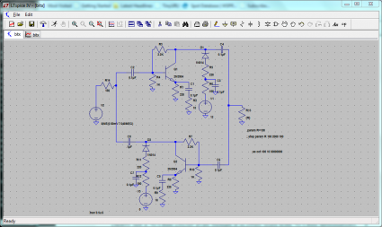
So, for fun, I entered the circuit for the bidirectional amplifier used in the BitX20, and did some basic simulation. You can see it in the image linked below. I was trying to figure out how to instrument the schematic so I could determine the input and output impedance (and eventually things like return loss as well). Still puzzling over stuff like this. But the circuit is pretty straightfoward. I may have to build this amplifier, just for amusement.

bitx

Addendum: If you don’t know what a BitX-20 is, you can find out lots by googling around, perhaps beginning with Farhan’s original page. If you check out his schematic, you’ll find three copies of this bidirectional amplifier.

The Christmas Season is upon us…

December 5, 2009 | General | By: Mark VandeWettering

Well, I spent the morning raking leaves in my front yard, and then went over to Target and got some new LED lights for our Christmas tree, and also got a new wreath. In keeping with our desire to decorate, I’ve changed the theme of my blog from its normal spartan whiteness to this holiday monstrosity of cheer. Enjoy it while it lasts, and best wishes to you all this holiday season.

Simple Temperature Sensing IC

December 3, 2009 | Amateur Radio, electronics | By: Mark VandeWettering

A couple of projects that I’ve been pondering could make use of a little temperature sensing chip. Microchip makes this little gadget, the MCP9700A, which could be quite useful, and can be had for about $.35 from Digikey or Mouser. It comes in a simple TO-92 package, or smaller surface mount chips.

MCP9700A-E/TO-ND.