Tag Archives: Arduino

Template Program that uses a DS3231 RTC to wake up an Arduino

So, my idea is to use a cheap but reasonably accurate RTC chip module based upon the DS3231 chip to periodically wake a sleeping Arduino. I tried getting it working yesterday, but had little luck. I don’t know whether it was Bailey’s insistence on being petted or simple sleep deprivation, but it eluded me yesterday. Today, I decided to go about it more methodically, and with the help of my trust Rigol DS1102E oscilloscope, I made sure that the module was generating a proper pulse stream, and eventually stumbled on the right order of operations to get this working.

For the purposes of this demonstration, I’ve programmed ALARM_2 to trigger every minute (it fires when the seconds are 00) and then programmed ALARM_1 when the trigger matches 30. This means that the interrupt fires to wake up the Arduino every 30 seconds. When it wakes at the moment, it doesn’t do anything particularly interesting: it just prints the time and temperature (which doesn’t seem right, so I’ll have to dig into why).

Anyway, the code isn’t particularly complex, but there were a few details to work through, and it might be useful in the future. It will require a tiny bit of extra work to (say) trigger every 5 minutes. You basically will have to use the setAlarm function to set the alarm to go off at a particular point in the future, and when that alarm is triggered, then tell it to trigger again 5 minutes in the future. I don’t foresee any trouble.

Anyway, here is the code:

#include <LowPower.h>
#include <DS3232RTC.h>        // https://github.com/JChristensen/DS3232RTC
#include <Streaming.h>        // http://arduiniana.org/libraries/streaming/
#include <Wire.h>

/*  _   _               
 * | |_(_)_ __  ___ _ _ 
 * |  _| | '  \/ -_) '_|
 *  \__|_|_|_|_\___|_|  
 *                      
 * Some simple code to test the idea of using a DS3231 module's "alarm"
 * functions to periodically wake up an Arduino which is in POWER_DOWN
 * mode so that it will do something interesting.   This is really just
 * a skeleton now, but will serve as an outline for a more advanced sensor
 * sketch.
 *
 * Written by mvandewettering@gmail.com
 */

const int wakeupPin = 2 ;

volatile int woken = 0 ;

void
wakeUp()
{
    woken = 1 ;
}

void
setup()
{
    pinMode(wakeupPin, INPUT_PULLUP) ;
    pinMode(LED_BUILTIN, OUTPUT) ;

    Serial.begin(115200) ;
    delay(50) ;
    Serial.println(F("WAKING UP...")) ;

    Serial.println(F("I2C set to 400K")) ;
    Wire.setClock(400000) ;

    setSyncProvider(RTC.get);   // the function to get the time from the RTC
    if(timeStatus() != timeSet)
        Serial.println("Unable to sync with the RTC");
    else
        Serial.println("RTC has set the system time");

    Serial.print("::: INITIAL TIME ") ;
    printDateTime(RTC.get()+7UL*3600UL) ;
    Serial.println() ;
    delay(50) ;

    // initialize the alarms to known values, 
    // clear the alarm flags, clear the alarm interrupt flags
    // ALARM_1 will trigger at 30 seconds into each minute
    // ALARM_2 will trigger every minute, at 0 seconds.
    RTC.setAlarm(ALM1_MATCH_SECONDS, 30, 0, 0, 0);
    RTC.setAlarm(ALM2_EVERY_MINUTE, 0, 0, 0, 0);

    
    // clear both alarm flags
    RTC.alarm(ALARM_1); RTC.alarm(ALARM_2);

    // We are going to output the alarm by going low onto the 
    // SQW output, which should be wired to wakeupPin
    RTC.squareWave(SQWAVE_NONE);

    // Both alarms should generate an interrupt
    RTC.alarmInterrupt(ALARM_1, true);
    RTC.alarmInterrupt(ALARM_2, true);
}

void
loop()
{
    // The INT/SQW pin from the DS3231 is wired to the wakeup pin, and
    // will go low when the alarm is triggered.  We are going to trigger
    // on the falling edge of that pulse.
    attachInterrupt(digitalPinToInterrupt(wakeupPin), wakeUp, FALLING) ;

    // Go into powerdown mode, waiting to be woken up by INT pin...
    LowPower.powerDown(SLEEP_FOREVER, ADC_OFF, BOD_OFF) ;

    // For now, let's just ignore transitions on this pin...
    detachInterrupt(digitalPinToInterrupt(wakeupPin)) ;

    // We have to clear the alarm condition to make the pin go back to
    // the high state.   I'm clearing both of them, because we are 
    // triggering every 30 seconds (in this example)
    RTC.alarm(ALARM_1) ; RTC.alarm(ALARM_2) ; 

    // Now, we can do whatever we want to do.  For now, we just get 
    // the current time and the temperature (which doesn't appear to 
    // work, and will be what I'm investigating next)

    printDateTime(RTC.get()+7UL*3600UL) ;
    Serial.print(" ") ;
    Serial.println(RTC.temperature()) ;
    delay(50) ; // allow serial to drain, otherwise we'll go to sleep
		// before the buffer empties.
    
}

void 
printDateTime(time_t t)
{
    Serial << ((day(t)<10) ? "0" : "") << _DEC(day(t)) << ' ';
    Serial << monthShortStr(month(t)) << ' ' << _DEC(year(t)) << ' ';
    Serial << ((hour(t)<10) ? "0" : "") << _DEC(hour(t)) << ':';
    Serial << ((minute(t)<10) ? "0" : "") << _DEC(minute(t)) << ':';
    Serial << ((second(t)<10) ? "0" : "") << _DEC(second(t));
}

If it turns into something more interesting, you all will be the first to know.
Baby steps with the DS3231…

Last night, I did a small amount of work on two projects.

I applied some Wood Bondo to a couple of bad defects in my garden bench project. I hadn’t used it in a while, and forgot what a pleasure it was. Sanding should be finished up shortly and I’ll definitely have it painted and finished this weekend.

The other thing I worked on was trying to prototype the main control loop of my IoT sensor project. Since I got the basic radio hookup done last night, I thought I would work on a slightly different issue.

My recent musing have been concentrating around reducing the power consumption of these boards. The way that is normally achieved is by putting the processor to sleep, effectively telling it to halt the main processor for a predefined amount of time. Then, either in response to a timer event or an external interrupt, the processor can wake up, read all its sensors, and log it to a local SD card or transmit the measurement wirelessly before going back to sleep.

Some microcontrollers have elaborate timing modules that can run while the main processor, but that is not the case for the Arduino. It just has a single “watchdog” timer that can serve to wake the processor back up, and it is relatively inflexible: it can only be set for a small set of intervals, the maximum length of which is eight seconds. It’s also not particularly accurate, since it is clocked by an RC based internal oscillator that operates at 128Khz. You definitely can try track time this way, but it seems a bit complicated and a little messy

As it happens, I have a fair number of DS3231 clock modules lying around. The specifications have an accuracy of ±2ppm from 0°C to +40°C , which translates to an accuracy of about one minute per year. I could live with that.

The DS3231 also includes an alarm module. This enables you to program two alarm registers with times that will trigger the alarm when matched. There are two registers (ALARM_1 and ALARM_2) and you can query whether either has been triggered, or you can configure the the chip to toggle the SQW output pin low when the alarm goes off. I found this primer to be pretty helpful. What was not helpful was that my cat Bailey kept on jumping into my lap while I was trying to concentrate, so while I managed to get the basic “polling” based code to work, I couldn’t quite wrap my head around getting the sleep mode and interrupt stuff to work. I think that tonight I’ll pull out my oscilloscope to ensure that the proper signals are being generated by the board, and then at least narrow my confusion to where I can hopefully eliminate it.

In the mean time, I’ve been spending some of my spare time reading all the tons of useful information on The Cave Pearl Project website, including this awesome collection showing how build their Pro Mini Data Logger. The accompanying video play list shows lots of tiny bits of cleverness in how they prep the various boards and attach them together in a clever way to build a nifty little datalogger for less than $10 in parts. Well worth your time to watch.

Brain Fail: How to waste several hours trying to get an NRF24L01+ working on an Arduino…

I must admit to a certain amount of jealousy about people who demonstrate an ability to start and finish large projects. Granted: I have a full time job and that job is not tinkering with my little home projects. But when I see someone construct a complex prototype of electronics, a large piece of woodworking, or simply the ability to regularly author content on Youtube or their blog, I feel like a bit of a slacker.

It’s not that I don’t actually get things done. I do. I just always feel like my progress proceeds at a slower pace than I would like, or even seems reasonable.

Anyway…

I’ve been thinking more in the line of creating some very small, very battery stingy IoT sensors for… well… just because really. This is an extension of the tinkering I did with my prototype solar setup, as well as some work to logging data to a microSD card that was inspired by thecavepearlproject.org. I also liked some of the ideas present in Jeremy Cook’s “Standard Nano” setup.

So… in my head I have a nebulous goal to create a new little project to explore building some prototype IoT modules that have the following characteristics:

  • Cheap. It’s not hard to build capable modules without any regard to budget. I would like the price of each module to be around $5.
  • Re-usable. Much like Cook’s “Standard Nano”, I want to be able to have a basic core around which I could create a variety of sensors.
  • Low power. I want the the modules to be able to be powered by batteries, and they should for a time measured in months. Making a unit which is solar powered is possible, but probably interacts with the “cheap” requirement, and there may be situations where solar power is inconvenient.
  • Wireless. The Cave Pearl Project has many sensors which record data to an SD card, but I’d like to have it sending live data back to a server where I can interact with the nodes in real (or at least near real) time.

I’m not the first person to think of this kind of thing, and the path seems pretty obvious from a hardware perspective.

  • Arduino Pro Mini 3.3V 8Mhz costs about $2.45, and can easily be adapted to lower power consumption by disconnecting the power LED and (perhaps) doing the same for the power regulator.
  • NRF24L01+ Wireless Transceiver Module costs about $1.25 each.
  • Sensors. Some are likely to be free, or every nearly so. You can do temperature lookups with cheap components or even none at all. Sensors that detect light, voltage, current, or things like reed switches are often very inexpensive.
  • Batteries.
  • Containers. (I like to use small lunch style boxes from Dollar Tree).

I think that we’ll be a bit above $5, but certainly less than $10 per unit.

So, I thought I’d do a proof of concept. Using the Arduino Pro Mini for the final sensors makes sense, but it’s easier to prototype with breadboards and a couple of spare Unos that I have lying around. I dusted them off.

You have to be a bit careful using the NRF24L01+ boards with 5V. While the inputs are 5V tolerant, you have to be sure to just pass 3.3V to the module. Every reference I found on this module makes sure to mention this. And this is where I got into trouble.

You see, I had some cute little adapter boards lying around to make it easier to hook these up to 5V Arduinos. They bust all the pins out into a straightforward layout that is more clearly labelled, and include the decoupling capacitors that make the modules run more stably. I had them on hand, so I thought I’d give them a whirl.

So, I hooked them up, loaded up the the “scanner” example sketches that came with the RF24 library I chose, and…

It printed out data, but it was essentially all zeros.

Double checked the wiring. Triple checked. Still nothing.

Came back the next day. Was it a bad module? Swapped it out. Still the same. Swapped out the Arduino. Nope, still the same.

Damnit, what was it? Should I get out the scope? Was I an idiot who just didn’t wire things properly? Was the library just crap? I mean, it didn’t appear to actually try to ensure that the SPI bus was communicating properly. You can just disconnect power to it (or not power up the module at all) and it would all be the same…

I had something in the neighborhood of three or four hours into it. I was thinking about the plan for the next day’s testing as I prepared for bed. I was just lying down and pulling in the covers, and it hit me… I stood up, walked downstairs, made a small change, and fired up the module and it worked perfectly.

The problem was stupid. You see, I was using the adapter boards. They have a 3.3V regulator on board. Of course, you need a bit of headroom above 3.3V to have it generate that voltage. After all the dire warnings from my reading about being careful to hook up the modules to 3.3V, I had passed 3.3V into the VCC pin on that module. That feeds into the regulator, but without sufficient headroom to hold 3.3V to power the module.

I moved the VCC of the adapter module to 5V, and it fired right up.

Dumb dumb dumb dumb dumb. And hours wasted.

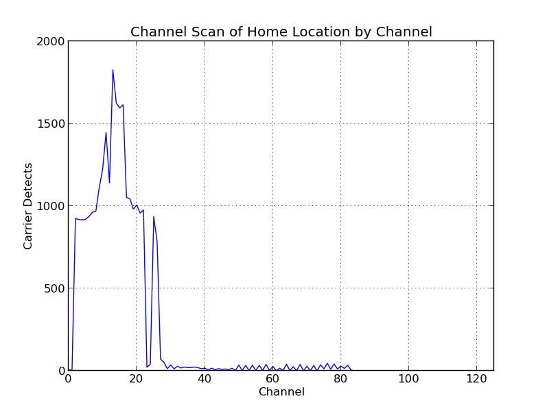
Anyway, I got it working, and then did a scan for a half hour or so to figure out what channels are likely to be free for use. It was pretty apparent that most of the 2.4Ghz activity in my house is concentrated down at the bottom edge of the band even scanning by eye, but I summed up all the carrier detects that it logged during that time, and with a little Python/matplotlib magic:

Any channel up above 85 or so should be smooth sailing.

Oh well, that took me longer than I would like, but I have it working. Next step will be to get one of these NRF24L01+ modules working on a Raspberry Pi. My idea is that all sensors should send information to the Pi, and the Pi will inject it as messages to my MQTT broker for further processing. Then, I can process events with Node Red.

Stay tuned, and hope that I’m not so dumb at every step of the way.


Arduino Mini, using Micro Amounts of Current…

Last night, the weather was pretty rainy. I woke up a couple of times during the night (once, when my little cat friend Bailey decided to check my breathing and started head butting me around 4 AM) and heard a lot of rain falling on the roof. When I woke up, it was fairly wet outside. I made myself a cup of tea and settled into check messages and email…

And the power went out.

Sigh. I could have used my phone and the cell service, but instead, I just spent a few minutes thinking.

Like about my battery backed up temperature/pressure sensor I had running in the garage, which is battery backed up. And since it sends its data to the MQTT server at io.adafruit.com, it should wo…

Oh, except of course my network is down.

It got me thinking that perhaps logging data to a local SD card isn’t actually the worst idea. Maybe once a day or so, it could wake up and send all the backlogged data to the server, but continue to log data locally.

And while I could use a microcontroller like the ESP8266, those things take a lot of current. Maybe it was time to look into something else that could be efficiently powered down and then only power up the remote peripherals (like a radio) when needed. And instead of using any kind of fancy charging circuit, maybe I could make something that is just powered from either Alkaline batteries with a run time of maybe a year.

As it happens, last night I found a couple of Arduino Minis and a USB/serial connector, so it seemed to me that using one of those would be pretty reasonable. But I was pondering a couple of issues: just what is the standby current of an Arduino Mini when in deep sleep mode? How much current does the ubiquitous power LED consume?

So, during a break I dug around and found information about power consumption by the Arduino Mini.

The breakdown seems to be that if I use a 3.3V 8Mhz Arduino Mini which is unmodified, I could expect about a 4.74mA current running flat out, and about 0.9mA while sleeping. Most of the sleep current is actually the Power LED, which draws about 0.84mA. It isn’t had to get rid of that (just cut a trace and/or destroy the LED with some snips) and then you are down to just 0.054mA during sleep. Very nice.

You can further reduce the sleep current by getting rid of the voltage regular, which may or may not be feasible depending on the use case. I was curious about what voltage I could use as input if I got rid of the regulator, and it appears that the ATmega328P is good from about 2.7V to 5.5V, which is a very broad range. You can simply feed that into the VCC. Sleep current is down to around 4.5?A in power down mode. Really, really good.

But it might be worthwhile use a better regulator. The Microchip MCP1700 has a quiescent current down in the 1.6uA range, which might be worth looking into. There is a lot of information about the efficiency of these regulators on the page linked above. I’ll have to look into it some more.

I should note that some of my thinking about this today was probably nudged by the following video @JeremySCook


I thought there were a couple of cute ideas in here. He used the Arduino Nano instead of the Micro but the form factors are pretty similar. I liked his way of soldering down DIP switches to provide some inputs, and using some shrink wrap to make a nice tight little package. He also pointed out these cute little battery holders with built in power switches that I hadn’t seen before. But I was a bit concerned about the use of the Nano. The USB interface chip draws about 15mA, and the Nano is nominally a 5V chip, so I thought that supplying just 6v to such a system would result in very short life, as the CR2032 batteries are pretty low capacity already, and 6v is not really enough headroom above what the voltage regular needs to provide 6v. Still, definitely some good ideas.

I also think it’s probably a good idea to read some of the “low power” tagged items on JeeLabs, as well as some information like this on the Arduino forums.

Anyway, more to think about.

Temperature sensing on an Arduino w/o additional hardware…

Last night I began dusting off my solar project a bit. It still seems like we are at the bottom of the atmospheric river, so I don’t think it will be going outside any time in the near future, but I wanted to make some software changes.

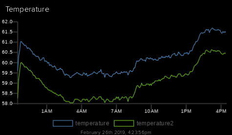
It uses a pair of temperature sensors and records it to an MQTT server. It revealed that my garage seldom gets below 55 degrees or so (not too surprising, since the weather here seldom gets that cold, but we did have a couple of snaps down around freezing). Over the last 24 hours it’s recorded the following:

From my garage…

This data comes from a Microchip MCP9808 board, and the temperature reported by an MPL3115A2 barometric pressure sensor. I haven’t bothered doing a calibration to see which one is more accurate, but you can see that they seem to report the same values up to an offset. Both are more accurate than I really need.

Several years ago I didn’t have such sensors in my junk box, and tried just measuring the forward voltage drop across a very cheap 1N4148 diode. That “worked” after a fashion. It wasn’t especially sensitive, since each bit of the value returned by analogRead() turned out to be about 2 degrees C. The post generated some comments however, and pointed out that I could use either the internal 1.1V reference or the actual internal temperature sensor to get more accurate values. It was fun, but soon after I got real temperature sensors which promised still better accuracy, and I didn’t revisit the issue.

But today I found an interesting and different approach on the Cave Perl Project Blog. The ATmega328p used on the Arduino uses an internal RC oscillator to run the watch dog timer. It runs at around 110Khz, but isn’t especially accurate. It is… you guessed it… highly temperature dependent.  So, you can time the amount of time it takes the WDT to overflow, and with some math determine what the temperature might be. And it turns out that the results are likely sufficiently more accurate, perhaps down to around 0.1 degrees C, which is better than a lot of inexpensive sensors. There are some details which are interesting to read and think about, but I might have to try experimenting with this.

In any case, the website is actually pretty cool for other projects as well. It was founded to develop “a submersible data logger system for long term environmental monitoring projects” and has lots of other good data and ideas. I’ll probably be killing a few hours reading it tonight. I think you all could do worse than do the same. 🙂

Have a good one.

My Computer Controlled Etch a Sketch…

I’ve been wanting to make a computer-controlled mechanical gadget for quite some time. When I finally got a 3D printer a little more than a year ago, I began to think of how I might make a device that could direct a pen under computer control. I even took the time to order a CNC shield which could be used to drive the four channels needed for a 3D printer, but I never really got too far on that project. The NEMA-17 steppers that I ordered have largely sat in a box.

Until a couple of days ago. I wanted to do something, but maybe wasn’t quite ready to embark upon a project as complex as a 3D printer or CNC milling machine conversion. If the cost was low enough, it wouldn’t matter if the thing I built was particularly great: I would learn enough by doing the project to make it worthwhile, and I would gain confidence that perhaps would make me enthused enough to try a bigger project.

Hence, the computer-controlled Etch A Sketch project was born.

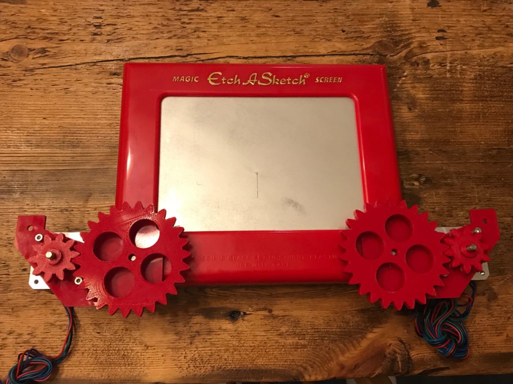
I’m of course far from the first to do such a thing. I didn’t let that particularly bother me. I sometimes refer to my hobbies as “timidly going where others have gone before,” and this is no exception. I knew that I wanted to use two of the steppers I had on hand, and probably use the CNC shield that I had. A quick order to Amazon Prime had a nice shiny new Etch A Sketch delivered to my house, and I went to Thingiverse to see what kinds of brackets and adapters people had used on their project. I settled on this set of parts and set my newly repaired and functional Creality CR-10 to printing the new parts.

There were a couple of issues. The original page didn’t have STL files for all the parts, you had to refer to older projects to get the STL files for the larger gears. When I printed one, I found that the center hole was significantly loose. Luckily, the author had uploaded the OpenSCAD file for generating the gear. Reading through the code, I found that the shaft hole was set to a diameter of 5.25mm, whereas a quick check with calipers revealed that mine were more like 4.5mm. I went ahead and printed a new one and tested it. It was a very tight press fit, which was just what I wanted. Huzzah!

The two mounting brackets are curved to fit the front panel and are to be attached with hot glue. I was dubious about this, but a reasonably large amount of glue was spread and the brackets pushed into place. It seems to work rather well, and it looks like they will hold just fine. I then pushed the two gears onto each side. There was a little bit of vertical misalignment: the large gear on one side was originally pushed quite deep, and didn’t mesh well with the smaller gear when it was in place. I used a flat bladed screwdriver to pull it back away from the body until it lines up pretty well. As yet, I don’t have any code to drive the motors, but turning the shaft by hand seems reasonably easy and the amount of backlash or slop is, well, probably not a big deal.

My intention was to drive the two steppers with a system like GRBL, which is a G-code interpreter that is used to drive CNC machines using an Arduino and some stepper drivers (provided by the CNC shield that I mentioned above). But as of this moment, I seem to be having some difficulty configuring the software. I may actually instead just write some simple code to test the stepper motors (perhaps by driving the steppers to draw a square on the Etch-A-Sketch) before I try to anything more complicated. It really wouldn’t be hard to drive the steppers using a simple set of drawing commands: all I’d need to do is dust of the Bresenham’s algorithm that I learned back in my early teens, and I’d be good to go. Next step is to read up on the wiring for the CNC shield wiring, and get the 12V supply running to the steppers to power the gadget. It might also be good to 3D print a stand to hold the Etch A Sketch in a more upright position. Hopefully, by the next time I post about this, I’ll have some video of it doing something nice.

Stay tuned.