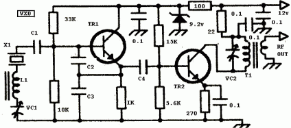
A Universal VXO by George Dobbs G3RJV
Well, you can’t do better than an article by the legendary George Dobbs, G3RJV. The circuit that he has closely resembles the oscillator that I just built, with a few distinctions.
A Universal VXO by George Dobbs G3RJV
The general topology is the same, but the resistive voltage divider that feeds the base of the transistor has resistors of 33K and 10K in George’s design, while they are a simple 10K/10K in the EMRFD design. In other words, EMRFD biases the transistor with half the supply voltage, while George’s design is more like divide by four. George’s design says that the capacitive divider should have 100pf capacitors, EMRFD specifies the very high 390pf. The resistor that grounds the emitter is a 2.2k ohm resistor in EMRFD: George specifies a 1K ohm.
Addendum: My oscillator sounded a bit chirpy, and with some additional harmonics, so I began to look up designs for harmonic output filters. Of course, Dobbs has another excellent resource containing worked out designs for all ham bands.
Addendum2: Here’s a link to the GQRP clubs technical info page, which is a superset of the information provided in the link above.

I recall burning three or four weeks of a sabbatical getting Saccade.com on the air with Wordpress. So much tweaking…