I recall burning three or four weeks of a sabbatical getting Saccade.com on the air with Wordpress. So much tweaking…
On light in drops of water…
A couple of days ago, I linked to an article which talked about using a laser beam as a kind of microscopic projector. The collimated laser light passes into a small drop of water, and then casts the image of protozoa (or other small swimmers) onto the wall. Very cool, but I wasn’t entirely sure what was going on here. The actual physics of the image formation is remarkably complicated, so I thought I’d try to understand it more or less from first principles.
Warning: I could be totally wrong about this stuff. While I have all the right books to figure this stuff out, I haven’t dug them up or consulted them beyond some minor exploration of a couple of formulas.
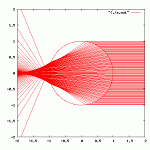
I began by ignoring the wave theory of light entirely (which won’t get us very far, but it’s where I’m starting). What does the distribution of light look like when it is refracted through a spherical drop of water? I looked up the index of refraction for water (around 1.33) and wrote a simple 2D raytracer which uses Snell’s law to trace rays through a sphere. Here’s the result:
A couple of things to notice: the beam doesn’t converge inside the water droplet: it is “focussed” in a region outside the sphere. It isn’t focused to a single point, it exhibits classic “spherical aberration”: the rays which hit the drop at different vertical positions cross the horizontal axis at different locations. This raytrace also implements what is known as “total internal reflection”: when a ray passes from a dense (say water) medium into a less dense medium, there is a critical angle where instead of refracting, the ray is reflected. It is a rather interesting quirk that this situation doesn’t occur in this hypothetical situation: all the rays hit the far side of the sphere at angles below the critical angle, and therefore exit the sphere after just two air/glass interactions.
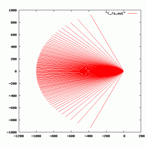
If we zoom far back, we can see what the distributions of light should be:
The light is scattered in a smooth lobe out the far side of the laser. In Alan’s photos, you can see a very bright spot, which I suspect is caused largely by the fact that the droplets he was examining where very much smaller than the beamwidth of his laser, and you are simply seeing spillage around the laser light.
I was originally confused because I was thinking there simply had to be rays in this simple setup which would exhibit total internal reflection. My thinking was that rainbows appear opposite the sun in the sky, so there has to be a reflection to get light back into your eye. But the mechanism of this propagation isn’t by total internal reflection, it is governed by the Fresnel equations. Whenever light passes between two media which have differing refractive indices, both reflection and refraction may occur. The critical angle of Snell’s law is simply a subset of the behavior described by the Fresnel equations. Fresnel’s equations predict the reflectance and transmission at interfaces based upon the angles and media. Using this, you can determine that even at angles which are normal to the surface, you get some reflectance (in the case of air/water, about 2% of the light is bounced back). It is this Fresnel reflectance on the interior bounces which is apparently responsible for the appearance of rainbows.
(Of course, rainbows rely on the fact that the refractive index of a material is wavelength dependent. Our laser is essentially a single wavelength, so we won’t ponder it further now).
Anyway, back to the laser projector. It was apparent to me from the original video that there were significant diffraction patterns around each Protozoa, and Alan’s video (with much smaller critters) is primarilly full of diffraction patterns. It is my believe that most of the light passing through these drops is actually propagating via diffraction (much like Gabor’s inline holograms) rather than simple projection. The laser beam doesn’t form a small point inside the droplet, it is much closer to being a single collimated beam. This means that potentially the methods used for digital inline holography could be applied to this very simple experimental setup.
More thoughts on this as they occur.
Comments
Comment from Anders
Time 8/24/2012 at 11:05 am
I found your article because I just read this article showing a “spherical glass solar energy generator”. (http://www.designboom.com/weblog/cat/16/view/23214/spherical-glass-solar-energy-generator-by-rawlemon.html)
When looking at conventional solar power devices they are mainly flat or parabolic. I assume this is because of the need to get as much surface area exposed to direct sunlight as possible.
A sphere would have a much higher surface area but would not get as much direct sunlight compared to the flat and parabolic shapes.
Do you think the access to indirect sunlight could make up for the lower areal of direct sunlight?
Sorry if this was too off topic.
Comment from Anders
Time 8/24/2012 at 11:10 am
Im assuming that the surface area of direct sunlight is less for the sphere because the light is not as directional from the sun, unlike your laser. I might be wrong about that.
Comment from Mark
Time 8/24/2012 at 3:35 pm
Using a sphere for this seemed kind of odd. It’s probably true that a sphere presents less wind loading compared to a flat plate of similar total area, but that was the only dimension along which I think such this makes sense. To make this concrete, let’s compare an ordinary photo-voltaic system with 1 square meter of area with a sphere which has a surface area of 2 square meters (only 1 sq of the sphere faces the sun at any given time). The sphere would have an radius of sqrt(2/(4 pi)) = .39 meter, or a diameter of .78 of a meter. The volume of such a sphere is almost 2 cubic meters. Water weighs 1g/cm^3, so 1m^3 weighs 1000000 grams, or 1000kg. The sphere would weight 2000kg, and if were made from glass (which has a typical density of around 2.5g/cm^3, you’d be talking over 5000kg. (Hope I got my sums right.) You might be able to use some lighter plastics, but you are still talking several tons, for even the most modest solar collector. Even if the weight were not a factor, the cost and manufacturability absolutely is. Glass is not particularly cheap, particularly in these kind of large sizes, and they are hard to manufacture.
And even then, you won’t get the full efficiency that you get from having a flat plate tracker. The flat plate has the virtue that the normal to the surface points at the sun, whereas the normal to the sphere does not. The Fresnel effect thus limits the amount of energy that actually enters the sphere, reducing the overall efficiency. My simulation in this post didn’t show this effect, but later simulations I did do, and the amount of energy scattered upon entry is not insignificant.
It just seems like a questionable idea on every front to me.


Comment from Myles VK6ZRY
Time 2/5/2012 at 12:45 am
I had a similar experience using a laser to illuminate a reflective surface, the relections were spread out on a wall. The surface was magnified as an image on the wall, the contours of the surface appeared in great detail.
I can imagine the contents of the water drop being displayed in a similar fashion.