I recall burning three or four weeks of a sabbatical getting Saccade.com on the air with Wordpress. So much tweaking…
A $.33 MAX232CPE, or a $0.01 2N3904?
In response to my previous post, @xek replied:
https://twitter.com/#!/xek/status/163442298456260608
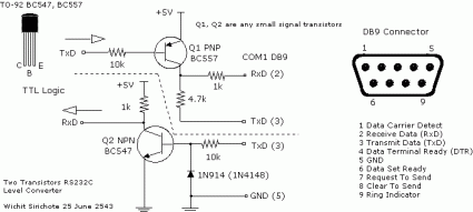
Well, the fact is I had heard of doing that. It’s not really hard to rig something that will convert the RS232 level from the GPS into TTL levels for the Arduino. It just takes a single transistor inverter: you rig an 10K resistor from the RS232 signal to the base, a 1K resistor from 5v to the collector, and then ground the emitter. Tap the transistor on the emitter side, and voila! It works. I rigged this up on the breadboard and checked it on the scope, and sure enough: 5v and 0v. I then coded up a simple sketch which used the SoftwareSerial library: it instantiates a serial port, then copies bytes when available to the normal Serial output device. Once I remembered that my GPS output at 4800 baud, the program worked flawlessly.
 After I got this working, I gave the other direction a tiny amount of thought. I couldn’t think of a good, simple way to convert the TTL level to the negative levels without using some kind of charge pump, or a negative supply. But there is a cute trick you can use, that I discovered while surfing for alternative circuits: check it out. The trick is that if you are operating half duplex (only one side of the transmission transmits at the same time), the transmit line will go to the negative state. So, if you need to output a negative value, you simply swipe the voltage from Tx side of the RS232 line. That just takes a PNP transistor. Very cute.
Addendum: the receive circuit looks the same as mine, except they add a diode. Novice that I am, I don’t get why it is necessary or desirable. My circuit seems to work fine without it: can someone with experience tell me why it’s a good idea?
Addendum2: The MAX232s aren’t wasted: I am using it as an opportunity to learn Eagle and design a simple but still useful PCB. I’ll still be working on that.
Comments
Comment from Lionel Cordesses
Time 1/29/2012 at 3:51 am
Dear Sir,
First, happy New Year !
I’ve just read your post about the TTL to RS232 levels with a transistor. I used a similar trick published in Elektor magazine in November 1987 (issue number 113).
You can find a scan of the schematics at:
http://vesta.homelinux.free.fr/site/wiki/fichier_8052ah_5.html
You will see that there is a capacitor C1 that takes the negative voltage from the Rx line.
I have used it for years and it works well (as long as you do not connect two units using the same trick: one must be a real provider of negative voltage).
Regards,
Lionel
P.-S. I will answer as soon as I can most of your questions regarding the SSTV article my Dad and I wrote in QEX (the choice of the sampling frequency for instance).
Comment from Mark VandeWettering
Time 1/29/2012 at 10:09 am
Thanks Kenneth, that makes perfect sense. My newbie status is showing.
Comment from Mike K
Time 1/30/2012 at 4:13 pm
I use two FETs, like this:
http://i176.photobucket.com/albums/w174/upand_at_them/2n7000_dual.jpg
(Not my design.)
Comment from Kenneth Finnegan
Time 1/28/2012 at 11:07 pm
The diode is to clamp the base above -0.6V, because transistors really don’t like negative base voltage. Like, REALLY don’t like negative voltages. For example, the 2N2222 is only rated for 5V emitter-base voltage, so even just the -6V of RS-232 stands the chance of breaking down the bottom PN junction.