I recall burning three or four weeks of a sabbatical getting Saccade.com on the air with Wordpress. So much tweaking…
Accuracy of the DS1307
My tinkering with using the Adafruit GPS as a time base has yielded some results. I’m still getting a few spurious interrupts when I feed my buffered PPS signal into the interrupt pin on the Arduino, but they are relatively few and far between (and quite regular in appearance).
A few short notes, followed by my conclusions.
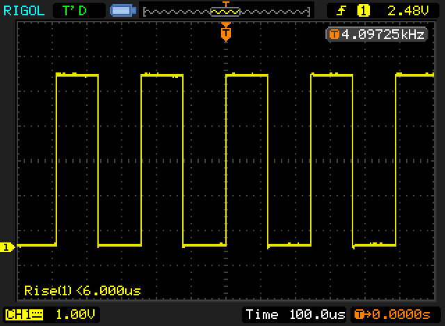
The PPS signal from the GPS is a pulse at 1Hz, which remains high for 100ms and then drops back to the ground state. The voltage peaks out at 2.8 volts.
The SQ signal from the Tiny RTC board is a (nominal) 32768 Hz signal. it’s a 5v square wave, with a 50% duty cycle.
(This screen capture is actually for a 4096 Hz signal which I experimented with earlier, but have since changed to a 32768 Hz signal).
I wrote this code to use the 1PPS as a signal to count the number of clock pulses per second.
[sourcecode lang=”cpp”]
//
volatile uint32_t clk_cnt = 0UL ;
volatile uint32_t pps_cnt = 0UL ;
volatile bool dirty = false ;
void
pps_interrupt()
{
pps_cnt ++ ;
dirty = true ;
}
void
clk_interrupt()
{
clk_cnt ++ ;
}
void
setup()
{
Serial.begin(9600) ;
Serial.println("CLOCK");
pinMode(2, INPUT_PULLUP);
pinMode(3, INPUT_PULLUP);
attachInterrupt(0, pps_interrupt, FALLING);
attachInterrupt(1, clk_interrupt, RISING);
}
void
loop()
{
for (;;) {
if (dirty) {
dirty = false;
Serial.print(pps_cnt);
Serial.print(" ");
Serial.println(clk_cnt);
}
}
}
[/sourcecode]
I encountered a couple of odd problems though.
Initially, I seemed to be getting spurious calls to the pps_interrupt. In particular, while the PPS signal was high, transitions of the CLK signal seemed to trigger spurious calls to pps_interrupt. Thus, I’d get about 3270 additional calls to pps_interrupt.
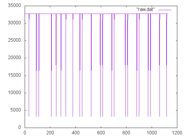
I was suspicious that perhaps the 2.8v PPS signal was causing some problems somehow. I constructed a simple inverter (1K ohm resistor into the base of a 2N3904, with a 10K resistor connecting the collector to the 5v supply, output tapped below the resistor). When I hooked up the output of the inverter to the Arduino interrupt input, I got much better results, although there still seemed to be an odd transition or two when the PPS swapped state. You can see the result in this graph:
The low end of measurements are all approximately (nearly exactly) 10% of the average value. In looking at the raw data, you can see these low values are followed by a value which is 90% of the average value: in other words, they sum to the average value, which indicates that the interrupts were spurious, and likely happened when the pps signal returned to the HIGH level (remember, we now have a buffer inverter in place).
If we ignore the spurious interrupts, we can calculate the accuracy of the DS1307.
Using this data, we find that the clock is running a bit fast: there are 32777.652 transitions per second, instead of the nominal 32768. If you multiply this out, you get that the DS1307 runs about 25.44 seconds fast per day. That’s pretty miserable, about 300ppm. I’ll double check the math again, but so far, I’m suspecting that perhaps paying more than $3 per module would be fruitful if accurate time keeping is required.


Comment from Chris Johnson
Time 5/21/2015 at 4:40 am
If you are constructing this on a breadboard, maybe insufficient decoupling or excessive ground plane inductance are causing the problems. Using Schmitt trigger inputs on the microcontroller might help.
In the software, what happens if one interrupt is triggered while the other is executing?