A few years ago, I got seriously interested in amateur radio and satellites. I would often haul out a small Yagi antenna and my trusty Kenwood TH-D7A and try to talk to other hams by bouncing signals off the various satellites which acted as amateur radio repeaters. During that time, I wrote a Python version of G3RUH’s Plan-13 algorithm for predicting satellite locations. Eventually, I converted that code to C++ and made an Arduino/Gameduino version that I called “Angst”.
But there were a number of problems with it as a general project. Most notably, it utilized some special hardware which made it more expensive than I would like, and it required an external display. I suppose I could have found a small composite display, but one serious issue remained: there was no simple way to update the orbital elements that are used to predict the satellite locations. The ISS is particularly problematic, since it is in low earth orbit and frequently fires its engines to boost it to a higher orbit, which is not something that can be accounted for statically.
But in the years since I did that project, the ESP8266 has taken the world by storm. Not only is it cheap (I got some WeMos D1 Mini clones for less than $5 shipped from China) but it is faster (an 80Mhz 32 bit processor) and most importantly includes WiFi.
For the last couple of days, I’ve been tinkering my old Plan-13 code together with some new code written especially for the ESP8266 to create a “clock” that will automatically tell me the position of the ISS and details about the next pass. The nice thing is that since the ESP8266 has WiFi, it can update itself automatically. Right now, I have code running that contacts celestrak.com, finds the latest orbital elements, predicts the next three passes, and then enters a loop where it shows the current position of the ISS every five seconds. Right now, it just echoes that information out on the serial line, but eventually I’ll get a tiny TFT or LED display to display the live information:
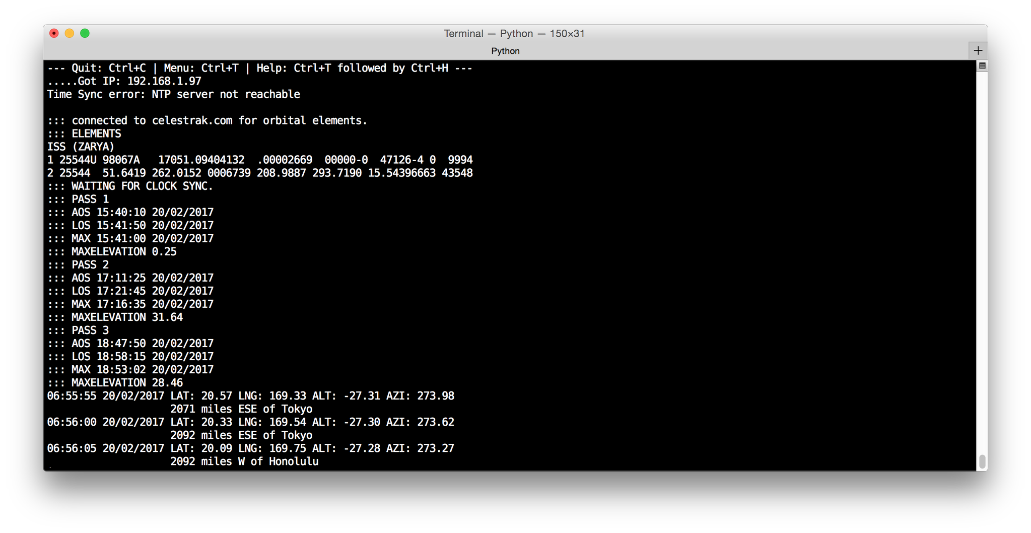
But just seeing the latitude and longitude of the “sub satellite” point didn’t really help me know where the satellite was in its orbit. Sure, I could (and probably will) make a little graphical display for the gadget sooner or later, but I thought it might be nice if I could have it tell me when it was passing close to certain major cities. To give this a try, I found a list of world cities and their coordinates and population, and selected the top fifty cities of the world and within the United States (make one hundred cities total) and then when I do a prediction, quickly compute the distance and bearing to each of the cities and display the closest one. And that works, and doesn’t take too much time. You can see in the run above that the closest city was Honolulu.
But, I noticed a problem.
If you imagine that the earth is a sphere, and imagine that the each city is a point on the surface which you can think of as a seed. If you collect all points on the sphere that are closest (in the great circle) sense to that point than any other seed, you end up with the globe being divided up into a number of regions, each bounded by arcs of a great circle. If you took the same computer and math classes as me, you can recognize this as a “spherical voronoi diagram”. You can read about them here where I swiped the illustration from. Here is the Voronoi diagram of the earth with seeds at each of the World Airports:
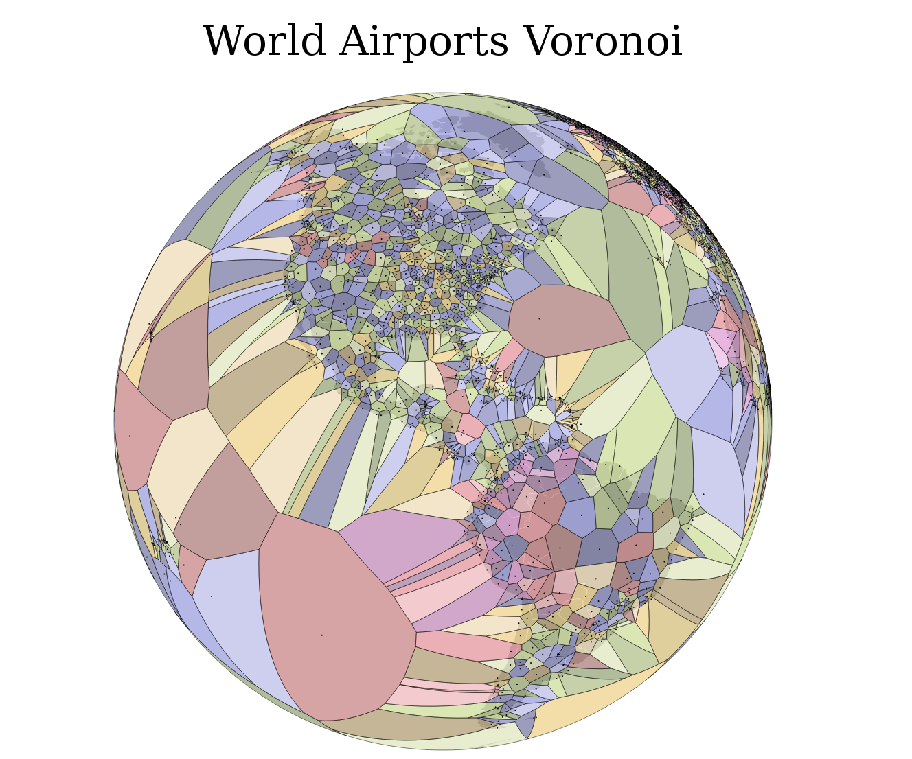
You’ll notice something: the regions are widely varying in size. If I had loaded my ISS code with these locations, it would spend a lot of time talking about how it is thousands of miles from some remote airport in the middle of the Pacific, but when it was flying over the United States, it would rapidly shift from region to region. Indeed, because population centers are often close, it might be fairly rare for it to be closest to New York City, even though it is perhaps an obvious landmark, more obvious than the smaller ones that surround it. It might also be the case that if you have two population centers which are fairly close to one another, that approaching from one side would be masked by the other city.
Ideally, we’d like a collection of cities which:
- are well known
- divide the globe into a number of Voronoi regions which are nearly the same size
- and where shape of the Voronoi regions are not too lopsided, so the cities are near the center of a roughly circular region
I haven’t figured out how to do this yet, but I’m betting that I am going to use some kind of genetic algorithm/simulated annealing approach. Stay tuned.