Yes, it’s me, back after a far too long hiatus. Sometimes life intervenes, and you just have to reset your priorities. But rest assured, the geeky stuff that I used to work on and chronicle in my blog continues, and on this long Labor Day weekend, I thought I might mention a project I’ve been working on.
Long time readers of my blog may remember that I experimented with using a Raspberry Pi and a Raspberry Pi Camera module to get pictures of my hummingbird feader. Here is a refresher in case you don’t remember or didn’t see it. But at the time it was just a prototype. In particular, I never constructed a permanent setup for it. It got put back into a box, and I didn’t think about for a while. Over the last year I had major construction in my back yard, replacing a retaining wall, and our feeders were down for a long time. But that ended, and I recently started to get a tiny amount of free time. So, I thought that it would be fun to try to make a more permanent version of this project.
But I decided to do a bit more. I decided that what I wanted to do was to create a small solar powered “pod” which could be used to hold the Pi, and which could be reconfigured for other uses.
So, I bought a few goodies to help me along the way:
- Allpowers 20A Solar Charge Controller I didn’t have to go with a charge controller for this project, but I thought that I might as go with one a bit beefier than I needed for this project.
- ML7-12 7.2aH SLA battery I just wanted an inexpensive SLA battery to go with my charge controller.
- A Newpowa 10W 12V solar panel I wanted something a tiny bit bigger than the small 6V panels that you commonly see, and again, this one was modestly priced.
As it happens, this system is probably not really enough to run an Raspberry Pi with a camera for 24/7, even with pretty good sunshine during the day. But I wasn’t sure how far off it would be, and how efficient the charge controller would be.
If you’ve never set up such a system before (I hadn’t) the basic idea is the charge controller has three sets of terminals:
- the solar panel
- the battery
- the load, which is regulated 12v output to drive whatever it is you are powering
The basic idea of the charge controller is to make sure that the voltage and current from the solar cell are efficiently applied to the battery to charge it. The charge controller that I bought is also supposed to prevent over discharge by disconnecting the load from the battery if the voltage drops too low, and which also is supposed to prevent overcharging.
So, I thought I would test it out.
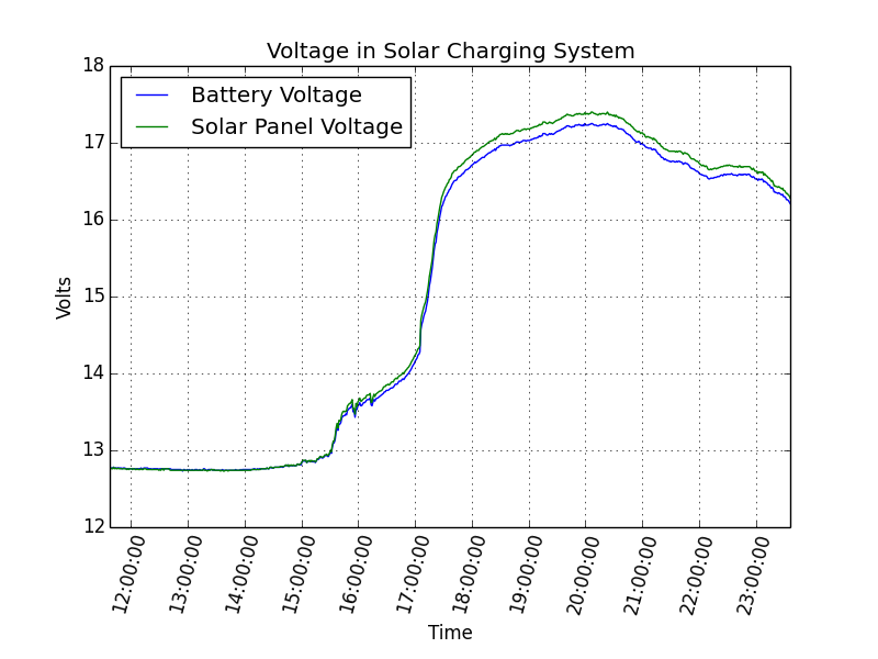
Instead of using my Raspberry Pi, I dusted of a WEMOS D1 Mini, my preferred < $5 ESP8266 module. To it, I connected a pair of INA219 modules, one that would read the battery and voltage directly from solar cell, and the other that would do the same for the circuit that leads to the battery. The ESP8266 would take all these measurements once a minute, and would upload them to the Adafruit MQTT server. You could view them directly from their dashboard, but I downloaded 24 hours of data, and made some graphs using matplotlib. The sensor data from the solar panel are in blue, whereas the data from the battery is in green.
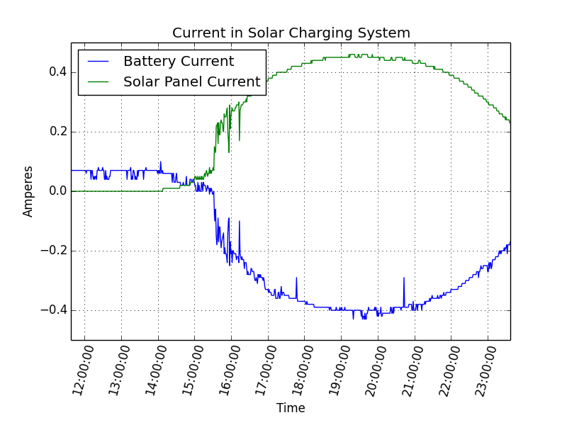
Some of the data makes sense to me. Looking at the current data, you can see that the graph starts with no current from the solar panel, as it is starting in the dark. We see that there is a current running out of the battery (it’s discharging) at a rate of somewhere around 70mA. But as the sun rises, we begin to get current from the solar cell. It’s current climbs, and the current into the battery falls, eventually reversing as it begins charging the battery. That all seems great.
But here is what confuses me. If we look at the voltage, sunrise occurs around 15:00 UTC and the voltage begins to climb. It goes up, and up, and up. I believe that I had the “overcharge” setting to be around 13.7v. I would expect that as the solar panel becomes more brightly illuminated, it would pass that level, and I would expect the charge controller to reduce the amount of current to the battery. But we really don’t see that. The current stays quite high, eventually topping 0.5A at 17V, or about 8.5w. This doesn’t seem good to me. The voltage on the battery terminals gets quite high (topping 17v) and I’m worried that it might be overcharging. I’ve double checked my hookup, the settings on the controller, and I’m baffled.
Can anyone provide any insight as to where my understanding might be going astray?
I’ll eventually write up a complete description of this project, so if any of this doesn’t make sense and you have any questions, feel free to leave comments and questions, and I’ll try to explain further. Eventually the code and other bits of information will show up here.
Thanks everyone….