This weekend I mostly did work on further organization and cleaning of my garage workshop. This included taking out the old dog door and cutting a plywood cover to block it up, putting up a monitor mount so I could hang a new $80 22″ HDTV that I could use as a monitor, and then some general cleaning and organization of four shelving units.
But as I finished, I thought I would go back and try to understand the issue with my solar project. When I had taken it in from the outdoor location, it seemed to go off line, and no longer connected to the Adafruit IO service that I have been using. I suspected that I knew what the issue was, but today was first time that I could sit down and actually debug it.
The problem arises because of the haphazard way I cobbled together the code that runs on the ESP8266 module. It begins (in its Arduino setup() function) by probing for the existence of all of the I2C sensor modules that are installed. When I first coded this up, I wanted it to check just so I could be sure that the peripherals where installed and accessible via the bus. Thus, if it didn’t detect the peripheral, it printed a warning message and then entered a dead loop, where the watchdog timer would force a reset.
Of course, when the module is deployed in the garden, this isn’t especially useful. As I coded it, the check occurs even before the WiFi network is initialized, so no message gets sent. This also prevents the system from being able to be reflashed with an OTA update. Not a good state of affairs.
This was the state when I sat down at the workbench today. I could have simply hooked the ESP8266 module up via the USB to my laptop and worked on debugging it that way, but I had a new technique available, so I decided to use it. I had a second module programmed with the esp-link software (as I described in a previous posting) so I was able to monitor the boot messages.
What I discovered was that the MCP9808 temperature module was not being found by the I2C bus probe. To help with debugging, I decided to write some code that would try to probe all available I2C addresses, and print out a nice table of all the peripherals it found.
What it revealed was that the MCP9808 was actually being detected at address 0x19, whereas the default location was 0x18. The module does have three address pins to allow you to change its address, but according to the schematic, it has resistors in place that should pull the address low.
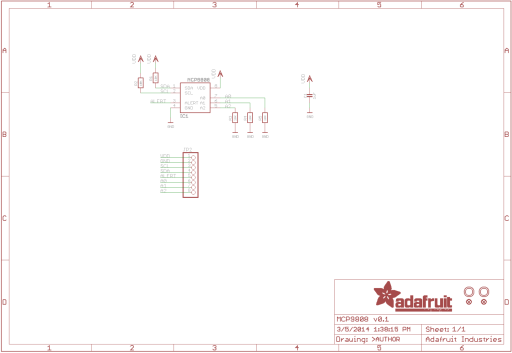
I’m was confused why it was acting as if A0 is pulled high, but I decided to just install a jumper to tie it to ground. And, boom! Booted right up and started to log data again for the first time in a week.
So, it’s working (after a fashion) but it does spawn a bunch of new tasks for me to work on for the next few days.
- First, why did I need to tie the address pins explicitly low? Never seemed to have to do that before. It puzzles me, and I’d like to resolve it.
- Rewrite the application. In fact, I’ve already begun on this. The biggest change is that it’s much more forgiving about the absence of peripherals that it expects to find. Notably, it connects to the WiFi network first, and only then does it start to probe the I2C network and take telemetry measurements. It’s also careful to ensure to process messages related to the Over The Air (OTA) updates, so that if I do need to update the software, it will be listening for the updates.
- And while we are at it, I think it’s time to stop using Adafruit IO’s MQTT server. It’s a good, quick and easy way to get started, and allows you to setup a quick dashboard, but there are a number of problems that make it less than ideal. In particular, it doesn’t support retained messages properly, either in the client side or on the server. I have installed the mosquitto server, and will eventually move to that instead. I have decided to shift to the PubSubClient library which also appears to work with SSL and provides the retained message support that I like.
- The current version is rather overactive: it records telemetry once a minute and pushes it to the servers. In between, it’s running, just busywait-ing in a loop, on the off chance that it receives a request to update its firmware. The new version should update telemetry at a longer interval, and use deepsleep to lower its power requirements in between.
- The current version of the software is one-directional: it just sends telemetry to the broker. But MQTT is a bidirectional protocol, and it can receive information from the broker as well. I’ve tested this a bit, and envision it be able to send new configuration messages to the sensor.
- In particular, we can use retained messages to set the “mode” of the sensor. When the sensor wakes up, it will receive a retained message from the broker indicating what mode it should be in. If it is in battery saving mode, it does a read of all its sensors, sends them to the broker and then goes to deep sleep to save energy. If the mode was “wait for update”, then it can enter a loop where it stays alive, waiting for a firmware update.
That’s about it for now. Stay tuned for more (and eventually code on github).
This is all good stuff to know for my planned bird feeder project. 🙂 Thanks!