Okay, here’s a strange little project that is pushing the limits of what I understand in a couple of ways, and I thought I might write it up and also ask a question from those more knowledgeable than me.
Here’s the idea: in our upstairs bathroom, we have a Litter Robot. This is a commercial product, and basically is a spherical pod that serves as a litter box. When the cat does his business, motion detectors note his arrival and departure, and several minutes later motors engage which rotate the pod around and cause the waste to be sifted and removed from the box, and then rotates back to its starting position. Our cats seem to like it just fine, and it means that daily scooping isn’t required. Huzzah!
As it happens, there is an add-on to this model which makes it an IoT device and it will communicate its operation and control via BlueTooth to your phone. I thought this was a kind of frivolous (and not inexpensive) addition, so we didn’t bother. But refusing to spend a lot of money on a well designed product means I can spend a similar amount of money to bodge something of my own that will be a finicky Rube Goldberg. I justify this by noting that it is a learning opportunity.
I should also thank Brian who inspired this project with a similar “cat litter box” theme: he wants to automatically trigger an exhaust fan. I’m more interested in just the “sensing” part, and may use something like dweet.io or possibly MQTT to merely log when the Litter Robot does a cycle.
Rather than try to do any reverse engineering of this (rather expensive) robot that my wife really loves, the approach that I thought would be most reasonable (and which Brian is again responsible) is to create a current sensor that will note when the current to the robot increases, indicating that the motors are engaged. The way that we decided to do that is by using a current transformer. The idea is to basically create a short extension cord that passes the hot wire from the AC circuit through the center of a clamp on current transformer. You can plug this into the wall, and plug the desired appliance into the other side, and the current transformer will supply a signal (either current or voltage depending on what type you get) that can be sampled by a microcontroller, and you can then do appropriate action depending on what you discover.
So, a scrap piece of Romex, and a trip to Home Depot later, along with an order for a current transformer, and I created this little experiment (again, following in Brian’s footsteps):
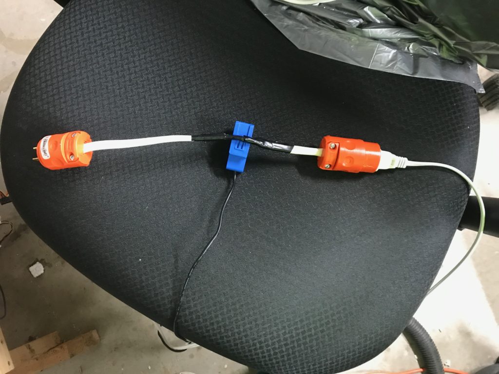
The extension cord is just indoor Romex, which consists of three 12 gauge wires in a plastic cover. The ground wire is basically a bare copper wire, and it has two insulated wires which are white and black. You wire the bare wire to the green plug, and then put the white on the silver screws in each end, and the black on the gold colored end. I then checked the operation, first with a wiring fault detector, and then by just trying to use it as an extension cord. No problems were noted, so it was safe to proceed.
I then slit part of the out covering to expose the inner wires. The current transformer is (I’m told) only supposed to have the “hot” or black wire passing through it, so I created a little slack and passed it through the snap on part of the current transformer. A little electrical tape (and a little more for good measure) and I was done.
The current transformer is an SCT013-010 from YHDC which cost about $15 via Amazon with Prime. Here, I will tell you pretty much all I know about such things, since I am well out of my areas of knowledge and experience (which is rather the point of this project).
A current transformer is used to monitor the current flow in a circuit. When the current flows through the hot wire which passes through the center of the ferrite core, it induces a much smaller current on the output of the secondary.
If the current transformer is of the “current output” type, then a shunt resistor (called the burden resistor) is normally placed across the output, and the voltage drop is measured across it. Since you know the voltage drop and the resistance, you can solve for the current through the secondary, and then use the specification of the transformer to compute the current through the primary circuit. Normally the output of such a transformer has a pair of protection diodes wired across the outputs because if the secondary output is an open circuit, the switching of the AC causes large voltage spikes at the output, which isn’t good.
If the current transformer is of the “voltage output” type, then the burden resistor is built in to the transformer, and the output is merely a voltage. There doesn’t appear to be a pair of protection diodes that were present in the current monitoring type, likely because the resistor is built in.
The type that I chose was a voltage output type, with a nominal rating of 10A/1V. I took this to mean that if a 10A AC current was flowing through the primary, it would generate a 1V output on the output of the circuit. This means that the signal would be about 100mV/A, which I thought would be about right, or at least measurable via the ADC in an Arduino or an ESP8266.
But before I tinkered with putting a microcontroller in, I thought I should just look at the output of the sensor. I plugged a lamp into my extension cord and I hooked up my trusty Rigol scope to the output of the current sensor and had a peek. And here’s where something confusing happened: I got this.
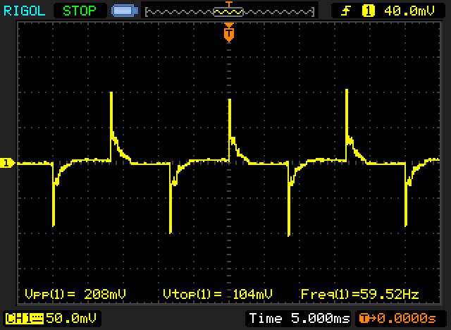
See, I was expecting to see something approximating a nice sine wave. Unless the transformer is operating in “saturation” mode, one would expect the output to be more or less a linear representation of the input current. But that’s not what we have here. It looks rather like the kind of spikes that you’d expect from some kind of kick back from switching an inductor, but that’s well, not supposed to happen, at least as far as I know. This kind of signal is pretty useless for trying to determine power consumption, since it’s not at all linearly related to the input power.
Five minutes after getting this result, I realized that I was tired and it required more pondering. I shut it down and went to bed. This morning, I still find it to be pretty odd. I’m wondering if perhaps the bad waveform has something to do with the nature of the load I placed on it: the lamp was a cheap compact fluorescent that also serves as a bug zapper. Could that be part of it?
In any case, I am in unfamiliar waters, and if anyone has any suggestions, feel free to tweet (@brainwagon) or leave a comment here. I’ll update you with more information as the project continues.
Addendum: I just went out to the garage and tried a different load. I had a parabolic heater from Costco sitting there, so I decided to plug it into the circuit and see what it did. It generated a much more reasonable looking waveform.

This signal was about .82V rms, which represents a current of about 8.2A, or a total power (assuming 120V) of about 984 watts (the nominal rating of the heater is 1000W). Huzzah!
So, the new questions are:
- Is the problem with the other load merely that the load is too low to be measured accurately, or is it the nature of (maybe) a poorly switching fluorescent?
- Does the Litter Robot have sufficient current draw to operate in this more linear regime?
Stay tuned for more information.