A couple of days ago, I found out about thecavepearlproject.org through a link on hackaday, and an article which gave an interesting idea about how to do temperature sensing using an Arduino and no additional parts. I didn’t really recap the actual underlying technique. The idea was a fairly interesting one. The watch dog timer (WDT) in the ATmega328 (the chip of many Arduino variants) is normally used to help detect if your embedded application has crashed or hung. You configure the watchdog timer to trigger a routine (ISR, or Interrupt Service Routine) after a given interval, say one second. In your application’s main loop, every once in a while you “feed” the timer by calling the wdt_reset function. This resets the timer, and keeps the ISR from triggering. If your application goes into a loop or hangs, then the wdt_reset won’t get called, and when the timer expires, it triggers the routine (perhaps resetting system).
What does this have to do with temperature sensing? The WDT is driven by an oscillator inside the ATmega328, and which runs independently of the main (usually crystal) oscillator. And, as it happens, it is not engineered to be especially accurate or stable. It is not derived from the input crystal (crystal oscillators are normally pretty stable). In particular, it is not designed to be temperature stable. And it’s not. It’s that instability that makes using it for temperature sensing. You measure the time it takes to trigger the WDT, and then, with a little math (more below) you can figure out the temperature.
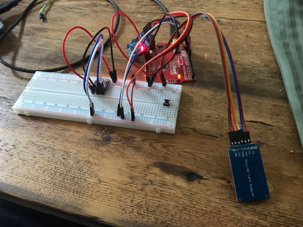
Anyway, that’s the theory. I wanted to give it a whirl. So, I tinkered together some code, using my favorite development environment platformio, and running on a Sparkfun RedBoard, with some other sensors that I had lying around: an Si7021 temperature humidity sensor and a DS3231 real time clock. Previous data logging experiments I had done mostly used to log data to the Internet (I mostly have been using ESP8266 boards like the WeMOS D1 Mini), but I was inspired by the work on The Cave Pearl Project website, so I decided to try to log the data to a MicroSD card instead. So, I tinkered this code together:
#include <SPI.h>
#include <Wire.h>
#include <SdFat.h>
#include <RTClib.h>

#include <avr/sleep.h>
#include <avr/wdt.h>

/*  _
 * | |__ _  _ _ _ _  _ __ _ _ _
 * | '_ \ || | ' \ || / _` | ' \
 * |_.__/\_,_|_||_\_, \__,_|_||_|
 *                |__/
 * an Arduino based data logger
 *
 */

#define BUNYAN_VERSION          "1.00"

////////////////////////////////////////////////////////////////////////
RTC_DS3231 rtc ;
////////////////////////////////////////////////////////////////////////

void
fault()
{
    Serial.println("::: SYSTEM FAULT RECORDED") ;
    delay(10) ;
    for (;;) ;
}

////////////////////////////////////////////////////////////////////////

////////////////////////////////////////////////////////////////////////
// microSD card adapter settings
////////////////////////////////////////////////////////////////////////

SdFat SD ;
SdFile f ;

void
motd()
{
    int ch ;

    if (! SD.exists("README.TXT")) {
        Serial.println("::: no motd") ;
        return ;
    }

    if (f.open("README.TXT", O_RDONLY)) {
        while ((ch=f.read()) > 0) {
            if (ch == '\n')
                Serial.write('\r') ;
            Serial.write(ch) ;
        }
        f.close() ;
    } else {
        Serial.println("motd: not found.") ;
        fault() ;
    }
}

////////////////////////////////////////////////////////////////////////
// It's useful to be able to detect all the devices on the I2C bus.
////////////////////////////////////////////////////////////////////////

int
i2cprobe(int addr)
{
    byte error ;
    Wire.beginTransmission(addr) ;
    error = Wire.endTransmission() ;
    return error == 0 ;
}

void
i2cdetect()
{
    char buf[12] ;

    Serial.println("    SCANNING ALL I2C ADDRESSES") ;
    Serial.println("    =======================") ;
    for (int i=0x08; i<0x78; i+=8) {
        Serial.print("    ") ;
        for (int j=0; j<8; j++) {
            if (i2cprobe(i+j))
                snprintf(buf, sizeof(buf), "%02X ", i+j) ;
            else
                snprintf(buf, sizeof(buf), "-- ") ;
            Serial.write(buf) ;
        }
        Serial.println() ;
    }
    Serial.println("    =======================") ;
}

////////////////////////////////////////////////////////////////////////

volatile boolean WDTalarm=false;

ISR(WDT_vect)
{
    wdt_disable() ;             // only fire once.
    WDTalarm=true ;
}

////////////////////////////////////////////////////////////////////////

#include "Adafruit_Si7021.h"
Adafruit_Si7021 sensor = Adafruit_Si7021();
////////////////////////////////////////////////////////////////////////

char msgbuf[40] ;

char fname[40] ;

void
setup()
{
    // Most of the time, we won't really have (or need) a serial
    // cable attached to the data logger, but during development it
    // is convenient, and I'm not really working at trying to eke out
    // every last bit of battery life, so we'll go ahead and turn it on
    // here.

    Serial.begin(115200) ;


    // wait for the serial port to be initialized
    while (!Serial) delay(10) ;

    Serial.println("BUNYAN Version " BUNYAN_VERSION) ;

    Wire.begin() ;
    i2cdetect() ;
    Serial.println() ;

#if 1
    Serial.println("::: testing WDT_count()") ;
    snprintf(msgbuf, sizeof(msgbuf), "::: CNT=%ld", WDT_count()) ;
    Serial.println(msgbuf) ;
#endif

    // I envision A0 to be connected to a simple resistor divider, so we
    // can keep track of the battery voltage.

    Serial.println("::: A0 set for analog input") ;
    pinMode(A0, INPUT) ;

    // Try to setup the SD card...
    snprintf(msgbuf, sizeof(msgbuf), "::: SPI MISO=%d MOSI=%d SCK=%d CS=%d",
        MISO, MOSI, SCK, SS) ;
    Serial.println(msgbuf) ;

    if (!SD.begin(SS, SD_SCK_MHZ(4))) {
        Serial.println("::: unable to initialize microSD card reader") ;
    }

    motd() ;

    if (i2cprobe(0x68)) {
        Serial.println("::: found DS3231 at I2C address 0x68");
        rtc.begin() ;
        if (rtc.lostPower()) {
            Serial.println("::: DS3231 lost power, resetting time.") ;
            rtc.adjust(DateTime(F(__DATE__), F(__TIME__)));
        }
        DateTime now = rtc.now() ;

        snprintf(msgbuf, sizeof(msgbuf),
                "::: %02d/%02d/%04d %02d:%02d:%02d [%ld]",
                now.month(), now.day(), now.year(),
                now.hour(), now.minute(), now.second(),
                now.unixtime());
        Serial.println(msgbuf) ;

    } else {
        Serial.println("::: could not find DS321 RTC module") ;
        fault() ;
    }

    if (sensor.begin()) {
        Serial.print(F("::: found "));

        switch(sensor.getModel()) {
        case SI_Engineering_Samples:
            Serial.print(F("SI engineering samples")); break;
        case SI_7013:
            Serial.print(F("Si7013")); break;
        case SI_7020:
            Serial.print(F("Si7020")); break;
        case SI_7021:
            Serial.print(F("Si7021")); break;
        case SI_UNKNOWN:
        default:
            Serial.print(F("Unknown"));
        }

        Serial.print(" Rev(");
        Serial.print(sensor.getRevision());
        Serial.print(")");

        Serial.print(" Serial #");
        Serial.print(sensor.sernum_a, HEX);
        Serial.println(sensor.sernum_b, HEX);

        float fT = sensor.readTemperature() ;
        float fH = sensor.readHumidity() ;

        int iT = (int) (100. * fT) ;
        int iH = (int) (100. * fH) ;

        snprintf(msgbuf, sizeof(msgbuf),
                "::: TEMP=%d.%02d RH=%d.%02d%%",
                iT / 100, iT % 100, iH / 100, iH % 100) ;

        Serial.println(msgbuf) ;
    } else {
        Serial.println("::: could not find temperature humidity sensor") ;
        fault() ;
    }

    int cnt = 0 ;

    do {
        snprintf(fname, sizeof(fname), "DATA%03d.CSV", cnt++) ;
    } while (SD.exists(fname)) ;

    Serial.print("::: Using ") ;
    Serial.print(fname) ;
    Serial.println(" for data.") ;

}

// https://thecavepearlproject.org/2019/02/25/no-parts-temperature-measurement-with-arduino-pro-mini-to-0-005c-or-better/

unsigned long
WDT_count()
{
    noInterrupts() ;
    MCUSR = 0 ;
    WDTCSR |= (1<<WDCE) | (1<<WDE) ;                    // prep for update
    WDTCSR = (1<<WDIE) | (1<<WDP2) | (1<<WDP1) ;        // and change it to 1s
    wdt_reset() ;
    WDTalarm = false ;
    interrupts() ;


    unsigned long st = micros() ;

    while (!WDTalarm) {
        set_sleep_mode(SLEEP_MODE_IDLE) ;
        noInterrupts() ;
        sleep_enable() ;
        interrupts() ;
        sleep_cpu() ;
        sleep_disable() ;
    }

    return micros() - st ;
}

void
loop()
{
    Serial.print("::: LOGGING TO ") ;
    Serial.println(fname) ;

    if (f.open(fname, O_CREAT | O_APPEND | O_WRONLY)) {
        Serial.print("::: ") ;
        Serial.print(fname) ;
        Serial.println(" open, logging data") ;

        // First, get the time
        DateTime now = rtc.now() ;
        snprintf(msgbuf, sizeof(msgbuf),
                "%ld,", now.unixtime()) ;
        f.print(msgbuf) ; Serial.print(msgbuf) ;

        // and the temperature and humidity
        float fT = sensor.readTemperature() ;
        float fH = sensor.readHumidity() ;
        int iT = (int) (100. * fT) ;
        int iH = (int) (100. * fH) ;
        snprintf(msgbuf, sizeof(msgbuf),
                "%d.%02d,%d.%02d,",
                iT / 100, iT % 100, iH / 100, iH % 100) ;
        f.print(msgbuf) ;
        Serial.print(msgbuf) ;


        unsigned long wd_cnt = WDT_count() ;
        snprintf(msgbuf, sizeof(msgbuf), "%ld,", wd_cnt) ;
        f.print(msgbuf) ;
        Serial.print(msgbuf) ;

        f.println() ;
        Serial.println() ;

        f.close() ;
    } else {
        Serial.println("::: Problem saving data.") ;
    }

    // Wait for a minute, then begin again...
    delay(5000) ;
}
And I wired up the hardware on a breadboard.
The data file looks like this. Each line consisted of a time stamp , the temperature and humidity reported by the Si7021, and then the time (in microseconds) that it took the watchdog timer to overflow.
 1551560320,21.90,50.91,1044184,
 1551560326,21.86,50.75,1044408,
 1551560332,21.88,50.53,1044404,
 1551560338,21.86,50.38,1044404,
 1551560344,21.88,50.96,1044424,
 1551560350,21.88,51.57,1044432,
 1551560356,21.90,51.68,1044472,
 1551560362,21.90,51.86,1044452,
 1551560368,21.90,52.38,1044472,
 1551560375,21.91,52.36,1044464,
...
I left this running on my dining room table overnight, recording the data every five seconds (overkill, but why not?) and in the morning I had a data file with about 7800 entries. So, the question was, what to do now? How could I figure out how to convert the raw counts into temperatures?
The answer is of course “math” and the tool I like to use when doing math with computers (particular when the math consists of lots of data) is the numpy library. It turned out that the numpy.polyfit function is just what we need. I wrote 17 lines of code (only two or three which are interesting) to compute an order 2 polynomial that will convert the counts into temperature. I also computed RMS error, and found that the RMS error for the fit curve was about .128 degrees. Not bad at all, and probably pretty comparable to the Si7021.
!/usr/bin/env python
 import numpy as np
 a = np.loadtxt("data008.dat")
 cnt = a[:,3] - 1e6
 temp = a[:,1]
 p = np.polyfit(cnt, temp, 2)
 ptemp = p[2] + cnt * (p[1] + cnt * p[0])
 e = ptemp-temp
 print "# rms error %.3f" % np.sqrt(np.sum(e * e) / len(e))
 for a, b in zip(ptemp, temp):
         print "%.2f" % a, b
Here is a graph comparing the two (plotted with gnuplot):
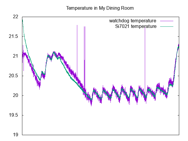
As you can can see, there is a bit of deviation at the very beginning (perhaps caused because the board itself had not been powered before, and therefore may not be subject to self-heating), and there are a couple of glitches, but overall the predicted value is a bit noisier, but tracks the temperature from the “real” sensor pretty well.
What’s left is to try to calibrate the sensor over a much larger temperature range, and to potentially determine how to compensate changing battery voltage if I were to power it from an unregulated source. But it seems like a completely viable way to do temperature sensing, at least if you take the time to calibrate the temperature against a known source (the same coefficients will not carry over between individual boards).
Addendum: The code above was pretty simple, but I did encounter one issue. I had been slowly adding functionality to the sketch, when suddenly code that had worked before began acting erratically, resetting the board and generally causing chaos. I spent about 20 minutes scratching my head, then went away and came back to it later. I then realized that what probably was happening was that I was nearing (or exceeding) the amount of RAM memory for the sketch. I hadn’t been using the ATmega328 in a while, and had forgotten that it only has 2K, so that’s actually pretty easy to do. In addition, the SdFat library consumes a fair amount of RAM as well, so you have to be careful. I did a few things to trim back memory consumption, and should go back and make sure that all the constant strings that I use for information printout are wrapped in the F() macro to make sure that they are stored in flash. If you do not do that, then they get copied into RAM, which is no good at all for memory consumption, and almost certainly not needed.