Arduino Bumper Shell, created with OpenSCAD
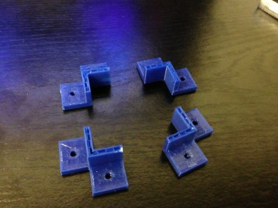
 Last week, I got a chance to experiment with a Replicator 2, and printed some brackets for my robot project. I designed them using OpenSCAD, which is kind of a scripting language for solid shapes. It can export in STL format, which I then used MakerWare to drive the Replicator 2. The picture at the right shows my first attempt, which aborted when my silly laptop went to sleep. Still, the brackets worked out pretty well. The holes in the bracket were coded to be 0.125″ in diameter, which is a loose clearance hole for #4 hardware. The resulting brackets actually were close to tap size: I could thread a screw into them, but not push one through it. That seemed like a pretty good test.
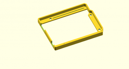
 While digging around for new stuff to make, I saw a “bumper” style case for the Arduino on Thingiverse. I thought that might an interesting project, and I needed something like this to mount my Arduino onto the robot platform I’ve been working on. In about an hour, I coded up one:
[sourcecode lang=”cpp”]
module arduino_outline() {
polygon([[0, 0],
[0, 2100],
[2540, 2100],
[2600, 2040],
[2600, 1590],
[2700, 1490],
[2700, 200],
[2600, 100],
[2600, 0]]) ;
}
module edge () {
difference() {
minkowski() {
arduino_outline() ;
circle(62.5) ;
}
minkowski() {
arduino_outline() ;
circle(8) ;
}
}
}
module bands() {
minkowski() {
square([2600, 200]) ;
circle(10) ;
}
minkowski() {
translate([0, 1900]) square([2600, 200]) ;
circle(10) ;
}
minkowski() {
polygon([[2600, 1590],
[2700, 1490],
[2700, 200],
[2600, 100],
[2500, 200],
[2500, 1490]]) ;
circle(10) ;
}
}
d = 31.25 ;
w = 16 ;
module bumper() {
difference() {
union() {
linear_extrude(height=250) edge() ;
linear_extrude(height=62.5) bands() ;
}
union() {
translate([550, 100]) cylinder(r=125/2., h=500, center=true) ;
translate([600, 2000]) cylinder(r=125/2., h=500, center=true) ;
translate([2600, 300]) cylinder(r=125/2., h=500, center=true) ;
translate([2600, 1400]) cylinder(r=125/2., h=500, center=true) ;
}
translate([-75, 125, 63]) cube([525, 300, 500]) ;
translate([-250, 1275, 63]) cube([625, 500, 500]) ;
translate([1100, 100, 62.5]) translate([-w, -w, -d]) cube([1400+2*w, 2*w, 2*d]) ;
translate([740, 2000, 62.5]) translate([-w, -w, -d]) cube([1740+2*w, 2*w, 2*d]) ;
}
}
scale([25.4/1000., 25.4/1000., 25.4/1000.]) bumper() ;
[/sourcecode]
I haven’t had the chance to print it yet, so it might not be exactly right for fit, but I’ll let you know how it works out.
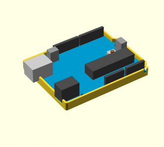
Addendum: I found a model for an Arduino in OpenSCAD, and tried merging it with my bumper. That revealed that I had made a mistake in the code listed above: the DC connector should be 350 mils wide: the slot as coded would be too narrow. I also decided to widen the relief channels for the pins which stick out the bottom, and provide an extra depth relief to support the DC and USB jacks. When I get a chance to print this out, I’ll probably upload the kit-n-kaboodle to thingiverse once I’m happy with it.
Until then, here’s the tease:
Addendum2: I experimented a bit with export options. I projected the bumper down to 2D, exported it as DXF, and then imported it into Inkscape, where I could convert it to a 300dpi bitmap. Voila.


I recall burning three or four weeks of a sabbatical getting Saccade.com on the air with Wordpress. So much tweaking…