New I2C peripheral: 6 DOF IMU, $5.89
 This little gadget arrived via Amazon Prime today: a three axis gyroscope/accelerometer that can be programmed via the I2C bus. I didn’t really have any reason to get one, other than simple curiosity, although I suspect that possibly mounting one on my (as yet unfinished) robot platform might be able to determine motion parameters of the robot.
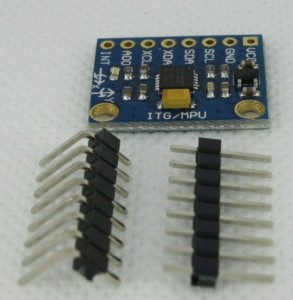
The board itself is well documented on the Arduino Playground as the MPU-6050 Accelerometer + Gyro. The pinout is rather simple: your normal +5 and GND, SDA and SCL (I2C bus serial data and clock) one address pin (which lets you decide between two addresses for the chip) and an interrupt pin. The chip includes a FIFO buffer, and whenever the chip places data in the FIFO, it triggers the interrupt, indicating that there is data available for reading. Additionally, the chip includes two other lines (XDA AND XCL) which are a separate I2C bus that the chip can use to talk to a magnetometer. Probably won’t be using that anytime soon, but you never know.
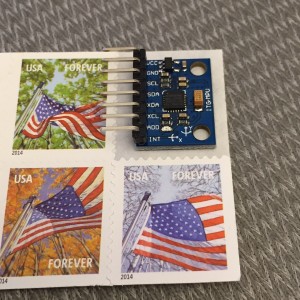
 As you can see from the picture, it’s really quite small, about the size of a postage stamp, and includes two mounting holes. When I get home, I think I’ll measure up the dimensions and put together the design for a little plastic case that can snap over it and provide some protection for it. The kit includes both right angle and normal headers, I think the right angle will do nicely.
More later.
Addendum: It’s later. Got the thing hooked up. It appears that I needed to ground the AD0 pin to set the address properly (I should double check this, I thought that if I left it floating, it would default to 0x69). Other than that, it’s dead simple. I wrote this code to get raw acceleration and gyro values from the sensor. I’m told that if you divide the raw values by 16384, you get the acceleration in terms of the gravitational acceleration “g”. In other words, if the board was lying perfectly flat on the tabletop, you’d expect that the X and Y accelerations were zero, and the Z would be 16384. Here’s a screen grab:
As you can see, I wasn’t really quite flat, mostly tilted in X. If you find the lengths of the acceleration vectors, you find it’s something like 0.92 g (we are off by 8% or so). I don’t know what the specs on this thing are, I’ll have to check the datasheet. I know that despite returning 16 bit values, it does not provide 16 bits of accuracy.
Anyway, here’s a simple test sketch:
[sourcecode lang=”cpp”]
//
// A short sketch to read data from the MPU-6050, aka the GY-51
//
// Cribbed from online sources by mvandewettering@gmail.com
#include <Wire.h>
const int MPU = 0x68 ; // I did ground the A0 pin…
int16_t acc_x, acc_y, acc_z ;
int16_t temperature ;
int16_t gyr_x, gyr_y, gyr_z ;
void
setup()
{
Wire.begin() ;
Wire.beginTransmission(MPU) ;
Wire.write(0x6B) ;
Wire.write(0) ;
Wire.endTransmission(true) ;
Serial.begin(9600) ;
}
void
loop()
{
Wire.beginTransmission(MPU) ;
Wire.write(0x3B) ;
Wire.endTransmission(false) ;
Wire.requestFrom(MPU, 14, true) ;
acc_x = (Wire.read() << 8) | Wire.read() ;
acc_y = (Wire.read() << 8) | Wire.read() ;
acc_z = (Wire.read() << 8) | Wire.read() ;
temperature = (Wire.read() << 8) | Wire.read() ;
gyr_x = (Wire.read() << 8) | Wire.read() ;
gyr_y = (Wire.read() << 8) | Wire.read() ;
gyr_z = (Wire.read() << 8) | Wire.read() ;
Serial.print("\e[2J\e[H") ;
Serial.println("RAW MPU-6050 DATA") ;
Serial.println() ;
Serial.print("ACCX ") ; Serial.println(acc_x) ;
Serial.print("ACCY ") ; Serial.println(acc_y) ;
Serial.print("ACCZ ") ; Serial.println(acc_z) ;
Serial.print("GYRX ") ; Serial.println(gyr_x) ;
Serial.print("GYRY ") ; Serial.println(gyr_y) ;
Serial.print("GYRZ ") ; Serial.println(gyr_z) ;
Serial.print("TEMP ") ; Serial.println(temperature / 340. + 36.53) ;
Serial.println() ;
delay(1000) ;
}
[/sourcecode]
Addendum2: Here is a library for accessing the MPU-6050 well (it can return quaternions for orientation, no gimbal lock!).

I recall burning three or four weeks of a sabbatical getting Saccade.com on the air with Wordpress. So much tweaking…