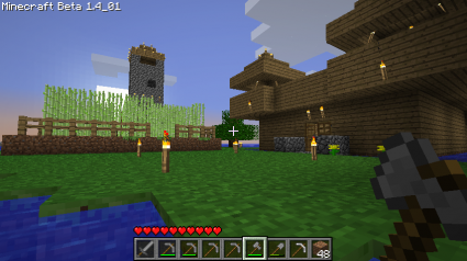
I was playing Minecraft with a few like-minded people the other day, and grew weary of excavating huge, deep holes and falling into lava pits. So, I decided to create my own little island reserve. I scouted a likely location: a small insignificant island off the coast from our main base and began construction.
Once my fort and light house were constructed, I tried to think of something else fun to do. I hit upon the idea of generating a maze, and then planting a garden on top. I recall that over thirty years ago, I wrote a series of programs for my Atari 400 to generate simple mazes on the screen. The basic idea was to create an array the size of the maze you wanted. In each square, you’d store one of three codes: it’s either a block, a square you’ve visited, or a square that has not yet been visited. Initially, you start in an unvisited square, and mark it as visited. You then pick a random starting direction, and see if the square in that direction has been visited. If it hasn’t, erase wall that connects you to it and recurse. If not, then proceed to the next direction until you’ve tried all four directions, then return.
It’s a simple recursive algorithm, which wasn’t really all that attractive on the Atari, which had limited ability for recursion (stack depth is severely limited on the 6502). So, instead of recursion, I stored the stack in the array itself: each square could hold a breadcrumb that told it where it should “back up to” when it had exhausted the current list of directions. But on modern computers, there really isn’t any need to complicate the code with that: I simply use ordinary recursion.
And… here’s the code. It was written in haste, so to write the .PNG it doesn’t even link with libpng: it simply opens a pipe to some of the netpbm utilities to rescale and convert the bitmap to a larger .png file.
[sourcecode lang=”C”]
#include <stdio .h>
#include <stdlib .h>
#include <unistd .h>
#define SIZE 80
#define ASIZE (2*SIZE+1)
char maze[ASIZE][ASIZE] ;
static int dx[] = {-1, 0, 0, 1} ;
static int dy[] = { 0, -1, 1, 0} ;
void
traverse(int i, int j)
{
int w, worig, x, y ;
maze[2*i+1][2*j+1] = ‘ ‘ ;
w = worig = lrand48() & 3 ;
do {
x = i + dx[w] ;
y = j + dy[w] ;
if (x>=0 && y>=0 && x<size && y<SIZE && maze[2*x+1][2*y+1]==’_’) {
maze[2*i+1+dx[w]][2*j+1+dy[w]] = ‘ ‘ ;
traverse(x, y) ;
}
w = (w + 1) & 3 ;
} while (w != worig) ;
}
main(int argc, char *argv[])
{
int i, j ;
int cnt ;
srand48(getpid()) ;
for (i=0; i<ASIZE; i++)
for (j=0; j<ASIZE; j++)
maze[i][j] = ‘#’ ;
for (i=0; i<SIZE; i++)
for (j=0; j<SIZE; j++)
maze[2*i+1][2*j+1] = ‘_’ ;
/* generate the maze */
traverse(0, 0) ;
for (i=0, cnt = 0; i<ASIZE; i++)
for (j=0; j<ASIZE; j++)
if (maze[i][j] == ‘#’)
cnt ++ ;
printf("%d blocks needed.\n", cnt) ;
FILE *fp = popen("pnmenlarge 4 | pnmtopng > maze.png", "w") ;
fprintf(fp, "P1\n%d %d\n", ASIZE, ASIZE) ;
for (i=0; i<asize ; i++) {
for (j=0; j<ASIZE; j++) {
fprintf(fp, maze[i][j] == ‘#’ ? "1 " : "0 ") ;
}
}
pclose(fp) ;
#ifdef MINECRAFT
/* now, print out the directions. */
for (i=0; i<ASIZE; i++) {
printf("begin row %d\n", i+1) ;
char ch = maze[i][0] ;
int chcnt = 1 ;
for (j=1; j<ASIZE; j++) {
if (maze[i][j] != ch) {
printf("[ ] %d %s%s\n", chcnt, ch == ‘#’ ? "block" : "space", chcnt > 1 ? "s" : "") ;
chcnt = 1 ;
ch = maze[i][j] ;
} else {
chcnt ++ ;
}
}
printf("[ ] %d %s%s\n", chcnt, ch == ‘#’ ? "block" : "space", chcnt > 1 ? "s" : "") ;
}
#endif
return 0 ;
}
[/sourcecode]
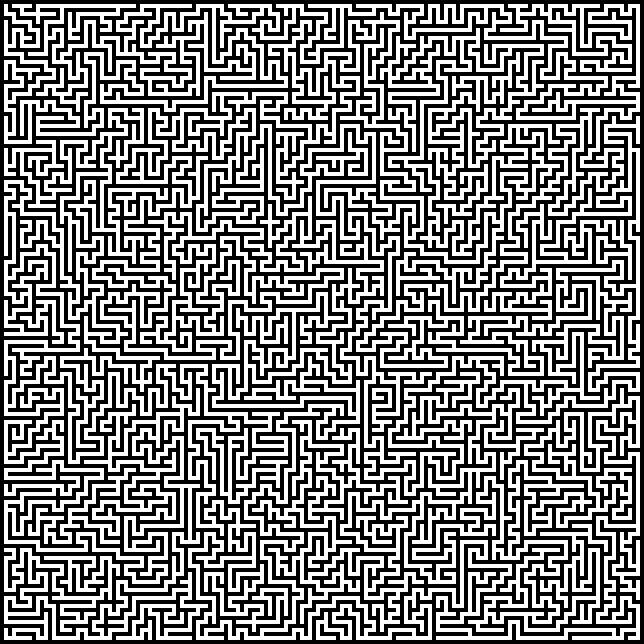
And here’s an example of the resulting maze:
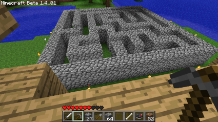
Of course a maze of this size would take years for me to complete in Minecraft, so I designed a much smaller one (the total size is about 15×15). I also added some code (which is ifdef’ed out above) to generate a list of instructions on how to reproduce the maze by constructing it in rows. If you define MINECRAFT before compiling, it will dump a list of instructions that look like…
begin row 1
[ ] 15 blocks
begin row 2
[ ] 1 block
[ ] 13 spaces
[ ] 1 block
begin row 3
[ ] 13 blocks
[ ] 1 space
[ ] 1 block
...
Using this, I constructed a small 15×15 maze which took 256 cobblestones (not including the roof):
Thinking about the program as I was driving in this morning, I thought about generating a maze that was suitable for poster size, maybe 1000×1000 in size or larger. I probably should go ahead an implement the recursion optimization I described, then the size of the mazes that could be generated would be limited only by memory. And, of course, I could implement some quick and easy “virtual memory” to allow generation of mazes that were as large as disk space could allow. I could also implement a number of other optimizations.
I was also thinking that this program didn’t really suggest method that would work with a functional programming language.
Tom suggested that one way to tackle it might be to create a graph with all the possible links and random weights connecting each pair of adjacent nodes. You could then solve it by any method that can solve the minimum spanning tree. Tom recently wrote similar code, so that’s probably why he thought of it. It just makes my head hurt.


