Monthly Archives: June 2015

More on my 8 digit clock, now with GPS synchronization…

Yesterday I just had a few minutes to hack around, and I decided to marry a sketch that used the TinyGPS++ library to the clock display that I had working the other day. I’ve been hopping back and forth between the Arduino and the Teensy LC as a development platform. Since I still had the display hooked up to an Arduino (actually the Sparkfun RedBoard, my favorite compatible) I decided to hook up the GPS to the RedBoard as well, to serve as the time source: the Arduino would wait until the GPS acquired a lock, and would then begin displaying the time.

Because the Arduino Uno (and RedBoard) have only a single dedicated serial port, the usual way to connect a GPS is to create a SoftwareSerial port using (say) pins 5 and 6. So, that’s what I did initially. It worked, but I found that whenever you did a Serial.read(), it caused a minor glitch in the timing of the refresh. At the beginning of each second, when the GPS squirts a substantial amount of text to be received, the entire clock display noticeably flickers since the Serial.read() messes with the timing of interrupts (presumably, by blocking them for a short but significant period of time). Bleh.

In the end, I ended up hooking the GPS pins to the hardware serial port on pins 0 and 1. The problem is of course that then the pins are unavailable for other uses, such as printing status back to your USB port, or (notably) downloading new code. I had to disconnect the GPS, flash the software, and then hook up the GPS again. The result was nice and smooth, no flicker.


A much better solution is to use a small board like the Teensy LC or Teensy 3.1. They each have three dedicated hardware serial ports in addition to the normal Serial device which can communicate back through the USB port. The Teensy 3.1 even includes hardware FIFO buffers, which will enable even more flexibility.

When I get some free time, I’ll probably include intermittent display of both latitude and longitude. Because I can, that’s why.
A simple clock, running on the Arduino Uno…

In a previous post, I wrote some interrupt driven code to refresh a multiplexed 8 digit, 7 segment display. Every 2 milliseconds, the Arduino triggers an interrupt, and then clocks out sixteen bits to a pair of chained 74HC595 shift registers, and then returns. That displays a single digit. The next interrupt displays the next digit, and so on until all eight are displayed. Because of persistence of vision, you don’t perceive any flicker, and you get a nice display.

Two things bothered me about the previous code: on a standard Arduino, it used about 18% of all available CPU cycles to do this refresh. That’s a lot of time to dedicate to just display. It’s not hard to see why: the code calls digitalWrite both directly, and because the shiftOut call also uses digitalWrite.

The problem is that digitalWrite is slow, really slow.

The reason is that while digitalWrite is slow, it’s actually doing an awful lot. At the hardware level, all the digital pins of an Arduino (which are numbered 0…13) are individual bits in one of several eight bit hardware ports. These ports are really just memory addresses. They have both a data direction register (which tells you whether each bit in the port is an input or an output) and a data register, which for inputs tells you whether associated pin is high or low, and which you can turn on individual bits to set outputs high or low.

On the Arduino Uno, pins 8-13 are attached to the lowest bits of the PORTB. You can assign byte values to PORTB, and the associated outputs will get driven high or low, all in one instruction. You can even set multiple bits at the same time,
which is impossible to do with digitalWrite.

So, why use digitalWrite?

It’s more portable. All Arduinos have pins 0-13, but some map them to different underlying PORTS (Arduino Megas for instance have more I/O ports, and a different mapping). By using digitalWrite, you don’t need to know which port corresponds to which pin, that’s all part of the library. The Teensy LC that I was testing with yesterday doesn’t even have the same underlying chip architecture, but the libraries to emulate the Arduino all behave perfectly, and I don’t have to change even a single line to get it to work with the Teensy. That’s pretty cool.

But it is pretty slow.

My testing yesterday showed that on the Arduino Uno, using digitalWrite meant that the critical part of the interrupt routine took 320 microseconds. The Arduino Uno runs at around 16Mhz, and can basically run one instruction per cycle, so that means it is taking about 5120 instructions just to clock out the sixteen bits into shift registers. Each bit requires about three output bits to get toggled, so that means that each toggle is around 100 instructions long.

I knew I could do better.

As I said, pins 8-13 are the low bits of PORTB. By directly accessing those bits, we can speed things up alot.

Without further explanation, here’s the old, short, portable code that calls digitalWrite and shiftOut routines:

[sourcecode lang=”cpp”]
void
LED_irq(void)
{
digitalWrite(latchpin, LOW);

// select the digit…
shiftOut(datapin, clockpin, MSBFIRST, col[segcnt]) ;
// and select the segments
shiftOut(datapin, clockpin, MSBFIRST, segbuf[segcnt]) ;

digitalWrite(latchpin, HIGH) ;
segcnt ++ ;
segcnt &= NDIGITS_MASK ;
}
[/sourcecode]

The faster version, which runs about 8x faster, but is not portable looks like this:

[sourcecode lang=”cpp”]
void
LED_irq(void)
{
PORTB &= ~0b00010000 ;

for (int i=0; i<8; i++) {
if (col[segcnt] & (0x80 >> i))
PORTB |= 0b00000100 ;
else
PORTB &= ~0b00000100 ;
PORTB |= 0b00001000 ;
PORTB &= ~0b00001000 ;
}

for (int i=0; i<8; i++) {
if (segbuf[segcnt] & (0x80 >> i))
PORTB |= 0b00000100 ;
else
PORTB &= ~0b00000100 ;
PORTB |= 0b00001000 ;
PORTB &= ~0b00001000 ;
}

PORTB |= 0b00010000 ;

segcnt ++ ;
segcnt &= NDIGITS_MASK ;
}
[/sourcecode]


If you want the complete code, you can get it from my github repository.

How much time is spent refreshing my 8 digit LED display?

A couple of days ago, I wrote about experimenting with a little Chinese 8 digit, 7 segment LED module that is driven by some 74HC595 shift registers. My initial experiment in driving it with the Teensy was successful: I got a nice, steady display with a simple interrupt driven scheme which displays each digit for two milliseconds before moving on to the next. But I wondered what percentage of my total time was actually being spent refreshing this display. In particular, how fast was the interrupt routine?

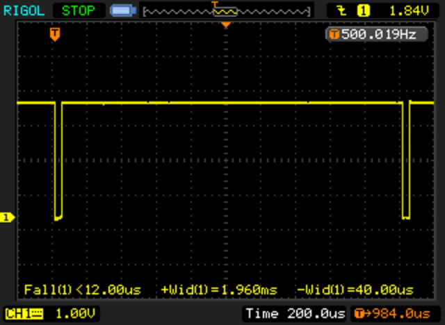
Most of the time spent in the interrupt routine is presumably spent in serially clocking out the individual bits to the shift register, using the Arduino library function shiftOut. I thought about adding some timers and computing what the time left, but this morning, I realized that I could use my nifty Rigol scope to figure out how long it took, by looking at the LATCH signal. Before clocking the data, the LATCH signal is brought low, and then afterwards brought high again. There are a couple of instructions on either side, but it’s not a bad approximation.

When I got home, I hooked up the scope.

NewFile2

Nifty! The total time accounts for 40 microseconds out of every 2000 microseconds, or about 2% of the total runtime for the Teensy. Nice! Works great. My guess is that it would be significantly more as a percentage with a traditional Uno. Perhaps I’ll try that out soon.

Addendum: I installed the same code on the Sparkfun Redboard (an Arduino Uno clone, which is an ATMEGA328 running at 16Mhz). With identical code, I used the same setup. The interrupt routine runs in about 360us, about 9x slower, consuming about 18% of the available CPU cycles. If you double the period to 4ms, you could halve this, but I find that the strobing of the ~33hz display to be slightly too much for me.

Modulo: A simple, modular solution for building electronics

A former colleague of mine, Erin Tomson, has been running a kickstarter that I’ve been meaning to talk about, but here it is, only a couple hours before the end of it, and she’s currently $382 short of her $50,000 stretch goal, and I haven’t written anything here. Sorry Erin! Anyway, I think of Modulo as what shields for the Arduino should have been: a cool way to plug a bunch of different controllers, sensors and display modules together to prototype or build electronic circuits. I had a great discussion with Erin at the Bay Area Makefaire just a few weeks ago, and it seems like a cool system. I think the system will be especially good for education. Even computers like the Raspberry Pi, which are nominally built for education don’t make the construction of additional circuitry and sensors particularly easy. This can definitely be a stepping stone to tinkering with computing as it relates to the physical world. I pledged in at the “Tea Time, Spark Edition” level, and am looking forward to testing it out.


If you’d like to get it on this, surf over and pledge. It’s a cool gadget, and it puts an engineer one step closer to doing other great cool stuff!

The Modulo.co website
The KickStarter page

Update: Whoohoo! She made her stretch goal! Congratulations, Erin!

More flying, with a couple of close mishaps…

I’m getting more confident flying the DJI Phantom 2, which means that I’m closer to having my first crash as I try to do more aggressive things. Mind you, the Phantom 2 pretty much has training wheels on it: no matter how hard you lean the stick to one side or the other, the copter will actually not doing anything blindly stupid. But still, immediately after launch, I flew across our soccer field and came closer to hitting the trees on the other side than I normally would like. After that, I just tried to do a bit of flying, doing overpasses of my head, trying to get used to turning left and right with the copter facing me and away from me… in general, just getting used to flying.

I did a couple of fun things: got a view of the 6′ tall seagull on top of one of our buildings, and a high angle shot of the main building here.


I did have one issue on this flight that’s hard to see: toward the end, I appeared to lose contact, and the copter took off to its “home location”, wherever that may be, but seemed to be toward our parking lot. A few seconds later, I managed to get control again and brought it back and landed without incident. Still, I should RTFM about how to set and recover from such an occurrence.

Driving an 8 digit, 7 segment display based upon the 74HC595…

A few weeks ago, I was scanning the Deal Extreme website, and ordered a few different LED displays, not because of any pressing need, but because I wanted to have some display options available if I needed some for a project. I was especially interested in cheap LED displays. One of the ones I ordered was this 8 digit, 7 segment display, which seemed to have a five pin interface. Without thinking about it too much, I went ahead and ordered it.

Today, they arrived. Like a lot of things that come from dealextreme, this one had been shipped somewhat haphazardly: the right angle header pins were significantly bent, but a little gentle prodding moved them back into place. I then spent a few minutes trying to decide what the module actually needed.

Unlike the modules I’ve had previously based upon the TM1637/TM1638/TM1640, these modules did not have a controller onboard that could latch all the segments and hold values. Instead, this board has 2 8 bit shift registers (namely, the 74HC595). Basically, one shift register controls which of the 8 digits are powered up (a high value in the 8 bit word indicates that the corresponding digit has a power on its cathode (which is common to all the segments of the LED) and the other 8 bit word tells it which segment is turned on (actually, it’s inverted: a 1 indicates the corresponding segment is off).

But here lies the rub: you only have 8+8 control lines, but you have to control 56 (actually 64 if you include the decimal points) segments. The way you get around this is to display a single digit at a time, but only do it for a short period of time. If you flip between digits fast enough, your persistence of vision will merge them into a consistent display.

The usual way to do this with an Arduino would be to use the shiftOut statement to clock the data out on some serial pins, and then call delay (or delayMicrosecond) to wait a bit, then shift the data out for the next digit, etc… But that makes the loop() difficult to write: you have to interleave both the display and all the other work that you have to do, with careful attention to timing.

There is a better way: interrupts. In particular, I used the TimerOne library (available on the Teensy as well as the Arduino libraries) to setup a timer interrupt. The idea is to contain a display buffer of 8 bytes, one byte per digit, which specifies which of the 8 segments is on. When the interrupt occurs, it clocks out the cathode and then the segments for the specified digit as quickly as it can, and then increments the display digit by one, wrapping around if necessary. Because this happens in an interrupt, it means that display happens without any real use intervention. When you want to change what is displayed on the display, you just change the contents of the segment buffer and then the interrupt fires next time, the appropriate digit will
be displayed.

The basic code worked the first time I typed it in (modulo plugging jumpers into the wrong pins on the Teensy, and with the digits occurring in the reverse order than I desired). A moments tweaking yielded this nice, steady display:

I’ve decided that rather than posting code fragments embedded here, I will instead post links to a github repository that holds the necessary code. As I extend and make improvements, you’ll be able to get updated code there.

Another day of flying… this time with the working gimbal…

At lunch today, I managed to get a quick flight in before the field was taken over by soccer players. Unlike my early attempt, this time the gimbal was working. The footage is not all that interesting, since I don’t have FPV setup, I can’t see what the camera is aimed at, which makes the framing hit and miss, but it is at least reasonably stable. I might try to tweak some of the settings for the gimbal, it moves very quickly when you try to tilt the camera up/down.

But I’ve completed five flights, still no crashes!