Monthly Archives: September 2011

Apologies to Ken and Eric re: SSTV Challenge…

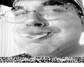
My face is red. I had claimed yesterday that nobody had tried to decode my SSTV challenge, when in fact both Ken and Eric decoded it. Eric was the first, who sent me this decode:

It’s a bit noisy, because he just played the sound file on his laptop and decoded it on a PC using the microphone inputs and running MMSSTV.

Eric followed about forty minutes later with his decode, again using MMSSTV.

Pretty neat.

I didn’t think that MMSSTV had the 8s mode in place, but sure enough, if you right click on one of the mode buttons, you can select an 8s B/W mode. It lists it as 160×120, which is keeping more in line with modern aspect ratios, and explains why my face looks squished. I will have to dig into the code a bit to see what it would take to make an encoder/decoder which is entirely compatible with what MMSSTV expects.

Thanks again, Ken and Eric, and apologies for not seeing your notes.

An impractical classic SSTV decoder…

A few days ago, I posted a .WAV file for a classic 8s SSTV image and asked if anyone could decode it. Nobody replied (I wasn’t surprised) so I set about writing my own demodulator.

Since I’m inherently lazy, here was my idea: generate the complex signal using my previously debugged Hilbert transform code. Then, for every adjacent pair of complex numbers, determine the angle between the adjacent samples by normalizing the numbers (so they have unit length) and then computing the dot product between the two. If you’ve done as much raytracing as I have, you know that the dot product of two vectors is product of their lengths and the cosine of the angle between them. So, you take the dot product, pass that through the acos function, and you’ll get an angle between 0 and $latex \frac{\pi}{2}$. You can then multiply that by the sample rate (and divide through by $latex 2\pi), and you can recover the frequency.

So, that’s what I did. If the frequency was in the band between 1500 and 2300 hz, I mapped that into a grayscale value. For values which were below 1500, I set the pixels to black. For values > 2300, I set the pixels to white. I generated one output pixel for every input sample. That means the image is too wide, but that’s no big deal: I resized it to 120 columns wide using some of the netpbm utilities (command line graphics programs).

And, here’s the image:

That’s a bit teeny, so let’s blow it up to 512×512:

Not too bad for a first try. Some thoughts: the sync pulses seem really wide to me. The spec says the sync pulses should be 5ms wide, which means they are about 7.5% as the line length. That’s a lot of the image to leave behind. I’ll have to work on that. I’m not currently doing anything to detect the vertical or horizontal sync pulses, but I’ve done that before with my NOAA weather satellite code, so I don’t anticipate any real problems. All in all, not a bad first try.

Addendum: The large image shows some JPEG compression artifacts since I expanded it from the small JPEG image without trying to save it at high quality. I can do better.

Addendum2: I decreased the overall filter size to length 11. It didn’t work very well, because the original file was at 22050, which pushes makes the portion of the spectrum we are interested in down into the region of the filter reponse which isn’t very uniform. But if we resample the sound file down to 8Khz, we filter works just fine with just 11 taps. Check it out:

The image is slightly skewed because the line length is no longer an integer number of samples, and the accumulated error causes the sync to drift slightly. A real implementation would track this accurately.

Difficulties with the Hilbert Transform…

Well, it wasn’t so much a difficulty with the Hilbert transform as a difficulty with my understanding. But with the help of my good friend Tom, my understanding was soon put right, and I thought it might make an interesting (in other words, horribly boring to anyone but myself) post, and at the very least, it would be good for me to document this little bit of mathematical fun.

Warning: complex numbers ahead!

This came up as a subtask of my slow scan television decoder. I’ll probably have a more detailed posting regarding the underlying theory, but the basic idea is as follows. The “pure” (without noise) SSTV signal is a frequency modulated signal with constant amplitude. But what does that really mean? After all, the instantaneous value of the signal varies: it’s a sine wave after all. What’s useful is to think of the analytic signal. Instead of being a single value at each moment in time, we think of a signal as a complex number, with a real and imaginary part. Let’s say the real part is $latex a$, and the imaginary part is $latex b$. The analytic signal can be represented as the complex number $latex a+b\imath$. The amplitude of the signal is then the $latex \sqrt{a^2+b^2}$.

If doesn’t make any sense to you, don’t fret. It’s mostly because we do a horrible job of teaching complex numbers, and I haven’t really done any better. You might be thinking, “what does this have to do with actual signals? The signals that I have are described by a single value, which varies over time. Why are you hurting my brain with complex numbers?”

In an attempt to stimulate you to think about it more, I’ll respond with the Socratic method, and as “what does the amplitude of a signal mean if they are described by only a single value?” In particular, how can you tell if a signal is “constant amplitude”? What does that even mean?

Okay, I’ll drop that topic for another time. Let’s just imagine that you accept my definition of constant amplitude, and we want to construct a complex signal from the real valued signal we receive from the radio. Let’s just pretend that the input signal gets copied into the real portion of the complex signal. In other words, the put values become the values for $latex a$ in our $latex a+b\imath$ above. For the purposes of our discussion, let’s say that the signal is some sine wave, $latex sin(t)$, where $latex t$ is a time variable (we could scale it to make it higher and lower frequency if we like). Let’s say the we’d like the amplitude of that signal is 1. Can we find values for $latex b$ that makes the amplitude $latex \sqrt{a^2+b^2} = 1$? If we square both sides, we see that $latex a^2 + b^2 = 1$, and since $latex a = sin(t)$, we see that $latex b^2 = 1-sin^2(t)$. If you remember any of your high school trig, you might remember that make $latex b = cos(t)$ ($latex sin^2(t) + cos^2(t) = 1$).

What this means is that for any given sine wave at a given frequency, we can get the complex version of the signal by copying a cosine signal of the same frequency into the imaginary part. If you think of cosine as just a phase with a 90 degree phase shift, you’ll see that if we had a magic filter that could make a 90 degree phase shift, you could easily construct the complex signal from the real signal.

But what if our signal isn’t made up of sine waves? Well, you can decompose the signal into the sum of a bunch of different sines (and cosines) of varying amplitude (proof left for the motivated reader). Applying the magic 90 degree phase shifter to all the sines, and then adding them back up, we’ll get the imaginary part of the signal we need.

None of this has anything to do with the problem really, it’s just background. It’s remarkably hard to explain this stuff to anyone who doesn’t understand it already, and I fear I’ve not done anything good. Oh well, onto my problem.

The way that you can implement the 90 degree phase shifter is by using some magic called the Hilbert transform, which can be implemented as an FIR filter. I wanted to create a black box that I feed values of my real signal in, and get (after some delay) the complex signal out. The code isn’t all that hard really, I’ll go ahead and put it here:

[sourcecode lang=”C”]
#include <stdio.h>
#include <stdlib.h>
#include <complex.h>
#include <math.h>

#define NZEROS (50)

static float xv[NZEROS+1];
static float yv[NZEROS+1];

static float xcoeffs[NZEROS+1] ;

double
window(int n, int N)
{
double a0 = 0.355768 ;
double a1 = 0.487396 ;
double a2 = 0.144232 ;
double a3 = 0.012604 ;

return a0 – a1 * cos(2.0 * M_PI * n / (N – 1))
+ a2 * cos(4.0 * M_PI * n / (N – 1))
– a3 * cos(6.0 * M_PI * n / (N – 1)) ;
}

void
oddhilb (float *hilb, int n)
{
float f;
int i, j, k, m;

m = j = k = (n – 1) >> 1;

for (i = 1; i <= m; i += 2) {
f = 2.0 / (i * M_PI) ;

hilb[j++] = 0.0;
hilb[j++] = f;
hilb[k–] = 0.0;
hilb[k–] = -f;
}
/* and now… window it…
*/
FILE *fp = fopen("unwindowed.dat", "w") ;
for (i=0; i<=n; i++)
fprintf(fp, "%lf\n", hilb[i]) ;
fclose(fp) ;

for (i=0; i<=n; i++) {
hilb[i] *= window(i, n+1) ;
}

fp = fopen("windowed.dat", "w") ;
for (i=0; i<=n; i++)
fprintf(fp, "%lf\n", hilb[i]) ;
fclose(fp) ;
}

complex
filterit(float val)
{
float sum;
int i;

for (i = 0; i < NZEROS; i++) {
xv[i] = xv[i+1];
yv[i] = yv[i+1];
}
xv[NZEROS] = val ;

for (i = 0, sum = 0.; i <= NZEROS; i++)
sum += (xcoeffs[i] * xv[i]);
yv[NZEROS] = sum ;
return xv[NZEROS/2] + I * yv[NZEROS] ;
}

main(int argc, char *argv[])
{
float f ;
complex c ;
int i ;
double t = 0. ;

oddhilb(xcoeffs, NZEROS+1) ;

for (i=0; i<4000; i++) {
f = sin(t) ;
t += 0.5 ;
c = filterit(f) ;
printf("%lf %lf\n", creal(c), cimag(c)) ;
// printf("%lf\n", cabs(c)) ;
}

}
[/sourcecode]

The program implements the Hilbert transform as an FIR filter. At each step, we compute a new value $latex f$ for our input signal. We then pass it to our filter stage, which returns our complex valued signal. If we then plot the real and imaginary parts of our signal, we should get a circle. And, in fact we do, now:

But when I started, I didn’t. The radius of the circle varied over quite a bit (maybe 10% or so). The reason was I forgot to apply the windowing function to the Hilbert transform filter coefficients. Plotting the two sets of coefficients, we see that the filtered versions fall to zero faster away from the middle.

We can use the FFT on these coefficients to see what the frequency response is.

You can see that the unwindowed filter has very uneven response over the range of frequencies, while the windowed signal is nice and flat over all but the region very near zero and the Nyquist frequency. This means that when we feed it nice sine waves, we’ll get a nice analytic signal with very constant amplitude.

Addendum(s): There is a small “off by one” error that adds an extra zero coefficient to the filters above. I’ll tidy it up a bit more when I get a chance. As Tom pointed out, for use in my SSTV decoder, it’s almost certain that just 11 coefficients would work just fine (and be faster). We could also optimize out the multiply by zeros in the convolution.
Classic Black and White SSTV timings?

I was trying to determine the exact timings for the classic “8 second” black and white SSTV mode. Copthorne MacDonald suggests 15 lines per second, to make 120 lines in 8 seconds. The vertical sync pulse has a duration of 30ms, and the horizontal sync pulse duration is just 5ms. The sync frequency is 1200Hz, and black and white interpolate between 1500Hz and 2300Hz. The aspect ratio is 1:1 (to match the usual oscilloscope tubes of the day).

So, I wrote a program to generate my best guess from this basic description, and here’s an example sound file:

An 8 second “classic” SSTV sound file, recorded as WAV File (22050Hz)

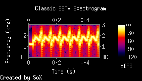
Here’s a spectrogram of the first 0.5 seconds or so, showing the vertical sync pulse, followed by a few scanlines:

I decided that the horizontal sync pulse should go in the final 5ms of each scanline (somewhat arbitrarilly).

So, the question of the hour is: can any modern software decode this basic image? I’ll be working on my own implementation, but I’m curious. I’ll leave it as a bit of a puzzle: if someone emails me the decoded image, you’ll be immortalized in these pages and have my thanks. Otherwise, you’ll just have to wait to see what the picture actually looks like in a day or so.

“Classic” Black & White SSTV…

I haven’t had much time for actual experimentation, but I have spent some time researching and some more time thinking about how to properly implement and test analog SSTV modulators and demodulators. I haven’t made much actual progress, but I thought I’d document some of the information that I’ve discovered and my current thoughts.

First of all, I began by trying to discover a bit of the history. Luckily, I’m an ARRL member, so I have access to all of the back issues of QST magazine. In this case, one only has to search for the author “Copthorne MacDonald” to find the 1958-1961 papers on the first amateur uses of slow scan television. I’m still perusing them a bit, but in the first paper, MacDonald suggested using a sub-carrier amplitude modulated signal which would be incompatible with virtually all SSTV modes used today, but in the 1961 he proposed the “classic” black and white, 8 second mode, consisting of 120 lines, frequency modulating between 1500 and 2300 Hz. These numbers were apparently chosen mostly for compatibility with existing telephone based fax standards of the day, but also nicely fit within the reasonably uniform region of most voice based transceivers in use for amateur radio.

This kind of “classic” black and white SSTV was apparently fairly common during the 1970s.

Here is some classic SSTV, re-rendered from a cassette recording done in 1980, documenting a QSO between KG4I in Birmingham, AL and N2BJW in Elmira, NY.

Here’s a clever way to say “Happy Trails” from AC5D:

Here’s a more modern implementation, which perhaps demonstrates a wider variety of imagery (a lot of it supermodels), still in the classic 120×120 black and white format:

Why bother with this simple mode? Well, just because it is simple. I also like the speed: the immediacy of the mode is kind of cool. I’m working on good, solid, easy to understand code to do this mode, and will post about my experiments in the presence of noise when I get some results.

Experiments with SSTV in the presence of noise…

Last night while watching television, I decided to code up an SSTV modulator for the most popular US mode, which is reportedly Scottie 1. I had done most of the heavy lifting when I created a Robot36 encoder a few years ago, so I mostly cribbed the meat out of that code, and modified it to do the details of Scottie 1, which (since it is in RGB space rather than YUV) is rather simpler than the original code. Once I had that working, I decided to do some experiments using Multiscan, an SSTV decoder that I had on my Macbook Pro.

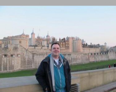
First, I needed some source material. I chose this picture of myself in front of the Tower of London, for no other reason than simple expediency. It does however have some nice features. It contains a faily uniform sky background, and then the tower itself is highly detailed, but with fairly low contrast. Here is the original, which was downsampled to 320×240, padded with 16 lines of gray, and then upsampled to an easier to view 640×512. Consider this the “ground truth” image. (Click on the image to view it full resolution)

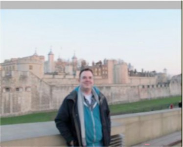
Using my modulator code, I then encoded it in Scottie 1 mode. I then used a loop back cable to play it back into the line input on my Macbook, and fed it to Multiscan, the better of the two programs that I know to do SSTV on the Mac. Here’s the resulting image:

Not exactly stellar. In fact, downright blurry. I wasn’t too pleased with the quality of this. My suspicion is that MMSSTV will do a better job, but I left my Windows laptop at work, so I can’t really be sure. It’s also possible (although I think somewhat unlikely) that my modulator is the source of the blurriness.

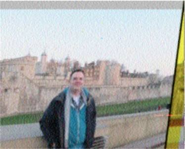
I also made a version of the audio file with some fairly strong additive white Gaussian noise added.

Multiscan wasn’t able to get the sync properly at this signal to noise ratio. I find that a little surprising, it seems to me rather straightforward to solve this problem. You can also see that the overall quality is quite a bit lower.

So, I’m curious: do any other SSTV decoders do better? In the interest of trying to find the best performing decoders, I will put links to the uncompressed 11025Hz .WAV files which I used for these tests. If you try them out with your favorite SSTV decoder, feel free to drop me an email with the decoded images (or links to them on flickr or picasa or whatever) along with details of what software you used, and whatever special operations or processing you did. If I get any good response, I will summarize in a future posting.

Scottie 1 SSTV, WAV format, 11025Hz sample rate, no noise.
Scottie 1 SSTV, WAV format, 11025Hz sample rate, substantial additive Gaussian white noise.

Thanks for any response! In the future, I’d like to do a more systematic evaluation of analog SSTV modulators, demodulators, and modes.

Addendum: For my reference on the implementation of modes, I used JL Barber’s excellent paper on SSTV modes. In his description of Scottie 1, he says that the first scanline has an anomalous sync pulse (9ms of 1200 Hertz). When I tried that with Multiscan, it never got started: it seemed to have some problem. When I deleted that sync pulse, everything starts as expected. If anyone tries this experiment, I’d like to hear of any failures to start. Also, if anyone knows of any definitive Scottie 1 examples on the web, let me know.

Thoughts on SSTV…

My recent playing with SSTV images coming from ARRISSat-1 have made me think a bit more about SSTV. I used two different applications to decode SSTV images (MMSSTV on Windows, and Multiscan on OS X), and got slightly different results in terms of performance from each. This leads me to ask “just what are the limits of performance for analog SSTV imagery, and how closely do existing applications approach these limits?”

Whenever I ask a question like this, there seems to be two complementary approaches: doing research and doing experiments.

Luckily, courtesy of Google, research has never really been easier. Relatively quickly I found this article by Lionel and Roland Cordesses:

Some Thoughts on “Real Time” SSTV Processing by Lionel and Roland Cordesses, QEX May/Jun 2003

It’s a great article, with many good ideas. The authors have apparently implemented them in the F2DC SSTV program, which apparently in need of some repair (written for Borland tools and Win95) but could provide the basis for a new, good implementation. But their paper provides some basic ideas, and I’m not sure I agree 100% with their implementation of them, so perhaps it is more valuable as inspiration.

They use a fairly old but still useful technique based upon the Hough Transform to do high quality deskewing of the incoming image signal. Much of the paper is devoted to details of making that work. In the past, I’ve used RANSAC to figure out sync pulse locations in my NOAA satellite decoder. Their technique is almost certainly less computationally intensive, but RANSAC can match more complex models (including Doppler shift, which is important for NOAA images), and I find RANSAC less “fussy” to implement (it is relatively indifferent to the model you choose, which makes modularization easier).

The other part of their paper deals with robustly estimating frequency. The simplest (and worse performing) demodulators estimate frequency from just two or three samples surrounding the current pixel location. The authors instead determine frequency by convolving a window function 37 samples long around the current position (they are sampling at 44100 samples per second) or about .83 ms. In the Martin-1 mode they use, a pixels is about .57ms long, so they are looking at a window of just about 1.5 pixels. That seems okay to me, but I’m confused by some of the choices.

They choose to digitize at 44100, which seems excessive to me. SSTV information is confined to the regions between 1200 and 2300 Hz, so according to the Nyquist theorem, even sample rates of 8Khz contain all the information needed to do a decode (assuming the signals actually are bandwidth limited). I was thinking of using 11025 samples per second. The corresponding window functions that would correspond to the 37 tap filter would be about 9 samples long, which would still provide the same level of frequency discrimination, but at a lower computational cost. I can’t imagine any practical reason to use finer sampling (DSP experts can point out any errors in my thinking in comments).

The cool part of their system is that they estimate the signal to noise ratio of the signal (by comparing power inside and outside the SSTV bandwidth) and use longer filters to estimate frequency when the SNR is poor. This makes a tradeoff between resolution and noise immunity, which seems in practice to be quite effective.

It would be interesting to make modern implementation, using gcc and fftw3 as a basis, and documenting all of the design choices. I think it would also be good to test the decoders against both AWGN (additive white Gaussian noise) and perhaps using an HF channel simulator to judge their performance. I’m most interested in the Robot36 mode, since that seems to be a common choice for satellites, but Scottie and Martin modes are also essential.

If anyone else has any interesting references on SSTV transmission and reception, feel free to add them via comments.

NOAA 19 recording, and atpdec…

Some of you may remember that I wrote my own APT satellite decoder. I ran across someone else who did the same:

ATPDEC by Thierry Leconte (F4DWV)

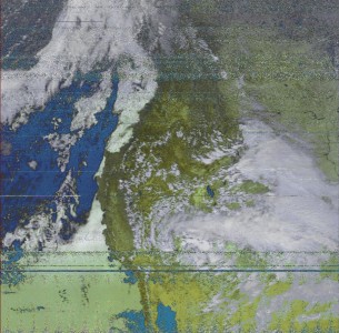
It has the same basic philosophy as my own crude efforts: hand it a WAV file, and it will find and produce the APT imagery from inside it. I went outside and recorded some of the NOAA 19 pass over my location today, and came up with the following:

Pretty nifty! I did have some trouble with some of the older recordings though: I suspect that noise may toss off his calibration in some way which isn’t entirely obvious. I’ll have to play with it more.

Shortwave Pirate Radio

I got pointed at this rather large collection of shortwave recordings which are archived on the archive.org website:

Shortwave Pirate Radio : Free & Unlicensed Shortwave Radio Stations : Free Download & Streaming : Internet Archive

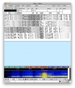
They have many crazy recordings of radio pirates, some of which are pretty dull, but some of which were pretty interesting. I was interested to find that there was a recording of a “digital” pirate radio station: station “XYZ”. It was easily recognizable to me as being transmitted in Hellscrieber, an old fax-like mode that was developed in the 1920s. The amateur software “fldigi” is capable of decoding these signals, which looks like this:

There is lots of fading in the recording, but it’s still quite legible. I’ve often thought making a small QRP Hellscrieber rig would be an awesome project. Oh well, I just thought it was mildly interesting.

Can we go beyond WSPR? An idea for beacon operations on amateur radio.

I was interested in WSPR and visual MEPT oeprations for quite some time. I operated both a beacon and a QRSS aggregator on 30m for a while, but I grew a bit tired of it, and it’s been silent for a year or so. But I haven’t stopped thinking about them. In fact, I’ve had an idea percolating in the back of my head since last year, when I became aware of the work of Leemon Baird and William Bahn on Jam Resistant codes.

But I’m getting ahead of myself. Here are some of what I think could be improved with WSPR:

  1. WSPR requires accurate clocks both for receiving and transmitting. To be successfully decoded, transmissions must start within a window just a few seconds long surrounding even numbered minutes. This makes both sending and receiving systems complicated: they probably need to access an external reference (NTP, GPS or WWV) to operate reliably over an extended period.
  2. Fixed frequency operation can cause collisions. Each transmitter selects a fixed transmit frequency, and relies on multiplexing over time to avoid collisions. WSPR software itself provides no real help in selection of an appropriate free frequency.
  3. The choice of a convolutional code is somewhat odd. The payload is only 50 bits long, but we pad the results with 31 zeros to flush out the convolutional coder. Thus, we are actually getting the error correction of a rate 1/2 code, but we are only sending as much data as if we were sending a rate 1/3 code.

I had been pondering some of these issues, when I became aware of the work of Baird and Bahn. They are researchers for the Air Force Academy, and were particularly studying the problem of providing jam proof communications without the need for shared secrets. Briefly, you can imagine using spread spectrum to provide a measure of jam proofing: because the data is spread out among many frequencies over time, the spread spectrum signal has a good measure of jam proofing: the jammer needs to put energy over most of the frequency most of the time, where as the transmitter can put his full power on just one frequency at a time (other variants of spread spectrum are a bit different, but the principle holds). The only way a jammer can work efficiently is by knowing the sequence, which is usually a cryptographic secret.

This is where Baird, Bahn, and Collins’ work comes in: In their paper:

Baird, Leemon C. III, Bahn, William L. & Collins, Michael D. (2007) Jam-Resistant Communication Without Shared Secrets Through the Use of Concurrent Codes, Technical Report, U. S. Air Force Academy, USAFA-TR-2007-01, Feb 14.

they show a simple technique that can be used to transmit signals with high reliability and a high degree of jam resistance, without requiring any kind of shared secret or cryptography.

The idea is somewhat subtle, but reasonably straightforward. The idea is to create take the binary message (say, the same 50 bits that we use for WSPR). This message gets padded by a series of zeros (maybe lots of them, perhaps a multiple of the original message length). You then need a hash function (some details matter, but you can think of using a standard one like MD5 or one of the SHA variants if you like). Now, for each prefix of the message (bit streams of length one, then two, then three, and so on), you compute the hash of that prefix. Let’s say that you are going to transmit the message by sending short, powerful bursts of energy at particular times in particular window. (You can imagine this being the two minute window used to transmit WSPR to make it more practical). If we divide that into (say) 8192 slots, then we could take each hash, take the lower 13 bits, and use that to specify a particular time when that bit would get turned on. If we send 500 bits total (9 zero checksum bits) for every real one, we are sending about 500/8192 slots, or about 6% of the total. To mark the start and stop, let’s turn on the first and last bit. That’s pretty much the entire transmit side.

What’s cool is that you can decode the message on the remote side, and if you ignore efficiency, it isn’t even that hard. Let’s say that you located a stretch of bits 8190 long, between two on bits. That might be a message. So, how do you decode it? Well, the first bit might be a zero or a one. You basically pretend that you are transmitting, and encode both messages. That will return a location, which you check to see is on. If it isn’t, then you know that guess was wrong. If it is, then that hypothesis is good. It’s possible that none could be right. That means there is probably not a message in that span. It’s possible that one could be right, in which case you then add a zero, and then try adding an one, and seeing if the hypothesis still holds. There are times when both results will check out, but statistically it is unlikely. When you hit the “checksum bits”, you know that there is only one possibility: a zero. If the specified hash doesn’t yield a location that is turned on, you know that you are on the wrong track. (The overall algorithm reminds me somewhat of a Viterbi style decoder, although it is actually considerably simpler).

There are lots of details to make this efficient (you want a hash function which allows incremental updates as you add individual bits to the message) but it’s pretty straightforward.

Anyway, I think this could be the basis for a new highly-collision resistant beaconing protocol for amateur radio. It would enable very simple transmitters (a simple microcontroller could hold the sequence in internal EEPROM, no need for highly accurate clocks) and the system would be more highly jam resistant than the current system. We could use simple CW transmissions, or adapt to slower rates with more diverse frequency usage. And, the technology has been paid for by your tax dollars, so no pesky patent/IP issues would seem to apply.

What do people think? I’m interested in hearing some feedback from digitally minded radio amateurs.

Addendum: if my descriptionw as insufficient, try reading the papers (especially Visually Understanding Jam Resistant Communication) and/or posting some questions in the comments.

Morning ARISSat-1 SSTV

I overslept this morning, and woke up a scant 10 minutes before this morning’s good pass of ARISSat-1 was to begin. Still, all I had to do was go out to my car, grab my Arrow, and my HP laptop, and my trusty VX-3R, and I should be able to make it. I started pulling on my shorts and shoes, and then remembered that my HP laptop had not been plugged in, and the amazing penchant for laptops to discharge when not fully shut down would mean that it was likely it’s battery was dead. No problem, think I. “I’ve still got my Macbook, and it was plugged in.”

I quickly fired up the Macbook and reacquainted myself with the pass. Yep, should start in about 4 minutes, peaking at 72 degrees or so. Nice! I grab my car keys and head outside to fetch a camp chair, my Arrow antenna and the radio.

But when I pop the back, I find that unlike what I expect, my VX-3R isn’t there. I can’t remember: did I bring it in to be recharged? Oh well, I have my VX-8GR which I use in my car as well, and that’s fully charged up. I quickly shift it over to 145.950, and attach it to the Arrow. Even though the antenna is aiming straight down I can still easily hear the voice from the beacon coming in. I scramble for a little patch cable so I can get it hooked to the laptop.

Then I remember: unlike the VX-3R, the VX-8GR has a combination speaker/microphone output, and the normal patch cable that I use with great success on the VX-3R doesn’t work on the VX-8GR. I need some crazy adapter, which I may or may not have. Sigh. On well. I shift Audacity over to record from the laptop microphone (meaning I’ll get road noise from passing cars, and wind noise) but that’s the only way that I will salvage the pass.

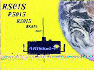
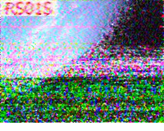
I got two SSTV images, as well as some nice recordings in French and Japanese. Sadly, but somewhat predictably, the best image was the standard logo, and the more interesting image was happening as the satellite was approaching the horizon. Still, best I’ve gotten in a while.

The horizontal bar in this one was caused by a gust of wind. Still, not bad.

Toward the end of this one, I was losing the signal pretty badly. I’ve used lots of noise reduction, which helped a tiny bit.

I’ll try to be better for tonight’s high pass.

Addendum: I found the little pigtail doohickey (a Yaesu CT-44, in case you need one) in an astoundingly short period of time. The way that ham radio equipment manufacturers pad their margins by requiring custom cabling (this little gadget costs around $15 from HRO) is shameless. Not only do I have to pay for it, but I have to remember to keep it in my equipment bag for the times I need it. Argh. Oh well, I’ll have it ready for tonight’s pass.

8080 bottles of beer…

Okay, not 8080 bottles, but 99 bottles of beer anyway…

[proof:~/adad] markv% ./adad
::: brainwagon 8080 emulator version 1.0
::: 637 bytes of code loaded.
99 bottles of beer on the wall, 99 bottles of beer.
Take one down, pass it around, 98 bottles of beer on the wall.
98 bottles of beer on the wall, 98 bottles of beer.
Take one down, pass it around, 97 bottles of beer on the wall.
97 bottles of beer on the wall, 97 bottles of beer.
Take one down, pass it around, 96 bottles of beer on the wall.
96 bottles of beer on the wall, 96 bottles of beer.
Take one down, pass it around, 95 bottles of beer on the wall.
... output trimmed for the sake of brevity ...
5 bottles of beer on the wall, 5 bottles of beer.
Take one down, pass it around, 4 bottles of beer on the wall.
4 bottles of beer on the wall, 4 bottles of beer.
Take one down, pass it around, 3 bottles of beer on the wall.
3 bottles of beer on the wall, 3 bottles of beer.
Take one down, pass it around, 2 bottles of beer on the wall.
2 bottles of beer on the wall, 2 bottles of beer.
Take one down, pass it around, 1 bottle of beer on the wall.
1 bottle of beer on the wall, 1 bottle of beer.
Take one down, pass it around, no more bottles of beer on the wall.


::: 53132 cycles counted.
::: 0.00 seconds elapsed.
::: 0.03 seconds on a 2Mhz 8080.
::: 11.50 x speedup.