I move my pretty useless blog to Hugo about 7 years ago, since I got frustrated at too many security…
Using a SainSmart LCD panel with the Arduino 1.6.3 IDE…
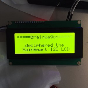
 Yesterday I experienced some frustration with the SainSmart I2C LCD Module that I bought to help Pete and Bill uncover the problems that they’ve been having. If you go and read, you’ll find that I had a lot of difficulty finding the right combination of code that can be used with this module. Eventually, I figured out how to use it, so I thought I’d document it here, to avoid the pain that someone else may feel.
The basics are essentially this:
- The LiquidCrystal library that ships with I2C is probably fine for connecting to LCDs with a parallel interface, but it does not support I2C bus displays.
- There is a so-called “New” or “FM” version of the LiquidCrystal library that you can find documented here. You can download the code by clicking here. I tested LiquidCrystal_V1.2.1.zip while typing this up.
- The new library is viewed as a replacement for the existing library. That means that you have to delete the existing library from the 1.6.3 libraries directory, and add the LiquidCrystal library in its place. This is kind of a pain, and is the worst part of this procedure. The instructions are here, but not very explicit. The commands you type also vary a bit with what operating system you use. Basically, the idea is to find the directory where the Arduino system libraries are installed, and delete (maybe after backing up) the LiquidCrystal directory, and replace its contents with the new LiquidCrystal directory. You’ll have to shutdown and restart the Arduino IDE after making the change.
And, you are almost home. You’ll have to make a couple of small changes to your sketches to make them use the I2C LCD display. Instead of including “LiquidCrystal.h”, you’ll need to include “LiquidCrystal_I2C.h”. And, you’ll need to make a small change to the “constructor” that builds the LCD object.
#include "LiquidCrystal_I2C.h"
#define BACKLIGHT_PIN (3)
#define LED_ADDR (0x27)  // might need to be 0x3F, if 0x27 doesn't work
LiquidCrystal_I2C lcd(LED_ADDR, 2, 1, 0, 4, 5, 6, 7, BACKLIGHT_PIN, POSITIVE) ;
And then you should be able to use the “lcd” object just like any other. If you look at this page, you can see all the operations that the lcd object supports. If you ever want to use (say) a parallel interfaced LCD, you’ll probably be able to do so by just changing the include and the constructor.
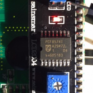
Bonus explanation: You are probably asking “what’s with all that the numbers in that constructor?” and “why those numbers?” and “what do they mean?” Here’s the basics (the details are not that important). The “piggyback” board that we use is mostly a chip that we call an “I2C I/O expander”. If you look carefully, you can read the part number off the chip. In this case, it says that it’s a PCF8574. A little Googling will reveal that it’s a chip made by Texas Instrument, and it basically has a set of data pins that can be individually configured as inputs and outputs, and read and written by commands sent over the I2C bus. The little backpack connects each one of those outputs to a particular pin on the LCD board. The library (you can think of it as a driver) is basically the code that knows how to send commands over the I2C lines, that causes each of the eight or so pins on the PCF8574 to go high or low, and thereby activating functions on the LCD.
There are a couple of complications that can arise. First of all, while the PCF8574 is a common chip, there are similar backpacks you can buy that might use different (but similar chips). If your backpack doesn’t have a PCF8574 on it, you may find that my code above doesn’t work, and you’ll have to figure out what’s happening on your own.
But even if it does, there appear to be incompatibilities between some backpacks as well. As I mentioned before, some appear to have the address 0x27 (like mine) but some might have the address 0x3F. I’m not sure why that may happen (perhaps they are using a “work-a-like” chip whose real only difference is the I2C Address it response to?)
But the major problem is that even if they use the same chip, they need to wire the circuit to the LCD in the same way. I’ll try to explain. Let’s say the I/O expander has 8 output pins, which we will label P0 through P7. They all have similar capabilities. To drive the LCD parallel inputs, we need to wire them up. One of the LCD pins controls the backlight. Which of the I/O expander outputs should we wire to it? It’s actually arbitrary, we could pick whatever we like. But to turn on the backlight, we need to know which choice was made (which of the P0-P7 we need to turn on), and the same goes for all the other pins that we need write. Thus, the software needs to know how the wiring of this little backpack is setup.
And sadly, it appears that there might be different boards, with different wiring. Luckily, in this new LiquidCrystal library, they foresaw this eventuality, and allowed you to specify how those things are wired up. If you look in the file LiquidCrystal_I2C.h, you’ll see a definition for the constructor that we are using:
  // Constructor with backlight control
   LiquidCrystal_I2C(uint8_t lcd_Addr, uint8_t En, uint8_t Rw, uint8_t Rs,
                     uint8_t d4, uint8_t d5, uint8_t d6, uint8_t d7,
                     uint8_t backlighPin, t_backlighPol pol);
This looks a bit daunting, but what it means is that you can specify an LCD panel by specifying a bunch of values. The uint8_t is just an ugly shorthand for a small integer (an unsigned value, ranging from 0-255). The first argument is the I2C address (0x27 in the case of my board). The next arguments are which I/O pin on the I/O expander goes to the named pin on the LCD board. For example, in our case, the next argument after the address was a 2. That means that P2 of the I/O expander is wired to En (the enable pin) on the LCD board. Similarly P1 goes to the Read/Write Pin, and so on. The final two arguments say that the backlight was wired to P3, and that it’s polarity is POSITIVE (some displays have the LED turn on when the pin goes to ground).
So, how did I figure out which pin goes to which? If you had a schematic for the board, you could work it out using datasheets. I actually got lucky, and realized that the example sketch on the SainSmart product page had an example sketch which included these lines. The code they posted there is not compatible with the 1.6.3 IDE (sigh) but the information was helpful.
So, it took WAY too much time, and WAY too much work, but I have it working. Hope that helps someone else who comes along later.
Comments
Comment from David R Hassall
Time 4/23/2015 at 6:48 am
Thanks for all the work Mark. I have been wanting to use that larger readout in a
number of projects here… but didn’t have the skill or the guts to tackle getting
it to work. I have been dormant for a while with Ardunio projects and need to get
back into it. I haven’t seen your signal on the QRSS bands for a while either.
Take care and have fun… My other life is a MESH!
73 Dave
Comment from Jeff Whitlatch – ko7m
Time 4/23/2015 at 9:08 am
Mark, having been a follower of your blog for years, I feel your pain. This is a bit of preaching to the choir, but here goes…
While these LCD panels are pretty ubiquitous and fortunately use, for the most part, the same chipset, the same cannot be said about these i2c backpacks. Your analysis is spot-on. While the good folks that produce the Arduino IDE have done a great job building a rather comprehensive development environment that is still friendly to folks who don’t have SDE as the day job, it is a really tall order to try to be all things to all people (26 years at Microsoft taught me that if nothing else).
When we start to build these embedded systems it is a process that fortunately (or unfortunately depending on your point of view) includes selections on the part of the builder/maker/engineer of hardware components. As you pointed out, as an engineer making these decisions with datasheets in hand and schematics of in-house or external board candidates, building the software to support it is pretty straight-forward, if not tedious. Probably beyond the abilities of someone new to microcontrollers and/or software development however.
One thing I might suggest adding to your list of suggestions for success for young players would be to not rely on libraries continuing to work long term, or even being available for download. These sites come and go with the wind it seems and that initial pain you felt of selecting an initial candidate is very difficult if not impossible to make go away due to both the pain of and the beauty of decentralized development of these widgets.
If you are going to adopt a particular library that you have found (mostly) suits your needs (hopefully for multiple projects) then make the source code your own. Build a collection of what works for you and be sure to debug it with each new release of the IDE that is going to blow away anything your installed in it’s directory structure. I suggest using source control sites like github to version your changes and to make it easy to share back to the community. Post your updates and bug fixes, but version and keep your schematics and datasheets that you depend on as well.
Evaluate new IDE releases and for new functionality that may overlap with your built-up collection of libraries you depend on and if the functionality can be replaced by a standard IDE library, you can consider dropping your own library and adopting the standard, recognizing that you give up control of your destiny for that particular functionality.
Anyway, sorry for the pain, but thanks for the great write-up.
Comment from Pete Juliano
Time 4/23/2015 at 9:55 am
Hi Mark,
Thanks for your hard work on this. It is now nice to see that displays will work with V1.6.3
Pete N6QW
Comment from Alan
Time 4/23/2015 at 12:08 am
There’s a helpful page about the I2C backpacks here:
https://arduino-info.wikispaces.com/LCD-Blue-I2C
You appear to have the ‘Type 1’. ‘Type 3’ is common here in the UK.