How much time is spent refreshing my 8 digit LED display?

June 2, 2015 | Arduino, Teensy | By: Mark VandeWettering

A couple of days ago, I wrote about experimenting with a little Chinese 8 digit, 7 segment LED module that is driven by some 74HC595 shift registers. My initial experiment in driving it with the Teensy was successful: I got a nice, steady display with a simple interrupt driven scheme which displays each digit for two milliseconds before moving on to the next. But I wondered what percentage of my total time was actually being spent refreshing this display. In particular, how fast was the interrupt routine?

Most of the time spent in the interrupt routine is presumably spent in serially clocking out the individual bits to the shift register, using the Arduino library function shiftOut. I thought about adding some timers and computing what the time left, but this morning, I realized that I could use my nifty Rigol scope to figure out how long it took, by looking at the LATCH signal. Before clocking the data, the LATCH signal is brought low, and then afterwards brought high again. There are a couple of instructions on either side, but it’s not a bad approximation.

When I got home, I hooked up the scope.

NewFile2

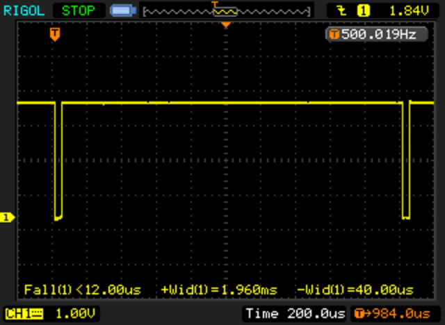
Nifty! The total time accounts for 40 microseconds out of every 2000 microseconds, or about 2% of the total runtime for the Teensy. Nice! Works great. My guess is that it would be significantly more as a percentage with a traditional Uno. Perhaps I’ll try that out soon.

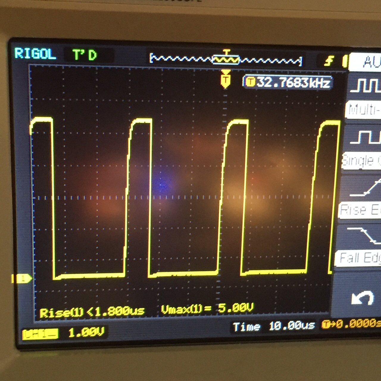
Addendum: I installed the same code on the Sparkfun Redboard (an Arduino Uno clone, which is an ATMEGA328 running at 16Mhz). With identical code, I used the same setup. The interrupt routine runs in about 360us, about 9x slower, consuming about 18% of the available CPU cycles. If you double the period to 4ms, you could halve this, but I find that the strobing of the ~33hz display to be slightly too much for me.

Modulo: A simple, modular solution for building electronics

June 2, 2015 | Kickstarter | By: Mark VandeWettering

A former colleague of mine, Erin Tomson, has been running a kickstarter that I’ve been meaning to talk about, but here it is, only a couple hours before the end of it, and she’s currently $382 short of her $50,000 stretch goal, and I haven’t written anything here. Sorry Erin! Anyway, I think of Modulo as what shields for the Arduino should have been: a cool way to plug a bunch of different controllers, sensors and display modules together to prototype or build electronic circuits. I had a great discussion with Erin at the Bay Area Makefaire just a few weeks ago, and it seems like a cool system. I think the system will be especially good for education. Even computers like the Raspberry Pi, which are nominally built for education don’t make the construction of additional circuitry and sensors particularly easy. This can definitely be a stepping stone to tinkering with computing as it relates to the physical world. I pledged in at the “Tea Time, Spark Edition” level, and am looking forward to testing it out.


If you’d like to get it on this, surf over and pledge. It’s a cool gadget, and it puts an engineer one step closer to doing other great cool stuff!

The Modulo.co website
The KickStarter page

Update: Whoohoo! She made her stretch goal! Congratulations, Erin!

More flying, with a couple of close mishaps…

June 2, 2015 | Quadcopter | By: Mark VandeWettering

I’m getting more confident flying the DJI Phantom 2, which means that I’m closer to having my first crash as I try to do more aggressive things. Mind you, the Phantom 2 pretty much has training wheels on it: no matter how hard you lean the stick to one side or the other, the copter will actually not doing anything blindly stupid. But still, immediately after launch, I flew across our soccer field and came closer to hitting the trees on the other side than I normally would like. After that, I just tried to do a bit of flying, doing overpasses of my head, trying to get used to turning left and right with the copter facing me and away from me… in general, just getting used to flying.

I did a couple of fun things: got a view of the 6′ tall seagull on top of one of our buildings, and a high angle shot of the main building here.


I did have one issue on this flight that’s hard to see: toward the end, I appeared to lose contact, and the copter took off to its “home location”, wherever that may be, but seemed to be toward our parking lot. A few seconds later, I managed to get control again and brought it back and landed without incident. Still, I should RTFM about how to set and recover from such an occurrence.

Driving an 8 digit, 7 segment display based upon the 74HC595…

June 1, 2015 | Arduino, My Projects, Teensy | By: Mark VandeWettering

A few weeks ago, I was scanning the Deal Extreme website, and ordered a few different LED displays, not because of any pressing need, but because I wanted to have some display options available if I needed some for a project. I was especially interested in cheap LED displays. One of the ones I ordered was this 8 digit, 7 segment display, which seemed to have a five pin interface. Without thinking about it too much, I went ahead and ordered it.

Today, they arrived. Like a lot of things that come from dealextreme, this one had been shipped somewhat haphazardly: the right angle header pins were significantly bent, but a little gentle prodding moved them back into place. I then spent a few minutes trying to decide what the module actually needed.

Unlike the modules I’ve had previously based upon the TM1637/TM1638/TM1640, these modules did not have a controller onboard that could latch all the segments and hold values. Instead, this board has 2 8 bit shift registers (namely, the 74HC595). Basically, one shift register controls which of the 8 digits are powered up (a high value in the 8 bit word indicates that the corresponding digit has a power on its cathode (which is common to all the segments of the LED) and the other 8 bit word tells it which segment is turned on (actually, it’s inverted: a 1 indicates the corresponding segment is off).

But here lies the rub: you only have 8+8 control lines, but you have to control 56 (actually 64 if you include the decimal points) segments. The way you get around this is to display a single digit at a time, but only do it for a short period of time. If you flip between digits fast enough, your persistence of vision will merge them into a consistent display.

The usual way to do this with an Arduino would be to use the shiftOut statement to clock the data out on some serial pins, and then call delay (or delayMicrosecond) to wait a bit, then shift the data out for the next digit, etc… But that makes the loop() difficult to write: you have to interleave both the display and all the other work that you have to do, with careful attention to timing.

There is a better way: interrupts. In particular, I used the TimerOne library (available on the Teensy as well as the Arduino libraries) to setup a timer interrupt. The idea is to contain a display buffer of 8 bytes, one byte per digit, which specifies which of the 8 segments is on. When the interrupt occurs, it clocks out the cathode and then the segments for the specified digit as quickly as it can, and then increments the display digit by one, wrapping around if necessary. Because this happens in an interrupt, it means that display happens without any real use intervention. When you want to change what is displayed on the display, you just change the contents of the segment buffer and then the interrupt fires next time, the appropriate digit will
be displayed.

The basic code worked the first time I typed it in (modulo plugging jumpers into the wrong pins on the Teensy, and with the digits occurring in the reverse order than I desired). A moments tweaking yielded this nice, steady display:

I’ve decided that rather than posting code fragments embedded here, I will instead post links to a github repository that holds the necessary code. As I extend and make improvements, you’ll be able to get updated code there.

Another day of flying… this time with the working gimbal…

June 1, 2015 | Pixar Animation Studios, Quadcopter | By: Mark VandeWettering

At lunch today, I managed to get a quick flight in before the field was taken over by soccer players. Unlike my early attempt, this time the gimbal was working. The footage is not all that interesting, since I don’t have FPV setup, I can’t see what the camera is aimed at, which makes the framing hit and miss, but it is at least reasonably stable. I might try to tweak some of the settings for the gimbal, it moves very quickly when you try to tilt the camera up/down.

But I’ve completed five flights, still no crashes!


Some reliability problems with my DS3231…

May 31, 2015 | Amateur Radio, Arduino, Teensy | By: Mark VandeWettering

I was working on some additional software to power my nascent WSPR project. I’ve been thinking that rather than using an Arduino, it would be better to use the Teensy, so I’ve been experimenting a lot with the Teensy LC. My idea was to wire up my Ultimate GPS and an I2C based DS3231, and then write a sketch that powers up the GPS, attains a fix, and then uses the time to set the time on the DS3231. It then will periodically wake up the GPS and check the time as reported by the DS3231 against the GPS.

But I’m having some difficulty. The GPS part works just fine, but when I try to do the first write to the DS3231 to set the time, it occasionally hangs. The way these libraries are written, the writes never time out, and the exchange grinds to a halt.

I’m not sure what’s going on here. Could be a bug/issue in the library, or something having to do with the Teensy Wire library, or the pull-ups. The rise times seem very slow.

graph2
I’ll keep playing around to figure out what the deal is.

Addendum: This seems relevent but the code is only for real Arduinos, and probably needs some tweaks to work with the Teensy. I am curious as to whether the delay itself may be enough to help.

Farewell…

May 28, 2015 | My Diary | By: Mark VandeWettering

You’ve probably heard the expression that somebody is a “man of few words”. I’m not that guy. I’m a man of many words. I love to talk. I love to write. And yet, it is an odd paradox that when you actually feel like you have something to say, the words fly from you, leaving you unable or unwilling to communicate.

Today, we had to say goodbye to Scrappy, our little gray striped American shorthair:

IMG_5314

I write this blog (in part) as a kind of a message-in-a-bottle to my future self.  On the anniversary of a post, it recirculates in the side bar on the left.  Usually it reminds me of some project I did (and likely abandoned).  Or something that I was interested in.  A year from now, what am I going to want to remember?

He had the most beautiful green eyes.  He never stopped trying to learn to speak.  He would look you right in the eye and patiently meow at you repeatedly until you understood what he wanted you to do.

He knew he was part of our family.  In the evening when we’d be watching TV, he’d find a place between Carmen and me, either on the couch or on the folding footrest of our recliner and would sit and sleep while we watched TV.   If we went upstairs, he’d do the same, until we turned the TV off and then he’d wander off.

Despite being deadly to birds, lizards, and dangerous to other cats, he never scratched or bit at humans.  Even when when we gave him a bath, or had to put him in a box to take him to the vet, he would struggle, whine, or complain, but never hiss, never bite, never scratch.   And after we’d finish bathing him, he’d get over it immediately, knowing that we were just trying to help him.

He purred a lot.  He could meow loudly and insistently.  Especially in the morning when I was late feeding him.

He was smart.  He learned to raise his paw to beg for special treats.

He loved catnip and to play with his orange shoe lace.

Yesterday he was outside, sniffing at the grass, just sniffing.  He loved sunshine and fresh air.  While we may have converted him from a mostly feral outdoor cat into an indoor kitty, he always loved to be outside.

We were with him at the end.

He was special.  He was loved.  He is missed.


A 4 digit, 7 segment display board based upon the TM1637 chipset…

May 28, 2015 | Arduino, My Projects | By: Mark VandeWettering

Yesterday, I got a small 4 digit, 7 segment LED display board in the mail from dx.com. Cost was around $3 shipped, and the module uses a 4 pin interface (power, ground, clock and data). Originally, I thought it was I2C, but like other modules I have received based upon chipsets made by Titan Micro (using the TM1638 and TM1640) it looks superficially like I2C, but doesn’t use the open collector bus and addressing scheme of I2C. You end up clocking commands to the board using two dedicated pins.

The driver that I’m using comes from here. It is based upon the driver from avishorp, but includes support for the colon that separates the two pairs of digits on this display, which I wanted to allow blinking to help indicate that the clock was running. This was my example sketch, which is completely unremarkable. It doesn’t set the time from a real source, I just hard coded it to set the time to a specific constant near when I compiled it.

[sourcecode lang=”cpp”]
#include <Time.h>
#include <TM1637Display.h>

#define CLK 2
#define DIO 3

TM1637Display display(CLK, DIO);

void setup() {
Serial.begin(9600);
// put your setup code here, to run once:
setTime(1432823831UL);
display.setBrightness(0xF);

}

boolean colon = true ;

void loop() {

// put your main code here, to run repeatedly:
int t = hour() * 100 + minute() ;
display.setColon(colon);
colon = !colon ;
display.showNumberDec(t, true);
delay(1000) ;
}
[/sourcecode]

It works reasonably well.


Addendum: I received this tweet:

Not a bad little trick to archive. Instead of using the Time library, you need to use the RTClib library. I modified my program above to do it. Here’s the new version:

[sourcecode lang=”cpp”]
#include <Wire.h>
#include <RTClib.h>
#include <TM1637Display.h>

RTC_Millis rtc;

#define CLK 2
#define DIO 3

TM1637Display display(CLK, DIO);

void setup() {
Serial.begin(9600);
display.setBrightness(0xF);
rtc.begin(DateTime(F(__DATE__), F(__TIME__))) ;
}

boolean colon = true ;

void loop() {
DateTime now = rtc.now() ;
int t = now.hour() * 100 + now.minute() ;
;
display.setColon(colon);
colon = !colon ;
display.showNumberDec(t, true);
delay(1000) ;
}
[/sourcecode]

Note: the time gets set to the time when the code is compiled. If you compile and install it, it will likely be a couple of seconds off. And when the Arduino gets reset, it will get reset to that same time. This is most useful in setting the time on an external time keeping module.

Progress Report: Big Box O’ RF

May 27, 2015 | Amateur Radio, Arduino, My Projects, WSPR | By: Mark VandeWettering

Previously, I wrote about a project I called the Big Box O’ RF. I’ve shifted goals a bit, and done some experimentation, and have changed some of my goals and approach.

First of all, I’ve changed the goal a bit. Instead of being a piece of test equipment, I’m actually more interested in using it to implement a beacon transmitter. It’s been quite some time since I have done any QRSS (slow speed Morse) or WSPR (Weak Signal Propagation Reporter) but I still find it to be a pretty interesting thing to do. What I’ve wanted to have for a while was a dedicated beacon transmitter that didn’t require the cooperation of my laptop and FT-817 to send out a modest signal. It seems to me that this totally doable mostly with parts I have on hand.

Goals:

  • Output power between 250mw and 500mw
  • Controlled by an inexpensive microcontroller. While the Arduino would be an obvious choice, the Teensy LC or Teensy 3.1 are as easy to program, and offer some interesting improvements for similar cost.
  • Able to integrate multiple methods to keep accurate type of time. Initial prototype will probably use the Ultimate GPS I’ve been playing with. Alternatives include clock boards based upon the DS1307 or DS3231, or synchronization via Wifi/SNTP (almost certainly using the ESP8266).
  • Able to support multiple modes: at least WSPR, DFCW, and Slow Feld.
  • LCD panel to display information. Text based interface supplied via USB, allowing you to change message, frequency, timing, etc…
  • RF generated by my AD9850 module.

I’ve been tinkering with most of the modules independently, making sure I can interface with each of them. They all seem to work fairly well. As soon as I find an appropriate box, I’ll start getting them put together. I’ve built a harmonic filter for 30m (where I plan to do most of my operation). I need to work on the amplifier chain, as well as a little transmatch (I don’t want to dedicate one of my antenna tuners to this operation either).

More to come soon.

Teensy LC hooked to an Adafruit Ultimate GPS…

May 26, 2015 | Amateur Radio, Arduino, My Projects, Teensy, WSPR | By: Mark VandeWettering

One of the things that I really like about the Teensy LC (besides its low price) is that it has three hardware serial ports. Hardware serial ports are just nicer than the SoftwareSerial ports that you see on the ordinary Arduino platform. While the latest support for SoftwareSerial ports on digital pins work reasonably well at low baud rates, they aren’t especially good or reliable at higher baud rates. The Adafruit UltimateGPS I have supports data output at 10Hz, which requires serial rates of 115200, which isn’t especially reliable.

But I’m still inexperienced with the Teensy. To test my understanding, I wrote this little program for the Teensy LC, after hooking my GPS up to pins 0/1 as RX/TX. Note: the Serial object does not route to any of these three outputs: the Serial object is a distinct USB object that is not mapped directly to digital pins.

This was also an attempt to test the TinyGPS library with the Teensy LC. It worked the very first time I got it to compile.

I’m definitely leaning toward using the Teensy (either the cheaper LC version, or the more expensive but more faster/more capable 3.1, which includes FIFOs for serial ports) on my WSPR project.

[sourcecode lang=”cpp”]
// __
// / /____ ___ ___ ___ __ _________ ____ ___
// / __/ -_) -_) _ \(_-</ // /___/ _ `/ _ \(_-<
// \__/\__/\__/_//_/___/\_, / \_, / .__/___/
// /___/ /___/_/
//
// On the Teensy LC, there are three hardware supported serial ports.
//
// Port Rx Tx
// ——-+–+–+
// Serial1| 0| 1|
// ——-+–+–+
// Serial2| 9|10|
// ——-+–+–+
// Serial3| 7| 8|
// ——-+–+–+
//
// It appears (as yet unverified) that these are distinct from the serial
// port which is connected to the Serial object. This program is designed
// to test that theory.

#include <TinyGPS.h>

TinyGPS gps;

void
setup()
{
Serial.begin(9600);
Serial1.begin(9600);
}

void
loop()
{
unsigned long date, time, age;
long lat, lng ;
for (;;) {
while (Serial1.available()) {
char c = Serial1.read();
if (gps.encode(c)) {
gps.get_datetime(&date, &time, &age);
Serial.print("Date: ");
Serial.println(date);
Serial.print("Time: ");
Serial.println(time);
gps.get_position(&lat, &lng) ;
Serial.print("LAT: ");
Serial.println(lat);
Serial.print("LNG: ");
Serial.println(lng);
Serial.println();
}
}
}
}
[/sourcecode]

Phantom Bad Boys…

May 26, 2015 | Quadcopter | By: Mark VandeWettering

I mentioned that during yesterday’s aborted attempt to fly quadcopters from a regional park resulted in a visit from the “Can’t Possibly Have Fun Police”, informing us that short sighted regulations against flying had been enacted in Eastbay Regional Parks. The entire incident was recorded remotely from Joachim’s Phantom 2. With soundtrack! (This is what footage from my copter should look like when the gimbal is working properly).


First (and second) flight with the DJI Phantom 2…

May 25, 2015 | Quadcopter | By: Mark VandeWettering

Carmen bought a DJI Phantom 2 quadcopter for my birthday, which I’ve been a little too chicken to put into the air so far. But John and Joachim were interested in flying theirs today, so I decided to give it a whirl. Initially, we headed out to Miller/Knox park, out near the old location of Pixar in Point Richmond. Despite some fairly hefty wind, I got enough courage to put mine into the air. Sadly, within a few minutes of launch, the No-Fun Police showed up and informed us that it was illegal to fly quadcopters in Eastbay Regional Parks. Sigh. We did some quick googling on our phone, and at the very end of the park regulations in very small print it was said that quadcopters equipped with video (specifically) were not allowed. Grumble. Anyway, in my excitement of getting the quadcopter in the air, I forgot to start video recording. Carmen did record me operating the quad from the ground: perhaps I’ll put some of that video up later.

We debated going to Cesar Chavez Park in Berkeley, where model rocketry, kites and RC airplanes of all kind seem to be common place, but we were frankly annoyed, and wondered if that park too was at least technically illegal. In the end, we ended up going to a place where were haven’t had any problem: the soccer field at work.

This time, I did remember to turn on the camera, but it appears that my gimbal controller may have some sort of loose connection: it was essentially deactivated for this flight. Thus, the footage is considerably less steady
than it really should be. Nonetheless, we have to document these milestones, even if the result is less than 100% successful. The sound is nothing but motor whine and wind noise, so you might want to turn it down.


When I got home, I tried hooking up the copter to my laptop. Initially, it didn’t see the IMU unit on the gimbal. I powered it down, pulled all the cables and reseated them, and when I powered it back up, it seemed to work okay. I did it a few more times, and did have one situation where it seemed glitchy. Not sure if the issue is really the connection or something else, but I’ll have to try it again in the future.

Thanks a lot for the spiffy birthday present, Carmen! The DJI is really easy to fly: in part because the throttle isn’t actually a throttle: it’s a relative altitude command. When you push the left stick forward, the quad copter goes up. When you pull it back, it does down. If you let go of the stick, it stabilizes at the current attitude. When you push the right stick forward to go forward, you don’t have to increase the throttle to maintain altitude. It’s all designed to stay in the air in the most stable way. When you gain experience, you can switch it to a more complex mode that allows for greater control and riskier maneuvering.

I think I’ll try to send it up (hopefully with a working gimbal) later this week. Stay tuned for more footage.

Testing the DS3231 module… I’m impressed!

May 23, 2015 | Amateur Radio, Arduino, My Projects, QRSS, WSPR | By: Mark VandeWettering

I hooked up my new DS3231 clock module to an Arduino that was being fed with the one pulse per second input from a locked GPS, and counted the number of pulses from each. In 3170 seconds, the clock module generated 103874565 pulses, for an average pulse per second of 32768.0015773 pulses per second. That’s really good, only about 2 seconds per year. Of course this was a short term test, under relatively stable temperature conditions, but still, I’m highly impressed. I’m thinking that using this to drive my WSPR radio beacon is likely to work out very well.

New (more accurate) clock module…

May 22, 2015 | Arduino, Development Boards, My Projects | By: Mark VandeWettering

As I mentioned in a previous post, I was not enormously satisfied with the accuracy of the DS1307 clock module that I got from China. It was hard to argue with the less than three dollar price tag, but I was hoping that the accuracy might achieve 20ppm (less than two seconds of drift per day). My measured drift was over ten times that, about 25 seconds per day. Ungood.

Toward that end, I picked up a different clock module based upon the DS3231 chip. I didn’t have much time to play with it, but I did power it up.

IMG_0114


IMG_0115

A couple of quick notes:

  • It seems to have a dedicated 32KHz output, but it doesn’t run when solely on battery power.
  • The rise time of the 32kHz signal is pretty slow.
  • The duty cycle of the 32Khz signal is significantly below 50%.
  • The frequency as reported by my (not terribly accurate) oscilloscope’s built in frequency meter seems very close to the nominal 32768 Hz signal.

When I get time tonight, I’ll test it against my GPS and see what really works. My initial impression? Positive. If you care about even reasonable accuracy, paying a couple of bucks more for a clock module will probably be a good idea.

Accuracy of the DS1307

May 21, 2015 | Arduino, My Projects | By: Mark VandeWettering

My tinkering with using the Adafruit GPS as a time base has yielded some results. I’m still getting a few spurious interrupts when I feed my buffered PPS signal into the interrupt pin on the Arduino, but they are relatively few and far between (and quite regular in appearance).

A few short notes, followed by my conclusions.

The PPS signal from the GPS is a pulse at 1Hz, which remains high for 100ms and then drops back to the ground state. The voltage peaks out at 2.8 volts.

The SQ signal from the Tiny RTC board is a (nominal) 32768 Hz signal. it’s a 5v square wave, with a 50% duty cycle.

foo

(This screen capture is actually for a 4096 Hz signal which I experimented with earlier, but have since changed to a 32768 Hz signal).

I wrote this code to use the 1PPS as a signal to count the number of clock pulses per second.

[sourcecode lang=”cpp”]
//

volatile uint32_t clk_cnt = 0UL ;
volatile uint32_t pps_cnt = 0UL ;
volatile bool dirty = false ;

void
pps_interrupt()
{
pps_cnt ++ ;
dirty = true ;
}

void
clk_interrupt()
{
clk_cnt ++ ;
}

void
setup()
{
Serial.begin(9600) ;
Serial.println("CLOCK");
pinMode(2, INPUT_PULLUP);
pinMode(3, INPUT_PULLUP);

attachInterrupt(0, pps_interrupt, FALLING);
attachInterrupt(1, clk_interrupt, RISING);
}

void
loop()
{
for (;;) {
if (dirty) {
dirty = false;
Serial.print(pps_cnt);
Serial.print(" ");
Serial.println(clk_cnt);

}
}
}
[/sourcecode]

I encountered a couple of odd problems though.

Initially, I seemed to be getting spurious calls to the pps_interrupt. In particular, while the PPS signal was high, transitions of the CLK signal seemed to trigger spurious calls to pps_interrupt. Thus, I’d get about 3270 additional calls to pps_interrupt.

I was suspicious that perhaps the 2.8v PPS signal was causing some problems somehow. I constructed a simple inverter (1K ohm resistor into the base of a 2N3904, with a 10K resistor connecting the collector to the 5v supply, output tapped below the resistor). When I hooked up the output of the inverter to the Arduino interrupt input, I got much better results, although there still seemed to be an odd transition or two when the PPS swapped state. You can see the result in this graph:

raw

The low end of measurements are all approximately (nearly exactly) 10% of the average value. In looking at the raw data, you can see these low values are followed by a value which is 90% of the average value: in other words, they sum to the average value, which indicates that the interrupts were spurious, and likely happened when the pps signal returned to the HIGH level (remember, we now have a buffer inverter in place).

If we ignore the spurious interrupts, we can calculate the accuracy of the DS1307.

Using this data, we find that the clock is running a bit fast: there are 32777.652 transitions per second, instead of the nominal 32768. If you multiply this out, you get that the DS1307 runs about 25.44 seconds fast per day. That’s pretty miserable, about 300ppm. I’ll double check the math again, but so far, I’m suspecting that perhaps paying more than $3 per module would be fruitful if accurate time keeping is required.