January 22, 2012 | electronics | By: Mark VandeWettering
This week, I splurged and bought myself a new piece of test equipment: a Rigol DS1102E 100Mhz oscilloscope, and compared to my old 25Mhz Philips (which was indeed a great buy at only $20) it’s very, very cool. Among the most neat features that I’ve started to use is the ability to do screen and waveform grabs, and save them to a little USB flash drive. To gain some experience with the new gadget, I dusted off a version of Hans Summers’ low power QRSS beacon that I had breadboarded up a chunk of copper clad. Here’s the video I did about it (and a glimpse of my old scope too!):
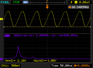
The oscillator operates around 10.14 Mhz, and I couldn’t really see any detail of the waveform with my old scope: it just didn’t have the necessary bandwidth. But with the new scope, the situation is quite a bit different. I powered the oscillator up with a pair of D cell alkalines. I adjusted the bias potentiometer for the best looking sine wave, and it’s not too bad. Here’s a screendump of its best looking sine wave, and the FFT of that signal below. You can see that there is a bit of a second harmonic (due mostly to the asymmetrical waveform) but that it’s overall pretty good. The peak to peak voltage is around 2.18 volts, which is about a 12 mw.
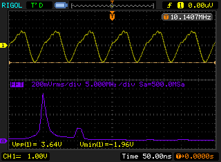
By adjusting the bias potentiometer, you can get more power out: the peak to peak voltage rises to around 3.64V, for an output of around 33mw. But the waveform looks much less uniform, more energy scattered into the second harmonic.
I’m really liking this. I will probably make some additional changes to this circuit tomorrow, but having a good scope to examine how the changes affect the performance is really awesome. A great investment in my electronic education.
I’ve been trying to do a bit more Arduino programming and interfacing lately. Nothing too difficult, but just trying to expand my junkbox and my skills so that I can quickly prototype new ideas and expand the kind of projects that I can tackle in the limited time that I seem to have for playing around.
I have written programs to use an Arduino to blink or beep Morse code before, but the programs were meant to control beacons, where they might just send the same message over and over, which I just compiled into the program. Today’s experiment did two things: it reads and buffers keystrokes from an old IBM PS/2 keyboard which I rescued from exile in my garage, and it actually keys my ham radio transmitter (a Yaesu FT-817ND) using a 4N31 optoisolator.
Most keyboards that you get today are interfaced via the Universal Serial Bus (USB). That’s kind of cool, but it’s also a bit of a travesty, since they require a lot more code (and a lot more knowledge) to interface what is ultimately a pretty simple device. Back in the old IBM AT days, keyboards were equipped with a large 5 pin DIN connector, and would transmit “scan codes” represent each character along a simple serial bus. The IBM PS/2 shrunk the connector to a six pin mini-DIN connector, but retained almost all the other features.
But if you want to do a tidy job, you’ll need some extra bits and pieces to hook them to your Arduino. Luckily, Sparkfun has a couple of cheap bits that will make it easy. I ordered some 6 pin MiniDIN connectors from them, along with a tiny $0.95 breakout board which you can tack together along with some header pins to make a little breadboard friendly connector. You need four connections: 5V, ground, and a clock and data line, which I connected to pins 3 and 4 on my Arduino.
You’ll also need a library. Yes, you could roll your own, but that would have added hours to this simple project. Instead, I chose this one, more or less at random from a number of possibilities. It seemed to work fine, and compiled properly even with my Arduino 1.0 setup. The code actually comes from the guys who make the Teensy, but the code works fine on regular Arduinos.
Then, I wrote the code. I wanted the user to be able to type ahead of the sending, so I needed to implement a ring buffer to store chars (currently up to 128) which I coded up from scratch in the simplest way possible. The way I used to do Morse sending was to set the output pin to be HIGH, then delay(), then set it to LOW. But we want to process new keystrokes and add them to the buffer as soon as you can. So, I implemented my own “delay” function, which loops to find new characters and inserts them in the buffer while waiting for the timeout. This seems to work pretty well.
Without further explanation, here’s the code:
[sourcecode lang=”cpp”]
#include <PS2Keyboard.h>
// _____ _ _ _ _ __ __
// |_ _| |_ ___ /_\ _ _ __| |_ _(_)_ _ ___ | \/ |___ _ _ ___ ___
// | | | ‘ \/ -_) / _ \| ‘_/ _` | || | | ‘ \/ _ \ | |\/| / _ \ ‘_(_-</ -_)
// |_| |_||_\___| /_/ \_\_| \__,_|\_,_|_|_||_\___/ |_| |_\___/_| /__/\___|
//
// _ __
// | |/ /___ _ _ ___ _ _
// | ‘ </ -_) || / -_) ‘_|
// |_|\_\___|\_, \___|_|
// |__/
//
// Version for the PS2 Keyboard
// using the library from http://www.pjrc.com/teensy/td_libs_PS2Keyboard.html
//
// Written by Mark VandeWettering K6HX
//
// This is just a quick Morse keyer program.
//
////////////////////////////////////////////////////////////////////////
//
// Here is a queue to store the characters that I’ve typed.
// To simplify the code, it can store a maximum of QUEUESIZE-1 characters
// before it fills up. What is a byte wasted between friends?
//
////////////////////////////////////////////////////////////////////////
char ltab[] = {
0b101, // A
0b11000, // B
0b11010, // C
0b1100, // D
0b10, // E
0b10010, // F
0b1110, // G
0b10000, // H
0b100, // I
0b10111, // J
0b1101, // K
0b10100, // L
0b111, // M
0b110, // N
0b1111, // O
0b10110, // P
0b11101, // Q
0b1010, // R
0b1000, // S
0b11, // T
0b1001, // U
0b10001, // V
0b1011, // W
0b11001, // X
0b11011, // Y
0b11100 // Z
} ;
if (!queueempty())
send(queuepop()) ;
}
[/sourcecode]
To key the transmitter, I used a 4N31 optoisolator. This code uses pin 13 to key the transmitter, so I wired it to pin 1 on the optoisolator, passing through a 1K current limiting resistor, and pin 2 ground. Pins 4 and 5 are wired to the tip and shield of a 3.5mm socket, which I then connected to the FT-817 key input using a 3.5mm stereo cable I had lying around. I could have used a little NPN transistor to do the keying, but the optoisolator keeps any current from the radio from circulating in the Arduino (and vice versa) which is a nice little insurance that nothing will zap either my radio or my microcontroller.
Here’s the resulting project:
Feel free to drop me a line if you find this code to be useful. Let me know how you adapted it to do something cool in your shack or lab.
Addendum: Friends Atdiy and Whisker of the tymkrs empire made a similar project a while ago, except that they used a board based upon a Propeller board, which does a lot of what my project does as well. If you like the Propeller instead (and if you’ve been following my blog and reading about WA0UWH’s beacon, why wouldn’t you?) you might check out their video:
January 21, 2012 | electronics | By: Mark VandeWettering
I was tinkering with a small electronics project (article and video to come) and needed a sound output. Digging around in my junkbox, I found one of these piezo speakers, and decided to use it, driving it with a square wave from my Arduino:
My initial test was supposed to be 700 Hz, but it sounded very high. I recorded a sample with Audacity and looked at the spectrum, and sure enough, it’s principle frequency was at 2100Hz. I then looked at the driving signal using my Rigol DS1102E (did I mention I got a new scope this week?) and sure enough, it was a nice 700 Hz square wave. Apparently the specifications on this little piezo element weren’t kidding: it has almost no frequency response below 1500Hz, so all you end up hearing are the third harmonic. The fifth harmonic is actually pretty weak too, so you end up with a pretty even sine wave, just at the wrong frequency.
I guess if I want higher quality sound out of this thing, I’ll need to rig a real speaker.
I share an interest in old computing technology with several of my friends and readers. An interesting sub-topic within this vast area is the world of computers based upon relays. In the last couple of days, I found cool links to two different relay based computing projects, so I thought I’d pass them along.
First is Jon Stanley’s Relay Computer Two. Consisting of 281 relays, it boasts an 8 bit data bus and a 16 bit address bus. His website gives the kind of dense, technical information that I like to see from a project like this. You’ll see how he implements adders (using Konrad Zuse’s design which constructs a one bit full adder out of two 4PDT relays). Very neat. Lots of cool details. It clanks along at less than 30 cycles per second. Yes, it uses solid state memory (as almost all amateur reconstructions do, it’s simply to expensive to do otherwise) but the result in a clicky, clanky marvel. Check it out (and make special note of the enormous capacitor in the power supply):
Then there is Rory’s awesome series of relay based computers, culminating in the TIM-8. There are all sorts of awesome laudable features in this build. He didn’t want to “cheat” and use solid state memory, so he struggled to find solutions. He ends up storing programs on paper receipt tape as a series of black and white lines which provide control signals to the rest of the computer. These are then loaded onto a motor driven spindle and read by a series of phototransistors (I think, not clear). The tape is rewound and replayed during program execution. Very cool. He also constructed his own solid state memory out of capacitors, with a density of about 9 bits per cubic inch. Very, very cool. Here’s one of his videos, but search around on his site, he has more:
This is just a plug for a cute little pair of gadgets that I got the other day.. If you are like me and use solderless breadboards to experiment with stuff on the Arduino, you end up with the Arduino and the breadboard connected by a hodge podge of wires, and if you accidently tug on a power supply cord or the USB cord, half connections come undone. Or, you do all this experimenting on the dining room table, and when you have to clear it away for dinner, all sorts of wires become undone. Frustrating. Even annoying.
So, I took out an insurance policy against annoyance and frustration and ordered a protyping board for the Arduino Uno from TAUTIC.com. TAUTIC Electronics LLC is one of those cool little bootstrapped companies that have chosen to embrace the Open Source Hardware ideas and offer products of interest to tinkerers like myself. This prototype board is basically just a solderless breadboard bonded to a blue plastic backer, with the holes properly drilled to attach an Arduino Uno and the necessary hardware. He also makes version for the chipKit microcontrollers manufactured by Diligent.
While I placed that order, I decided to also give one of his dual output breadboard power supplies a try. For $9, you get a nice little board that plugs into a prototype board and provides 5V on the top rail, and 3.3V on the bottom rail. Very spiffy. The boards were shipped to me literally on the day I ordered them, great customer service. Jayson has a number of other cool boards, including some thermocouple boards and a PIC based development board. Check his store out and see if there is something that catches your eye.
January 14, 2012 | Rants and Raves | By: Mark VandeWettering
We’ve all heard it (and most of us have said it): “X is just a dumbed down for the masses.” Heck, I came dangerously close to saying it myself in today’s earlier rant. But I didn’t say it, and I try not to, because I think it’s not really very useful.
First of all, if you really are a beginner, you probably need things to be dumbed down, at least a little. For instance, as a relative beginner working to self-educate himself in the field of electronics and RF design, I learned that diodes pass current in one direction, but not the other. This is a “dumbed down” version of diodes: they actually have a forward voltage drop, and it’s only when that forward voltage drop is exceeded that current passes. But that too is a dumbed down version of what diodes do. The forward drop isn’t constant, it depends on things like temperature. Also, there is actually a curve that relates voltage and current, they don’t just snap on. But that too is just a “dumbed down” version of what a diode is. And so on, and so on.
The fact is, these “dumbed down” versions of the diode are very useful: they do convey some bit of useful information and begin to give us some experience and intuition about reasoning about circuits that contain diodes. The only thing that is bad is if we envision that our “dumb” understanding of diodes was a complete understanding of diodes. Then, there would be circuits and behaviors that we simply couldn’t understand, because the real diodes are a bit more subtle than our dumb version, whatever level of understanding that might actually be.
But more than that, when we say something is dumbed down, we stray dangerously close (and often well beyond) calling the people who may use these simplified models as “dumb”. That simply isn’t productive, and runs counter to what I view as the purpose (and mostly successful achievement) of getting people interested in computing and electronics. The Arduino is successful because it does “dumb down” things enough for the people to experience success, who might otherwise have been frustrated and annoyed. When I hear people say that the Arduino is “dumbed down”, I really hear them telling people who use them (or even more tragically, might have used them) that they are stupid. I don’t want to call people stupid, especially those who might actually try something that I enjoy, and inspire me to do better work.
The problem I was trying to make clear was not that the Arduino was “dumbed down”, but that the default development environment was a path that eventually kind of dead ends: to gain any real expertise and fully use the power underlying the $2.50 piece of silicon at it’s heart, you almost need to start over: perhaps by using assembler as some has suggested, or perhaps just by using avr-gcc with avr-libc. You have to learn about interrupt vectors, and the hardware resources, because the particular abstractions that the default development enviroment present rob the underyling hardware of its power. To give another example, no less a luminary than Edsger Dykstra scolded a generation of computer science instructors and students that the BASIC programming language was a fatal disease from which they would never recover. It wasn’t true. For many, it was the only programming that they ever learned, but that wasn’t a bad thing. For many in my generation though, it was a stepping stone to an exciting and profitable career.
Don’t bother saying something is “dumbed down”. It’s pointless. Your understanding of almost anything worth knowing is almost certainly “dumbed down” from its reality. Revel in complexity. Don’t be ashamed that you don’t understand everything today: you won’t understand everything tomorrow either, but with luck, you might understand more than you do today.
Now, if I could develop a slightly less dumbed down idea of how FETs work, I could perhaps understand the behavior of my QRSS beacon a bit better. So that’s what I’ll work on for the rest of the evening…
First of all, I really like the Arduino. There are lots of reasons: great community, relatively inexpensive, wide hardware availability and variety, and often a good “impedance” match to projects. But there are a few design choices (both hardware and software) that can be a nuisance, especially as you try to push the limits of what can be done on such inexpensive and low power hardware.
First of all, there is the basic software philosophy. I love the fact that it is a single download: this simplifies installation, and whether you are an expert or a novice doesn’t matter, that’s simply more convenient. But using the program editor provided is simply not that desirable for experts who might be more used to Eclipse, or to an old fashioned kind of guy like myself for whom vi and Makefiles is more reasonable. With a little work you can find out where avr-gcc, avr-libc and avrdude are installed and add them to your search path, but you still have some work to build a Makefile which can compile your sketch from the command line. That’s a little annoying.
But more annoying are the design choices of the libraries themselves.
High among them are the heavy use of delay and the relative invisibility of interrupts. This may simplify short programs, but it provides no help to more sophisticated programs, and may in fact hinder them. Consider my experiments of last night (which fueled the rant of this morning). I merely wanted to implement a serial terminal using the TVout library and some serial communications library. The idea would be “read from serial, print to TVout”, voila, should be simple.
TVout generates NTSC video on the fly, and it basically works great. To do so, it uses regular timer interrupts. and if you dig into the library itself, you might find out that it uses Timer1. At regular interval, the timer 1 counter overflows, and the library knows that it’s time to bitbang out the video using some carefully constructed code. It also appears to use Timer2 to generate audio tones. Hmmm. The AVR chip that underlies the normal Arduino has only three timers… is that going to be a problem? How can I tell if another library also uses those timers?
You won’t find it in the documentation to any library. Arduino programming is supposed to be easy, and remove the need to understand how the underlying hardware works. Except that when you try to use two libraries together, and they happen to both use the same underlying timer resources, it doesn’t work right. There are no compile issues, it’s just one or both of the modules fail.
Which it did of course last night. You’d think that a loop like:
might have a chance of working, but it doesn’t. It drops and mangles characters horribly. While you might be able to poll some switches, apparently typing is something that is simply beyond the realm of expectation.
Some of you are probably going to leap to TVout’s defense, claiming that “You’re not doing it right! There is an example sketch which shows you the right way to do Serial and TVout!” Let’s have a look at that little sketch, shall we?
void loop() {
if (pserial.available()) {
TV.print((char)pserial.read());
}
}
[/sourcecode]
Okay, we have some new library, which we never heard of before. It’s apparently part of the TVout download. Documentation? No. It calls a function I haven’t seen before, “set_hbi_hook”. Is that documented? No. I am pretty sure it’s a hook which will get called at the end (or the beginning?) of a horizontal blanking interrupt (this isn’t my first rodeo) but what’s really going on here. The pserial.begin call must return a function… time to crack open the source code.
And, it’s about what you expect. There is a hook function that gets called on every line, right before the line is rendered. My guess is that it’s bad if the timing of the hook function is in anyway indeterminate, because then the rows will start at odd intervals. But each render routine starts with a line which waits… for some length…. maybe there is some amount of time (undocumented, different for PAL/NTSC, maybe just the front part of each scanline, read more code) that if you don’t exceed, you’ll be fine. What does pollserial do? Well, it snoops at the serial data registers (polling!) to see if a new character has arrived. It then puts it in a ringbuffer, so that it can be made available to the read call later. Okay, I understand.
But did I mention the reason I didn’t use this code in the first place? It’s that pollserial didn’t compile on my Arduino 1.0 setup (most libraries that aren’t part of the core don’t out of the box yet, in my experience). I could probably figure that out (has something to do with inheriting from the Print class and a prototype mismatch) but in my real, ultimate application, I wanted to read from a PS/2 keyboard. It will of course have the same (but differing in details) issues, and I’ll have to tweak their driver code to make it work with TVout too. Sigh.
Ultimately, I guess I disagree with one part of the Arduino philosophy: that programming can ever really be simple. Writing a program to blink an led, or read a switch isn’t hard, no matter what language or processor you use. Simple programs are simple, but the virtue of computers is that they can do things which are complex. If your software environment doesn’t give you sufficient help in organizing and doing complex actions, then you are missing out a great deal of the purpose of computers.
Addendum: While trying to fix the compile errors in pollserial, I found this fragment:
[sourcecode lang=”cpp”]
int pollserial::read() {
if (rxbuffer.head == rxbuffer.tail)
return -1;
else {
uint8_t c = rxbuffer.buffer[rxbuffer.tail];
//tail = (tail + 1) & 63;
if (rxbuffer.tail == BUFFER_SIZE)
rxbuffer.tail = 0;
else
rxbuffer.tail++;
return c;
}
}
[/sourcecode]
Can you spot the problem? Hints: BUFFER_SIZE is defined to 64, and rxbuffer.buffer is malloced to be BUFFER_SIZE bytes long.
Update: Welcome Hack-a-day readers! If you are looking for the schematics for this “transmitter” (really just a simple oscillator, send some love to radio guru Steve Weber over at his website. You could really use any oscillator you like, even a canned oscillator (although the square waves would generate lots of harmonics).
Yesterday’s project coupled a simple Colpitt’s oscillator (snipped from Steve Weber, KD1JV) with an Arduino. Steve used it to send temperature telemetry in Morse code back to his shack from an outdoor thermometer. But I thought that something else could be done: sending telemetry in Hellschreiber.
Hellschreiber is an early type of facsimile teleprinter system developed in the 1920s, which has enjoyed a certain amount of popularity in the amateur radio community. It sends characters using a conventional on-off keyed transmitter, just like Morse, but instead of sending dots and dashes of different lengths, it scans characters left to right, and top to bottom, and keys the transmitter on where each letter is “on”. Thus, a Morse transmitter can be modified pretty simply to send Hellschreiber.
So I did.
Here are some details. Hellschreiber is normally defined as sending characters defined on a 7×7 matrix, at 122.5 dots (2.5 characters) per second. But the actual font is actually defined on a 7×14 matrix. To keep the bandwidth of the signal down, the font doesn’t ever define a character that requires turning single dots on or off: the minimum signal changes are two dots long. These “half dots” are sent at 245 baud, or about 4.08ms per dot. Because I needed to account for the time spent looking up the character, I tuned that down to about 4.045ms. I was concerned that because I was keying the oscillator on and off, the startup time (which I estimated at about 2ms) could be a problem, but I suspect the shutdown time is about 2ms as well, so the overall system works better than you might imagine. The startup and shutdown keying waveforms are a bit erratic though, and the bandwidth of the signal is probably too wide. I think a better way to do this would be to build an oscillator that runs continuously, and then key a buffer amp with a filtered pulse to keep the bandwidth low. But for a 500 microwatt transmitter (estimated, and represents power going into the antenna, not radiated) it probably works just fine.
void
encodechar(int ch)
{
int i, x, y, fch ;
word fbits ;
/* It looks sloppy to continue searching even after you’ve
* found the letter you are looking for, but it makes the
* timing more deterministic, which will make tuning the
* exact timing a bit simpler.
*/
for (i=0; i<NGLYPHS; i++) {
fch = pgm_read_byte(&glyphtab[i].ch) ;
if (fch == ch) {
for (x=0; x<7; x++) {
fbits = pgm_read_word(&(glyphtab[i].col[x])) ;
for (y=0; y<14; y++) {
if (fbits & (1<<y))
digitalWrite(radioPin, HIGH) ;
else
digitalWrite(radioPin, LOW) ;
January 11, 2012 | Amateur Radio | By: Mark VandeWettering
Before toddling off to bed last night, I did a bit more tinkering, and a bit of thinking, and then a bit of research.
The YouTube video I made showed that the spurious radiation from just attaching a clip lead from the oscillator to my oscilloscope gave enough signal to inject itself into my RFSpace SDRIQ software defined radio, even without any antenna attached. I hypothesized the signal should be stronger with my regular 40M dipole antenna, so I tested that, and sure enough, my FT-817 attached to the 40m dipole easily is S7, even without doing any antenna tuning. This suggests that for any application on my small property, I could reduce the power significantly (and use little/no antenna) and still have very legible signals.
I used a 3.68Mhz crystal because I have something like 200 of them (I bought them for something like $3 for a big bag) but that’s kind of a ham unfriendly frequency. While it’s not very likely for such a weak signal to propagate significantly at the power levels we are talking about, but it’s perhaps possible that someone within a radius of a mile or so might be able to hear it, and be annoyed. Steve Weber used 4Mhz crystals, which are at the edge of the 80m band, and probably less well trafficked. A good, friendly idea.
Last, I was trying to understand what the regulations actually say about legal Part 15 operation. The regulations allow for experimenters to build five transmitters of this type for experimentation. On the 80m, you are suppose to keep the average field strength at just 15 microvolts per meter at a distance of 30m. Working through the approximations presented in Understanding the FCC Regulations for Low-Power, Non-Licensed Transmitters, this suggests that the product of power and antenna gain should be less than 6.6E-8 or so. While I know the input power, I don’t know how to measure (or estimate) either the output power or the antenna gain. Can anyone point me at a reference which shows how I might calculate the properties of a small 6″ long stub antenna at 4Mhz or so? I know it’s mostly an academic exercise, but it’d be nice to know the rough limits are, and the FCC regulations for Part 15 do say that we are supposed to “employ good engineering practices in order to ensure compliance with Part 15 standards”.
One final thing: as you can see from the oscilloscope, the output is far from a clean sine wave. It’s not horrible, but I was able to detect it at 2x and 3x the carrier frequency. The obvious thing would be to design a filter to clean it up, but most filter designs assume a 50 ohm (or thereabouts) output load, which this clearly doesn’t have. Is that a problem?
My G0UPL QRSS beacon is working pretty well, but is only putting out about 40mw of power, when it probably should be putting out 100mw. I was pondering oscillators in general, and (as I do often) surf for information and inspiration. I found both on Steve “Melt Solder” Weber’s website, in the form of a ATtiny based Wireless Morse thermometer. It was just a cool little circuit, so I tossed it together on a corner of my breadboard.
Works pretty well! I simulated the circuit using LTSpice before I built it, and found that it takes about 2ms for the oscillator to stabilize after powering down. At 12 wpm, each dit lasts 100ms, so it’s pretty clear that you can do a reasonable job of sending morse at pretty much any speed that most humans can use. To test the oscillator, I hooked up a pair of new D cells which were measured at 3.42 volts, and the current draw was a miserly 0.461 milliamperes for a maximum input power of around 1.5mw. The Arduino can supply 20ma, so it’s pretty obvious that you can drive this oscillator directly from an output pin. So, I used the Morse code sketch that I wrote a couple of years ago and voila! Instant beacon.
Regarding the legality, without any antenna, the effective radiated power of this antenna is incredibly low. I haven’t done any analysis of the circuit to state categorically that it falls inside the restrictions of Part 15 wireless devices, but I’d be shocked if it didn’t.
January 10, 2012 | Amateur Radio | By: Mark VandeWettering
I’m beginning to correct some of my misunderstandings re: JFETs and for some reason, oscillators are beginning to become something that I think of as interesting, particularly at very low voltages. Without comment, and for future perusal, I just present this cool link, which shows oscillators which can run on very low voltages (just a few millivolts):
Here is a snapshot from my QRSS grabber earlier today. You might want to click it to see it full size:
I’m curious: what phenomenon is causing the strong line doubling of the signals near the bottom? Note: not all the signals demonstrate this phenomenon, and it’s relatively rare, and commonly just fades away. Also note that the signal at the top does not show this line doubling. I suspect all the signals which are line doubled are in New Mexico.
Bonus question: I keep seeing a small wiggle like the one around 10.139975 or so, starting on 10 minute boundaries and lasting for about one minute. Anybody have any idea who that is?
January 9, 2012 | Amateur Radio | By: Mark VandeWettering
I’ve recently begun to try to systematically (if somewhat erratically) equip my home office (it aspires to be a lab) with the necessary parts and tools that I need to assemble projects which interest me. The reason for this is simple: if you have the tools, material and space to do a project, you will much more likely do it than if you have to acquire all three specifically. If, for instance, you want to experiment with RF oscillators or amplifiers, if you have toroids, transistors, crystals, caps and resistors floating around, you can tack one together in just a few minutes. If you toss in some diodes, you can make some mixers. Maybe you want to have some ICs around, such as the LM386s. Toss in some speakers, jacks and the like, and voila: you are building radios.
When you are just starting, each additional part or tool that you “need” but don’t have is stumbling block: it halts your progress, and keeps you from the projects that you truly want to do. So, how do you get from where you are (presumably with nothing) and get to the point where you can build things than interest you?
Here are some simple, and somewhat obvious guidelines.
Take a long view. You might know someone who’s garage is stuffed full of cool stuff, and what you envision as highly complex and detailed projects just seem to flow effortlessly off his desk. As far as I know, nobody starts with such collections as they emerge from the womb, so at some point, they were where you are today. Don’t suffer any angst over your relative lack of equipment and expertise. Peter Norvig has an excellent essay on learning to program. People have the expectation (fueled by books with titles like Learn to Program in 21 Days) that programming is easy, and they should be able to become experts quickly. But research shows that it takes years to develop expertise. This is good: it means you can invest modestly in acquiring the tools and materials you need, gathering both simultaneously over time.
Invest in tools first, consumables second. Since we are taking a long view, it makes sense to invest in tools. After all, if it takes you ten years to acquire skills, chances are you are going to use those tools quite a bit. On the other hand, components and consumables will probably get used up in projects. Acquire them lazily, as you need them, or as you find them.
Consider economies of scale. Often ordering a dozen of a particular part is the same cost as just ordering two or three. As an extreme example: consider the lowly 2N3904 NPN transistor. If you buy these one at a time at Radio Shack, you’ll pay about $1.19 for one. Digikey will sell them for something like $.43 in quantity one, but are down to $.12 if you buy one hundred of them. If you go to companies like Tayda Electronics you can get them for just $0.01 a piece. Consider adding fairly bulk quantities of common components to stock your junk box.
Substitute for hard to find components. Most of the rehashed circuits that the ham radio magazines continue to republish seem to need air spaced variable capacitors, which are frankly getting harder and harder to get, and more expensive when you can. Keep an eye out for those components, but also consider making substitutions. Hans Summers made me aware of using LEDs and other diodes as varactors. Varactors are reasonably difficult to find, but LEDs are everywhere. If you dig around, you can find articles like this excellent one on how to design circuits around this idea.
Spend time researching and asking questions. It’s easy to spend money, it’s hard to save money. But if you spend some time doing research, you can often learn a lot, and therefore save a lot. DIg around. See what others have done. View everything through the lens of what skills and equipment you’d need to reproduce the same kind of projects that you see.
That’s the general background: in the next few days I’ll try to do a post of what items are making it into my junkbox. Stay tuned.
January 7, 2012 | Arduino | By: Mark VandeWettering
Allright, I was playing Skyrim most of the day, and didn’t really have my brain firing at it’s highest level when I sat down and decided to try to put something together. We’ve all been there, right? I realized that I had some of this cool RGB LED strip that I ordered from Tayda Electronics, and it was just lying there, mocking me. So, I embarked upon quite easily the simplest things that I have ever done: cross fading RGB LEDs. Going boldly where everyone has gone before: it’s my motto.
First of all, complete credit must go to Lady Ada and her terrific tutorial on this very subject. I shamelessly copied what she did, and it worked out great. So go there, and read everything she had to say. I’ll just add a few comments:
The RGB strip cuts very easy, and strips pretty easy too. Be careful to use good ventilation when soldering leads onto this stuff though, as the plastic/rubbery stuff residue doesn’t smell very nice when heat is applied.
I went ahead and ordered the STP16NF06 MOSFETs that she recommended when I placed my last Digikey order. Price was about $.85 each, which is quite reasonable.
Tayda’s RGB strip seems like a very good deal, and you could easily use this trip for a wide variety of craft, art, or electronics projects.
To experiment, I cut off four segments (a little under a foot) and soldered on some leads, and wrapped them with electrical tape. Rather than swipe Lady Ada’s code, I quickly penned this up:
[sourcecode lang=”cpp”]
const int rPin = 3 ;
const int gPin = 5 ;
const int bPin = 6 ;
And it worked the first time! Here’s the YouTube video:
It’s really easy to get the electronics working, and the Arduino and it’s software environment make it so simple. Too simple. I’m sorry to have embarrassed you with this, but perhaps you’ve had a craft or art project that could use some LEDs kicking around in your head, but you haven’t been kicked into action. Perhaps the easiness of this will inspire. If so, my work is done!
I could of days ago, I blogged about WA0UWH’s Propeller Beacon. Over the last couple of days, I worked on fixing a few small issues with my old beacon code, and have an experimental QRSS grabber up and running on qrss.info. And, what’s totally cool is that I’m hearing Eldon’s QRSS beacon, just over 700 miles away. Check the screen grab:
Eldon’s signal is the slant-Morse signal just about 1/3 of the way down (right around 10.140050). His signal starts with a propeller, and then has a series of slanted lines. Forward slashes are read as dots, and backward slashes as dashes. You can work out WA0UWH (easier on the signal near the right edge), followed by the letters WA. Pretty neat!
Other callsigns are AE5XI, NM7J, KD5SSJ, KC5EVR (I think) and WV5N, read from top to bottom. Early in the morning (around 4:00AM my time) I also received W0TJ and the flying W of Bruce, W1BW, but as yet I haven’t heard anything from our VK or ZL brethren down under. I’ll keep the grabber up for the rest of the week, perhaps down only intermittently to tweak the software, and then I’ll shift to transmit over the weekend with my G0UPL beacon.
I’m Mark VandeWettering, former senior technical director for Pixar Animation Studios, and (for the moment I’m a husband and father and grandfather. I like telescope making, radio, and all sorts of other things.
Latest Comments
I recall burning three or four weeks of a sabbatical getting Saccade.com on the air with Wordpress. So much tweaking…
I move my pretty useless blog to Hugo about 7 years ago, since I got frustrated at too many security…
Something I used to good effect for a while was a "Pocketmod". You take a single page, fold it a…
Bloat is a serious problem, to be sure, but I'm not aware of many modern programming languages that avoid it.…
I'm running static pages (Notepad++) and a couple instances of Wordpress, and an instance of dokuwiki, all on ubuntu on…
")


I recall burning three or four weeks of a sabbatical getting Saccade.com on the air with Wordpress. So much tweaking…