December 19, 2018 | My Projects | By: Mark VandeWettering
I’ve been interested in low power beacon transmitters for a long time. If you’ve followed my blog, you’ve probably read about my experiments with WSPR and QRSS operation. Most of those took place on 30m using my FT817 transmitter, sometimes with software that I wrote myself. But I’ve long thought that I should homebrew a transmitter, and the idea of making it solar powered has always been in the back of my mind.
These operations have all been on ham frequencies, but even if you are unlicensed in the United States, you can get experiment with low power beacon operation under what is known as “Part 15“. These rules are part of the Code of Federal Regulations, Title 47, and specify certain bands and limitations as suitable for unlicensed devices. Rather than reading the boring regulations, you can go to Long Wave Club of America website and read up on experimentation under Part 15. You’ll generally find operation divided into “LowFER” (operation below 200khz, usually in the 2200m and 1750m bands), “MedFER” (operation in the AM broadcast band, usually between 1600khz and 1800khz) and “HiFER” (mostly centered around 13.55Mhz).
I was initially most interested in the LowFER bands, but I’ve never really gotten off the ground with the project, but recently have become more interested in operation in the HiFER bands. It presents some significant limitations. The most desirable band is limited between 13.553 and 13.567 Mhz. The total power output is specified in terms of a field strength at 30m distance from the antenna, but is on the order of one milliwatt into a half wave dipole at the frequency. You also are supposed to maintain frequency stablity to about +/- 0.01% over a temperature range of -20 to 50 degrees C.
This isn’t a lot of power, so it can be challenging to get an effective signal out, but it also makes for some interesting opportunities for home brew construction. Most beacons of this sort are small crystal controlled transmitters, and they can be powered by reasonably small solar cells, and controlled by inexpensive, low power, eight bit microcontrollers that are readily available.
Dave Richards (AA7EE) wrote up an awesome description of his Boris Hifer beacon, named after his cat. It’s a very straightforward design: a Collpitt’s crystal oscillator, a small two stage low pass filter, and an ATtiny85 microcontroller driven by a LP2950 5V regulator that is powered directly from his solar panel. (He also points at this $20 kit from Chris Smolinksi at blackcatsystems that would be dead simple to put together). As it happens, I have almost all the parts in my junk drawer, and could easily put such a beacon together. I even have a stash of the 13.56 crystals somewhere.
Dave’s construction is gorgeous, and he mounted it fairly low at the top of a fence. I have a similar fence at the back of my property. I would be tempted to use a more sophisticated solar setup perhaps utilizing a small battery. Propagation on this frequency is probably better during the daylight hours, but the solar panel likely generates an excess of power each day, and being able to survive small dips in cloud cover and the like would be good. But then his experience is that even on cloudy days his beacon wakes up, so perhaps I’m overthinking it. He also has a good description of using the BOD (brown out detection) in the ATtiny85 to ensure proper startup in varying voltage conditions. His write-up is really great, and will no doubt save me from a lot of hair pulling.
Well worth reading. You might also read his page about making a temperature beacon which was inspired by K7TMG and also this short experiment I did back in 2012 (apologies for the jittery phone video):
December 18, 2018 | My Projects | By: Mark VandeWettering
As part of my attempt to become slightly more virtuous, I’ve been trying to do four hours of work cleaning and organizing my garage workshop every weekend. Last weekend, I got to the point where I was forced to address my cordless lawnmower.
My mower is a fairly old Black and Decker model CMM1000, which uses a 24V lead acid battery. I hadn’t used it in several years. I had bought a gas-powered Toro lawnmower because the B&D was occasionally underpowered, particularly when the lawn got tall. It was also a mulching lawnmower, and over the years a thick layer of thatch had formed in the lawn, and it didn’t really look very good. I tried shifting to use the side outlet to bag the clippings, but that never seemed to work very well either.
But in any case, I had thought the B&D should be in good working order: it certainly was when I had left it a few years ago. I plugged it in to recharge it, and… well, nothing good happened. 12 hours later and the mower still wouldn’t start. It’s not shocking really: I had probably left the battery in a discharged state for a very long time, and it was probably dead.
Sunday I decided to try to extract the battery and put it on the bench, and see what I could figure out. Sadly, Black and Decker doesn’t seem to have the manual for this mower on their website any longers. Boo! A bit of Internet searching found lots of websites that would install various bits of crap on my machine or exchange a new account for a download of the manual, but all that was irritating. I decided to turn to YouTube to determine if someone had done this. And, of course they had.
This didn’t look too hard, so I dug out a Phillips screw driver, and my socket set, and started to work. Removing the throttle control and the two rear screws on the main housing wasn’t difficult. I then moved to the front screws, which lie in the bottom of a hole (maybe two inches deep) in the front housing. These holes were chock full of grass and dirt (naturally) but luckily I have an aircompressor and a blow gun, which made short work of the dirt. I blew them all out, and then took my handy Phillips to it.
Hmmm. No dice! I couldn’t get a grip on it. I changed bits to a smaller one. Still no dice. Finally, on a hunch I got a small flashlight so I could peer down into it. And… it was a Torx screwhead. Grumble!
Luckily, I have a pretty good supply of (very seldom used) Torx drivers, and a few minutes later I got the silly thing out. What was kind of annoying was that the video didn’t mention them being Torx screws, and the fact that the other two bolts on the same part were both Phillips. Grrr.
But it was pretty easy going from there. I took off the cover housing, and revealed the foam encasing the battery. Pulling the front piece did snap part of it off, but a little glue will restore it to good condition, and I got the battery out.
I say “battery” but it is in fact two 12V batteries mounted back to back and jumped in series to form one 24V pack. I got out my trusty multimeter, and found that the total voltage was around 12.5V for both cells, or about 6.5V each. I removed the strap that connected the two batteries so that I had them separated, and used my little 12V charger on one half. I also wired in a small LED voltmeter across them. It read about 11.2V.
Twelve hours later, it was about 11.3V. I took off the charger, and the voltage immediately sagged and the LED volt meter went out. Using my multimeter, it showed about 5v.
I proclaimed the batteries dead, and went inside to find out how much it would cost to replace them. Our local Batteries+Bulbs seemed like they stocked a Duracell Ultra replacement, but they were $80 for each, resulting in a replacement cost north of $150, which seemed like a lot. Amazon would ship me a pair of MightyMax batteries that would serve as a replacement for just $75. I’ve been using a Mighty Max as the power source for my solar energy project, and they seemed to work just fine. So, I placed my order and am awaiting the shipment.
So, while I’m waiting, I went back to thinking about Torx screws. I stripped one of the heads pretty well trying to motor it out with the Phillips, so I thought I should replace it. The question is should I replace it with Torx or Phillips?
See, while I grumble at Torx screws, I do basically admit to their fundamental superiority. Let’s face it, Phillips heads suck. They are actually designed to cam out as part of a crude form of torque limiting. This wouldn’t be bad if either the screws or the screw drivers you used were tough enough to handle this ill-treatment without mangling themselves. This is simply not the case with crappy zinc-pot-metal-lowest-bidder fasteners. They are really easy to mangle, and if you think that you might have to undo and redo them, it’s possible for you to end up with a bout of swearing. I hate regular hex key screws (such as seem prevalent in 3D printers) for much the same reason: in small sizes they simply are too easy to strip.
Torx screws are simply engineered better. They are designed not to cam out, and thus are much harder to strip. That alone means I should like them.
But I hate that the mower uses a mix of the two. So, the question of the day is: Should I replace all the screws I took out with Torx, replace them all with Phillips, or leave them with the odd mix that I found?
Feel free to leave your comments in, well, the comments.
December 10, 2018 | My Projects | By: Mark VandeWettering
It’s not uncommon for me to find unusual, nerdy objects while cleaning or organizing. I’m a bit of an eclectic pack rat, and have all sorts of weird objects, and some I literally have placed on shelves and forgotten about. Since I am trying to tidy up my garage work area, I’ve been finding objects wich I haven’t seen in quite a while, and I thought that I would share some of them with you. Perhaps this will become a new feature on my blog.
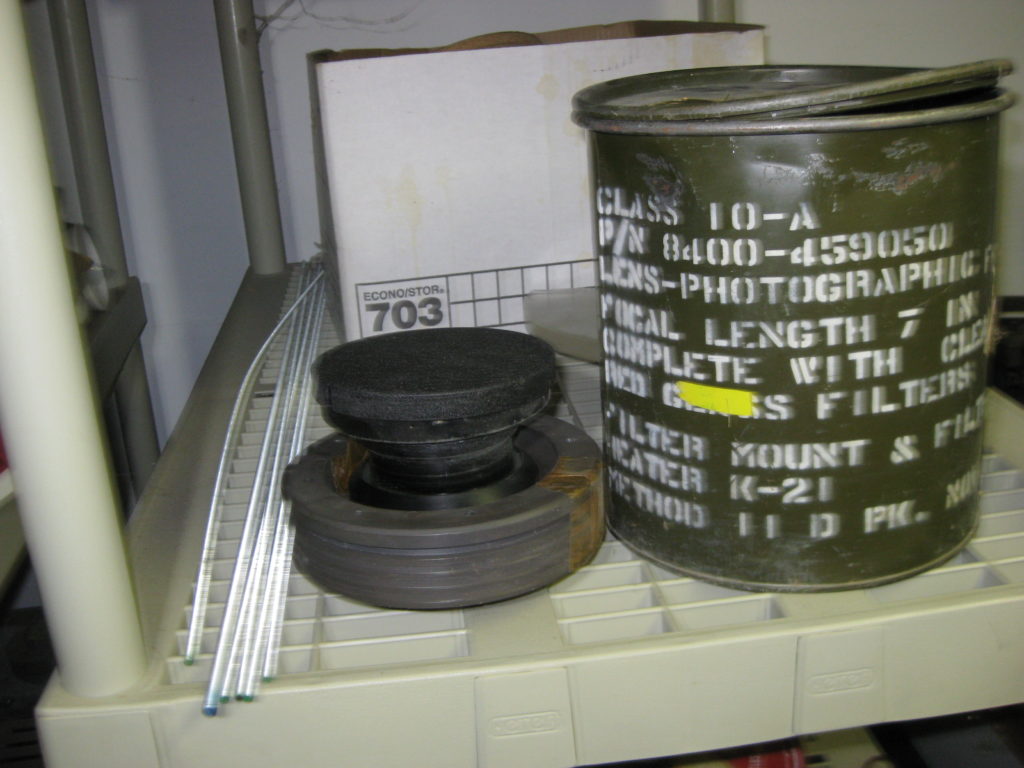
Today’s found item is a Kodak Aero-Ektar lens. I snapped a couple of quick pictures:
The lens itself, with lens cap on, with the accompanying khaki colored storage can.
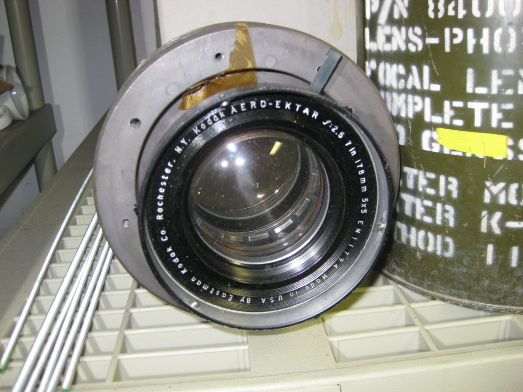
The lens itself, which is perhaps the most common sort, a 178mm f:2.5.
The Aero-Ektar was one of Kodak’s crown jewels in lens design, and was covered by a 1941 Patent by George Aklin, which gives a lot of details about its design.
Several versions of this lens were made, including a 12″ focal length. This one is the most common design, the 7″ focal length with a weight of around 3.2 pounds. It’s quite a chunky piece of glass. They were originally designed for aerial reconnaissance. I was trying to find a serial number on mine, but other than a few hand scratched numbers on the lens, was not able to find mine. I found Michael Briggs’ site which proved to be pretty interesting and informative. Most notably, it pointed to the fact that these lenses included the use of thoriated glass (glass that includes Thorium) and thus they are radioactive. Apparently it is common for such lenses to darken to a brownish color over time, and shining a bright light back through this lens does show that at least one of the inner elements shows the telltale faint brown color.
I guess I will be storing this in a can in the far side of the garage. I’m not especially concerned for all the reasons mentioned on Briggs’ site, but neither am I going to stash it underneath my pillow.
I don’t have any gear to actually measure any of the radiation coming from this gadget. If any of my hacker/geek friends do, and happen to be in the area please let me know: I’d love to have the lens measured.
I’ve no real plans for this. I offered it to a colleague who does a lot of interesting camera work, but (naturally) he already has one. They apparently bring a fairly good price on Ebay, so I could convert this one into additional monies for other projects. But it is an interesting artifact, and adapting it for a home made camera could be interesting, and would give a lot better images than my previous foamcore camera attempts. Anybody have any ideas? Any lens hackers interested in having this interesting bit of optical history?
Stay tuned for another episode of Found Item.
Addendum: I was an idiot, the serial number is right on the front: EM11794. The EM code means the lens was manufactured in 1943.
December 9, 2018 | My Projects | By: Mark VandeWettering
This weekend I mostly did work on further organization and cleaning of my garage workshop. This included taking out the old dog door and cutting a plywood cover to block it up, putting up a monitor mount so I could hang a new $80 22″ HDTV that I could use as a monitor, and then some general cleaning and organization of four shelving units.
But as I finished, I thought I would go back and try to understand the issue with my solar project. When I had taken it in from the outdoor location, it seemed to go off line, and no longer connected to the Adafruit IO service that I have been using. I suspected that I knew what the issue was, but today was first time that I could sit down and actually debug it.
The problem arises because of the haphazard way I cobbled together the code that runs on the ESP8266 module. It begins (in its Arduino setup() function) by probing for the existence of all of the I2C sensor modules that are installed. When I first coded this up, I wanted it to check just so I could be sure that the peripherals where installed and accessible via the bus. Thus, if it didn’t detect the peripheral, it printed a warning message and then entered a dead loop, where the watchdog timer would force a reset.
Of course, when the module is deployed in the garden, this isn’t especially useful. As I coded it, the check occurs even before the WiFi network is initialized, so no message gets sent. This also prevents the system from being able to be reflashed with an OTA update. Not a good state of affairs.
This was the state when I sat down at the workbench today. I could have simply hooked the ESP8266 module up via the USB to my laptop and worked on debugging it that way, but I had a new technique available, so I decided to use it. I had a second module programmed with the esp-link software (as I described in a previous posting) so I was able to monitor the boot messages.
What I discovered was that the MCP9808 temperature module was not being found by the I2C bus probe. To help with debugging, I decided to write some code that would try to probe all available I2C addresses, and print out a nice table of all the peripherals it found.
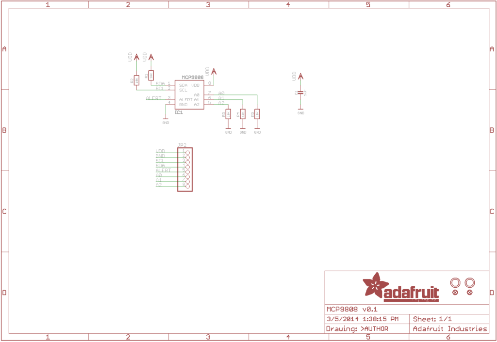
What it revealed was that the MCP9808 was actually being detected at address 0x19, whereas the default location was 0x18. The module does have three address pins to allow you to change its address, but according to the schematic, it has resistors in place that should pull the address low.
I’m was confused why it was acting as if A0 is pulled high, but I decided to just install a jumper to tie it to ground. And, boom! Booted right up and started to log data again for the first time in a week.
So, it’s working (after a fashion) but it does spawn a bunch of new tasks for me to work on for the next few days.
First, why did I need to tie the address pins explicitly low? Never seemed to have to do that before. It puzzles me, and I’d like to resolve it.
Rewrite the application. In fact, I’ve already begun on this. The biggest change is that it’s much more forgiving about the absence of peripherals that it expects to find. Notably, it connects to the WiFi network first, and only then does it start to probe the I2C network and take telemetry measurements. It’s also careful to ensure to process messages related to the Over The Air (OTA) updates, so that if I do need to update the software, it will be listening for the updates.
And while we are at it, I think it’s time to stop using Adafruit IO’s MQTT server. It’s a good, quick and easy way to get started, and allows you to setup a quick dashboard, but there are a number of problems that make it less than ideal. In particular, it doesn’t support retained messages properly, either in the client side or on the server. I have installed the mosquitto server, and will eventually move to that instead. I have decided to shift to the PubSubClient library which also appears to work with SSL and provides the retained message support that I like.
The current version is rather overactive: it records telemetry once a minute and pushes it to the servers. In between, it’s running, just busywait-ing in a loop, on the off chance that it receives a request to update its firmware. The new version should update telemetry at a longer interval, and use deepsleep to lower its power requirements in between.
The current version of the software is one-directional: it just sends telemetry to the broker. But MQTT is a bidirectional protocol, and it can receive information from the broker as well. I’ve tested this a bit, and envision it be able to send new configuration messages to the sensor.
In particular, we can use retained messages to set the “mode” of the sensor. When the sensor wakes up, it will receive a retained message from the broker indicating what mode it should be in. If it is in battery saving mode, it does a read of all its sensors, sends them to the broker and then goes to deep sleep to save energy. If the mode was “wait for update”, then it can enter a loop where it stays alive, waiting for a firmware update.
That’s about it for now. Stay tuned for more (and eventually code on github).
December 7, 2018 | My Projects | By: Mark VandeWettering
I’ve been interested in optics for many years, ever since I started building my own telescopes at age 11 and began writing ray-tracing software in my early twenties. But one thing that I haven’t experimented with too much is polarization, probably because my self-educated view of light is mostly in the form of little billiard balls called photons, and understanding polarization requires understanding quantum mechanics, and while I’m not completely ignorant of that stuff, I must admit it seems mostly baffling, and haven’t worked hard to figure it out since modeling polarization in computer graphics has been (mostly) of limited utility.
So, I found Jeri’s video pretty cool. She demonstrates a type of optical device that I’d never seen before, which is always cool. Check it out.
As a tiny bit of value added, I thought I’d add a video demonstrating a polarization effect shattered my early feeling that I understood what polarization worked: the three polarizer experiment. A little YouTube by minutephysics has a nice video demonstration of the effect and uses it to introduce Bell’s theorem:
December 6, 2018 | ESP8266 | By: Mark VandeWettering
I was hoping to be a little further on writing up and making video of my solar energy project, but a blown power steering pup in my Expedition left me stranded for a couple of hours on Tuesday night, and I’m still scrambling to get some of my intermediate goals up to date. But I did get some time to at least accomplish one of my goals for the week, and I thought I would share.
If you are “old school” like me (which is really just a nicer way to say “old”) you probably do a lot of your debugging with simple print statements. In the case of embedded systems, this are usually routed to a serial output, perhaps that is used only for that purpose. My solar satellite project is no exception: it spews a fair amount of informational data to its serial port as it goes about its business, mostly help me incrementally develop and test modules in the system.
But in the case of my solar project, I eventually want to deploy this system in a location where I won’t have any simple way to monitor the serial output. For a month, it sat on my patio, and being entirely powered by a small solar panel and battery setup, it didn’t seem like stringing a long serial cable out there was a good idea. I could of course rewrite the core of my system to include the ability to log serial data to a socket, and then listen for connections. But this adds a lot of complexity to my relatively simple application, and none of it is very interesting. I’ve also been thinking of experimenting with using other micro-controllers which may not have wireless capabilities of their own, and being able to debug (or reflash) those via wireless, and then perhaps removing the wireless logging once the system is working seemed valuable.
So, the solution would be to use a second separate wireless module that could monitor the controller’s serial port, and then do all the magic itself. And luckily, somebody has already done all the hard lifting, so there is already firmware out there to do it (and a lot more).
For my test, I dug a second WEMOS D1 Mini module out of my pile, and flashed it using the directions for the 32Mbit module. I then configured it to use station mode, attached it to my home network, and then did the bare minimum set of connections: connected 5V and GND from the first module to the same on the esp-link module, and then connected RX/TX to TX/RX. And booted the system.
Worked like a charm. I could either use telnet or nc to connect directly to port 23 on the module, and you’ll be able to interact with the serial port on the target board. It also hosts a small webpage with an embedded terminal module (much like the Arduino Monitor from the Arduino IDE). This enables you to (for instance) toggle the reset on the target board (which I didn’t connect, but which could be enormously useful).
I’ve barely scratched the surface of the functionality provided by this software. It can be used (for instance) to provide WiFi services to microcontrollers without any WiFi hardware of their own, at a very inexpensive price. And of course I could choose to remove the module once I’m done with the need for debugging. Very versatile.
December 3, 2018 | My Projects | By: Mark VandeWettering
Okay, I began this weekend with every intention of doing a video about my solar energy project. But in true usual “brainwagon” fashion, my attempt collapsed into a seemingly infinite regress of projects and subprojects, and the eventual goal of producing a video pushed beyond the horizon of the weekend. But still, I thought I’d owe you all an update anyway, and any documentation of motion toward my goal is likely to make me more enthused about my goal, so here is at least a run down of what I did.
But first, Dean put out his first video under the new #nerdthunder tag. He took several cheap solar garden lights and chained them together to create a higher voltage source, with the ultimate idea of powering some kind of motion sensor that can be used to alert him to the presence of birds who sometimes get caught inside his bird feeder.
Nifty, and somewhat parallel to my own project. I ultimately wanted to power my motion detecting hummingbird camera that I’ve talked about on this blog before, so I constructed a somewhat larger system. It consists of the following components:
The basic idea was to create a basic solar system with solar panel, dedicated charge controller, and a battery, and then instrument it with sensors to measure the voltage and current (and therefore, the power) that is generated by the solar panel and then used to charge the battery. I could then do things like log them to an MQTT server (I’ve been using the free service provided by Adafruit, graph them over time, and use them to measure the total power consumed by the system, and judge the overall efficiency.
And just learn.
And, it was working pretty well until the week before Thanksgiving. Then, I made a somewhat silly mistake: I added a little LED voltmeter across the battery terminals so that rather than being forced to go to the web, I could just glance out my window and see what the status of the battery was. The problem was that the voltmeter itself draws a bit of current (I haven’t checked how much yet) and it isn’t connected to the load, it was connected across the battery terminals directly. The charge controller has over discharge protection, which means that when the battery voltage drops below some minimum (the default is 10.7v) it disconnects the load from the battery so the battery doesn’t drop below that minimum voltage. It then waits until the battery charges above some voltage (I think 12.5V or so) before reconnected the load. I should have connected the LEDs across the load, so that they will disconnect. But since I connected them across the battery, it ran the battery really low when we had an extended bout of rain with appreciable solar charging. When I finally realized what had happened, I disassembled the setup and brought it to my workbench. Slapping my multimeter on it revealed a voltage of just 3.75V. Not good.
So, all that happened before the weekend. I had some ideas about how I would make a video describing the system. But first, a few issues…
My workbench wasn’t really setup for hacking in my garage. In particular, I had mostly used it for woodworking, which meant that it was on the other side of the garage, and not near any real electrical outlets. I had done some cleaning, but there still as a lot to do. I thought I’d go ahead and move the bench to the other side of the garage nearer some real power outlets, and that meant more cleaning. I was thinking of using my GoPro to record a time lapse of me working, but sadly discovered that the crash that took out my DJI Phantom 2 had also seemingly claimed the GoPro (it doesn’t appear to charge or power on). Instead, I snapped some pictures of some of the stuff that I uncovered while tidying. Not sure why some of the photos turned out so crushed color wise: I’ll have to fix it later today. Stay tuned.
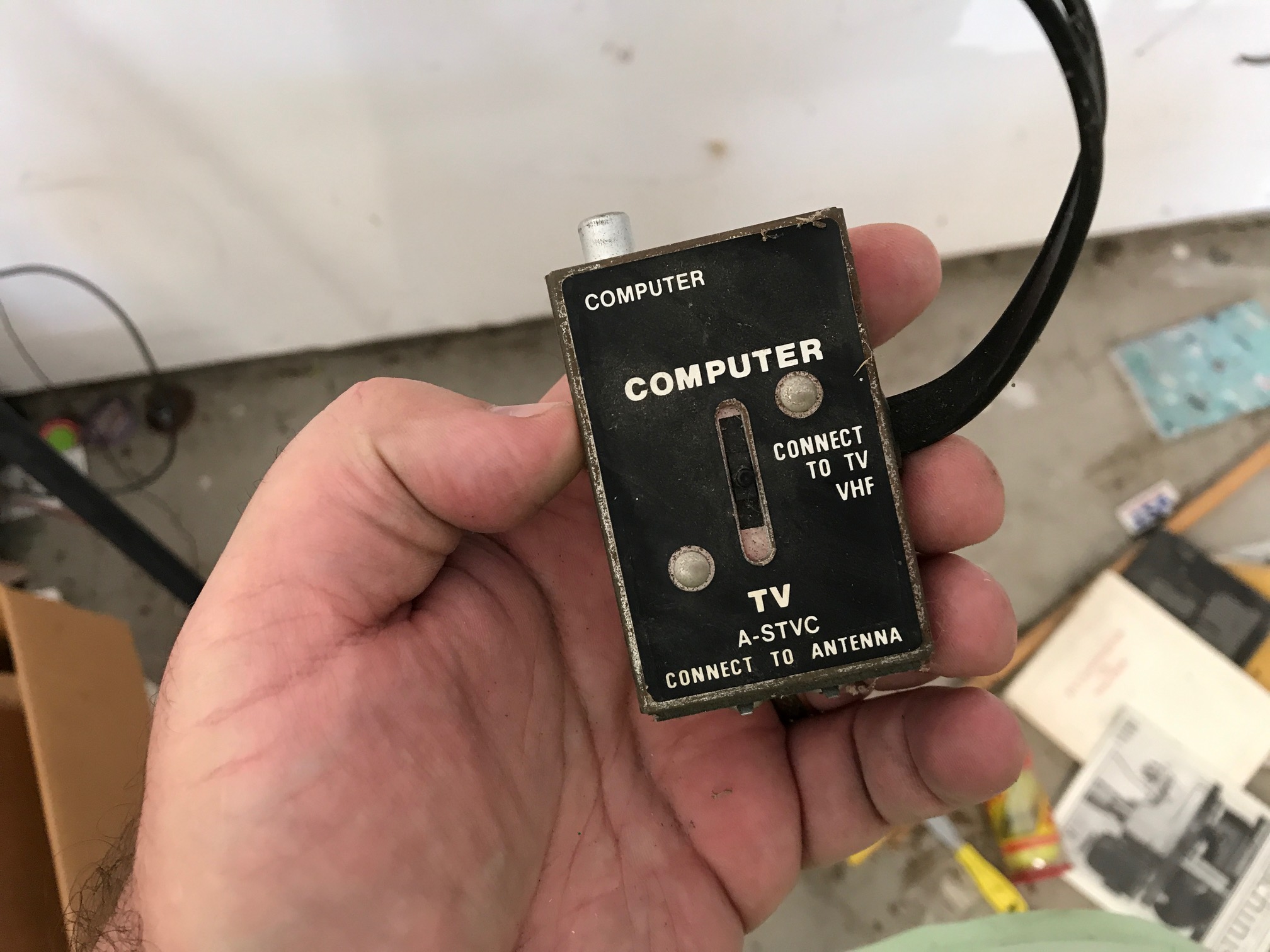
You have to be pretty old to remember these
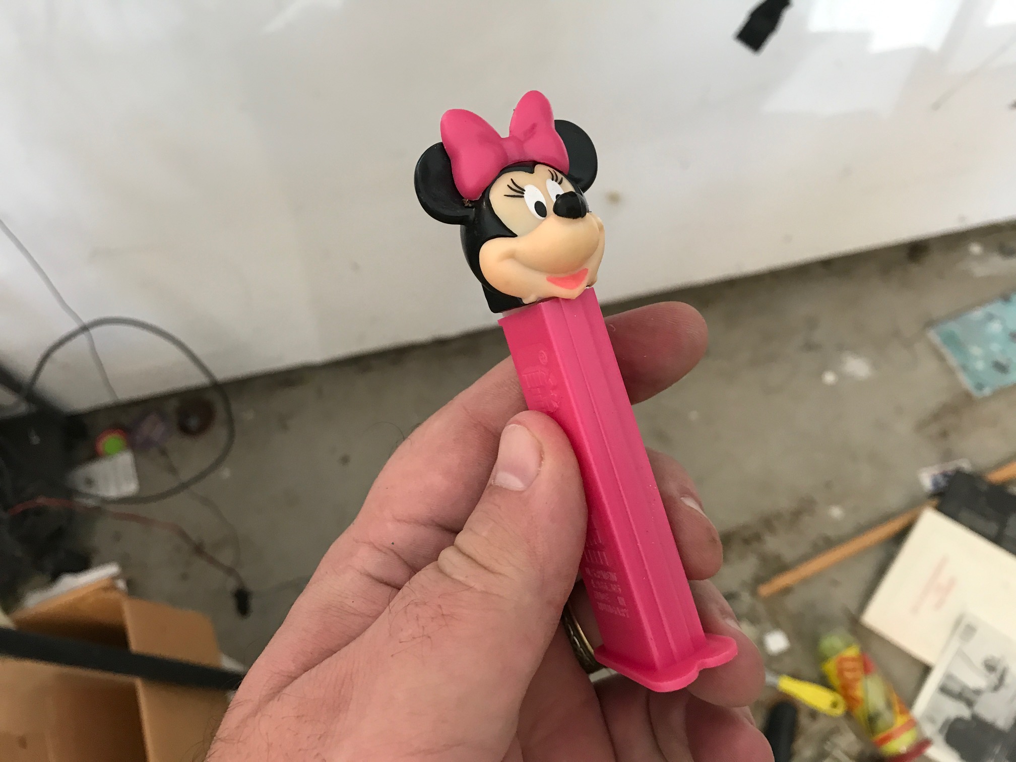
A Minnie Mouse Pez Dispenser
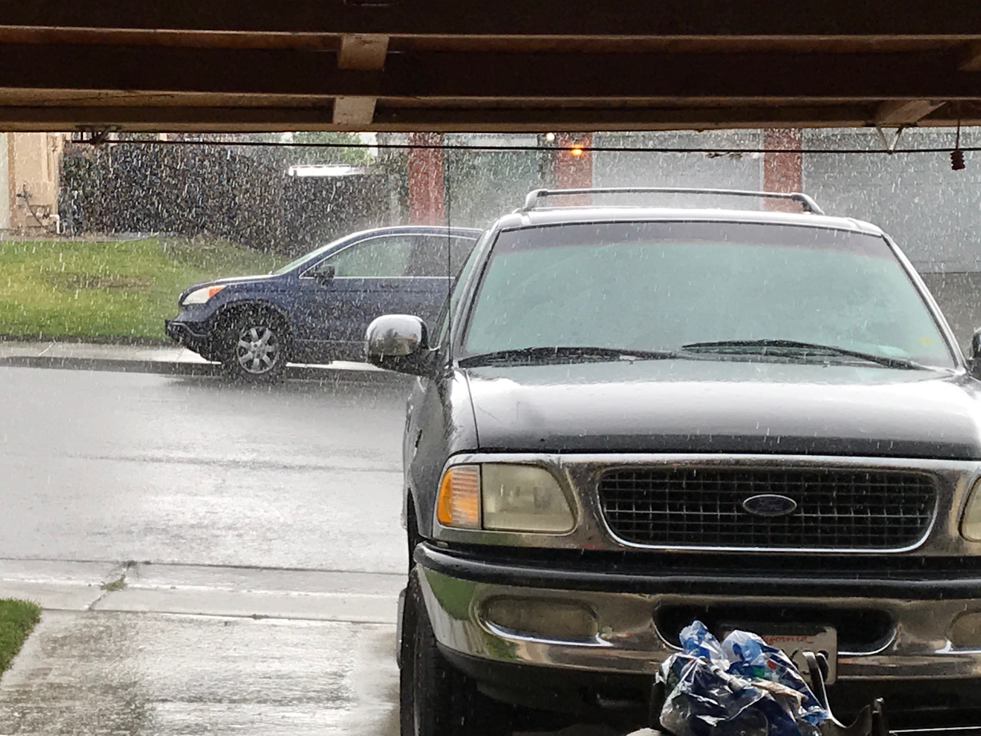
It was raining…
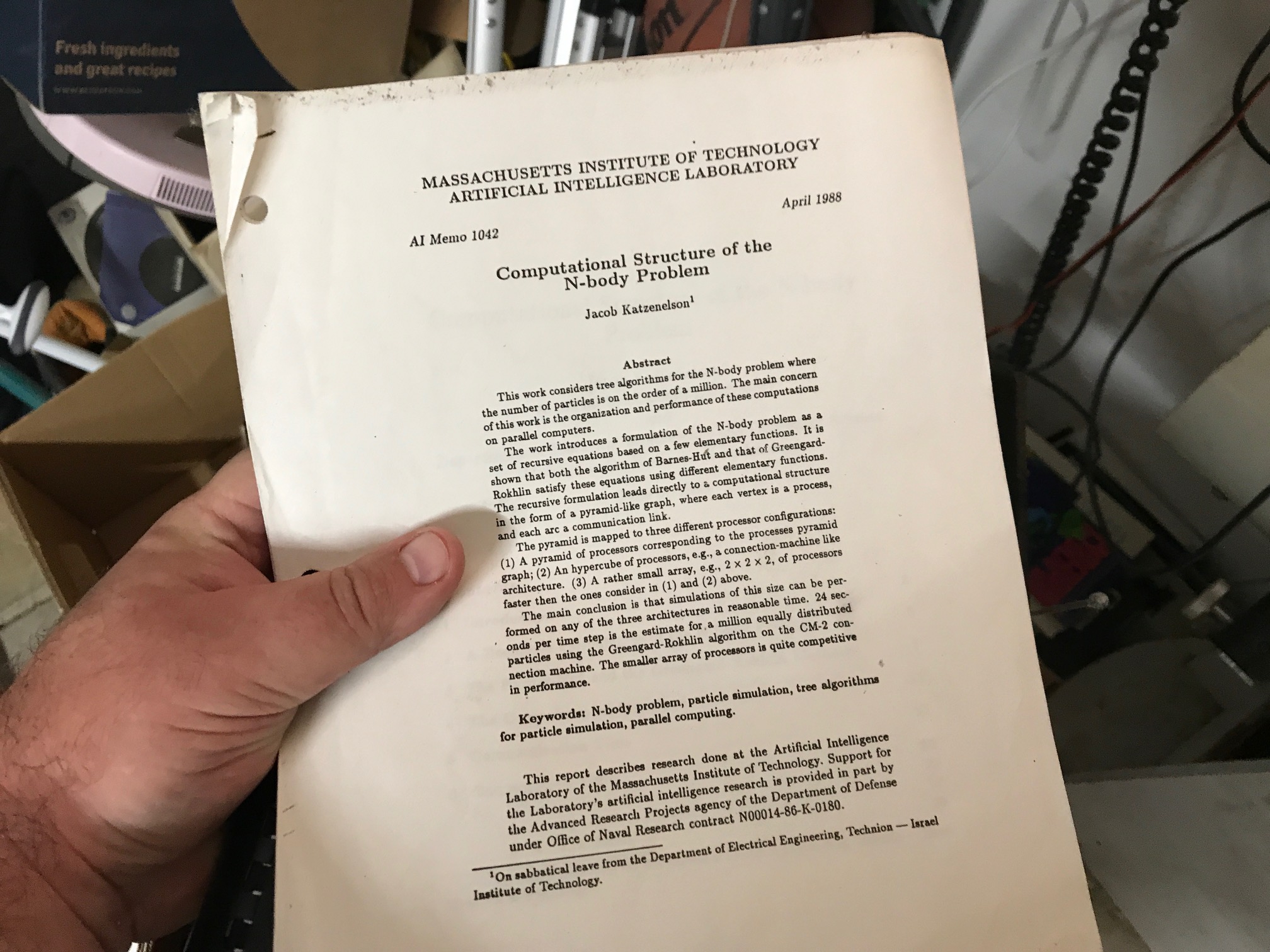
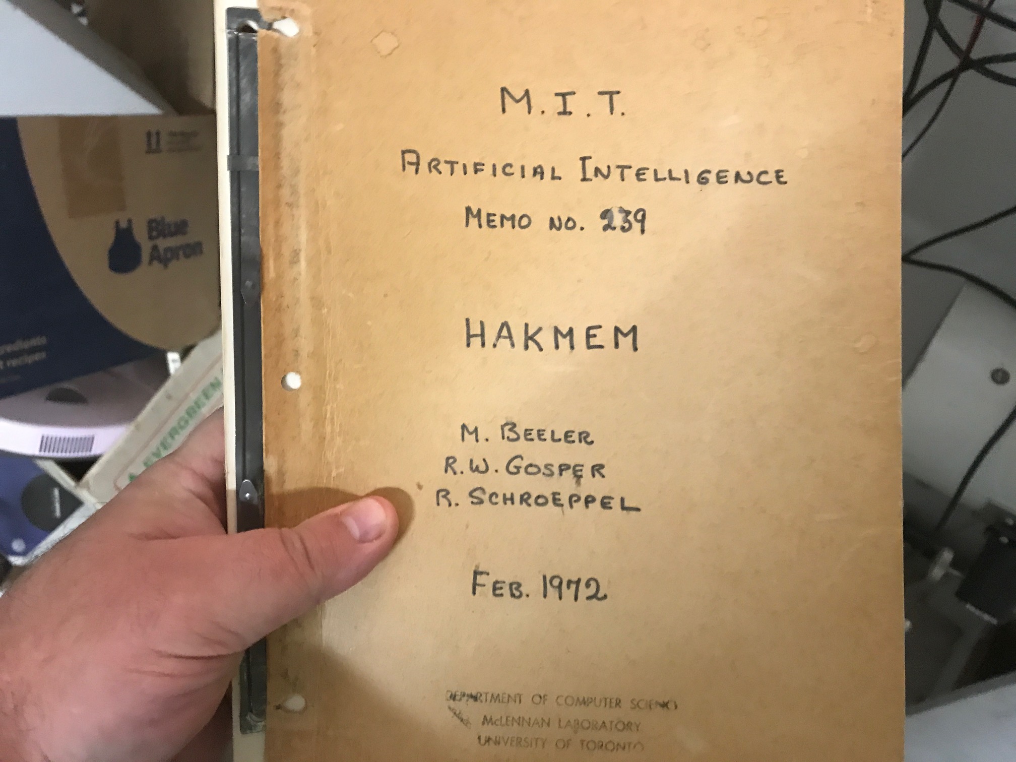
Pat Hanrahan gave me this paper to read as a prelude to explaining how his N-body radiosity stuff worked.
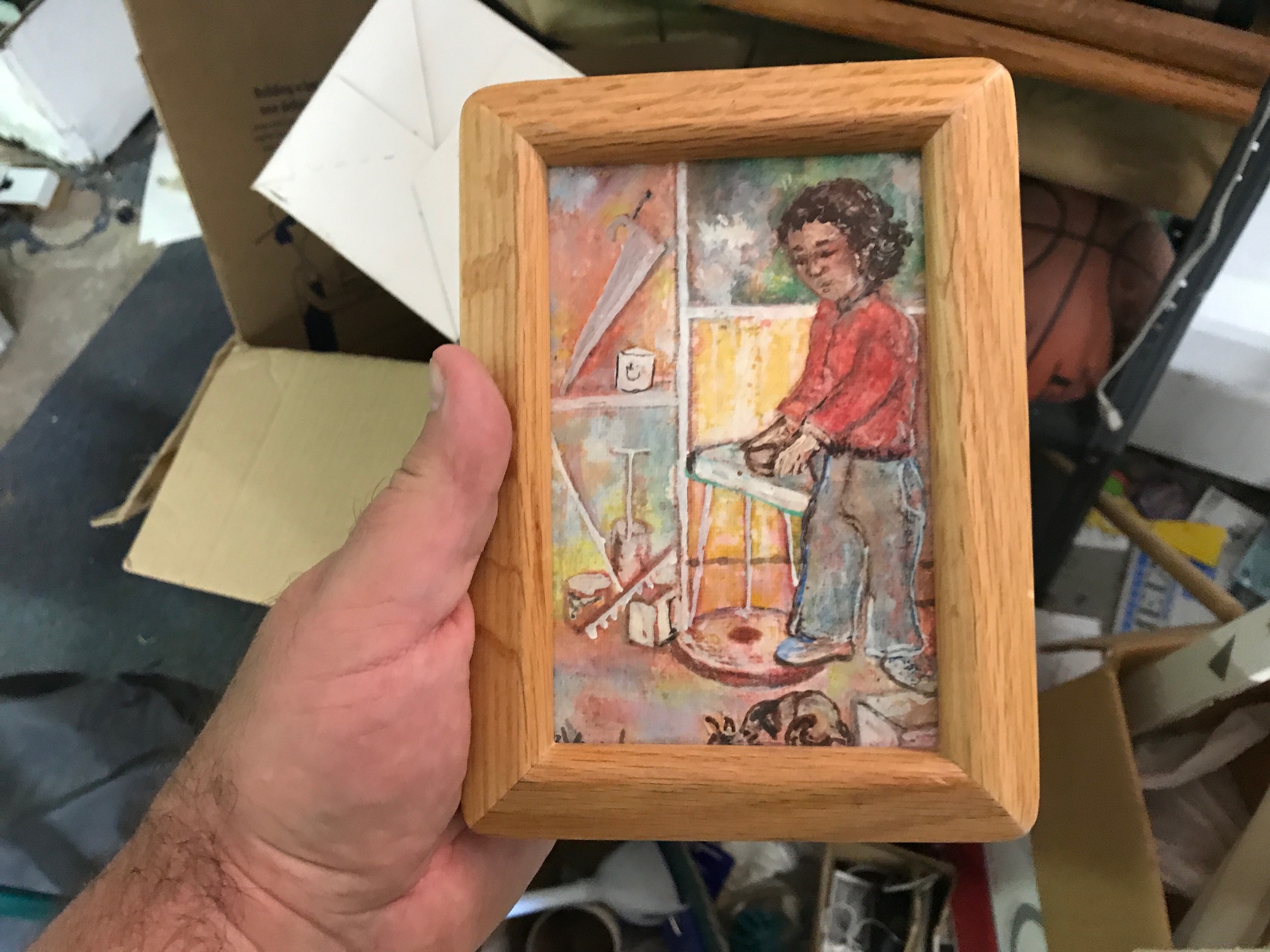
A painting done by mom, commemerating my brother, sister and I playing at the beach.
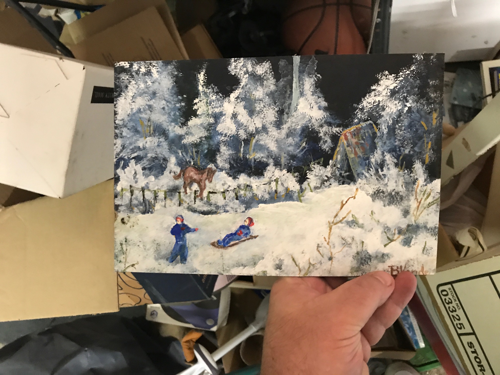
Another painting by my mom, of me and my brother during the snow storm in 1969.
Another of my mom’s paintings, depicting me grinding my first telescope.
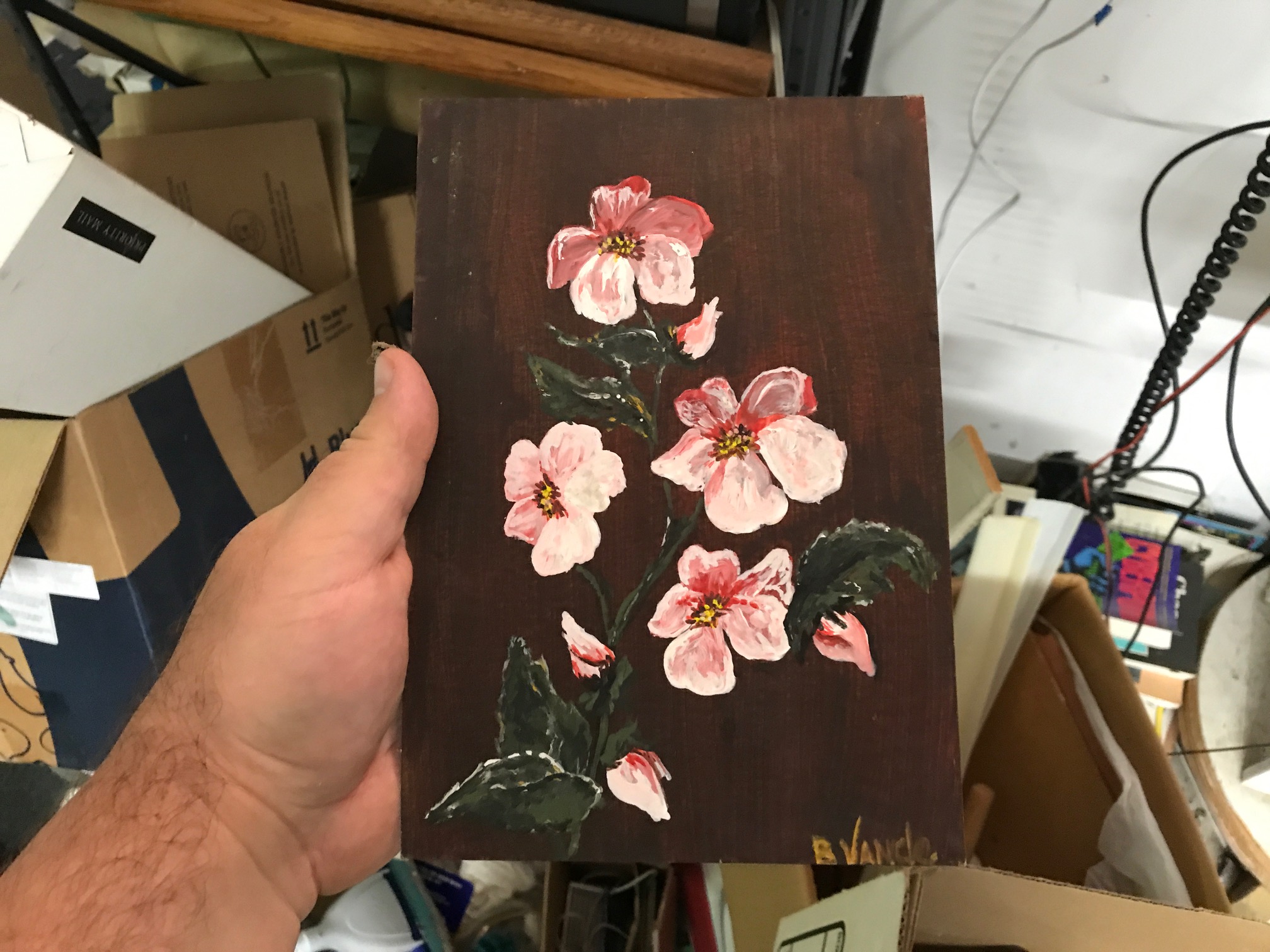
A little floral still life painted by mom.
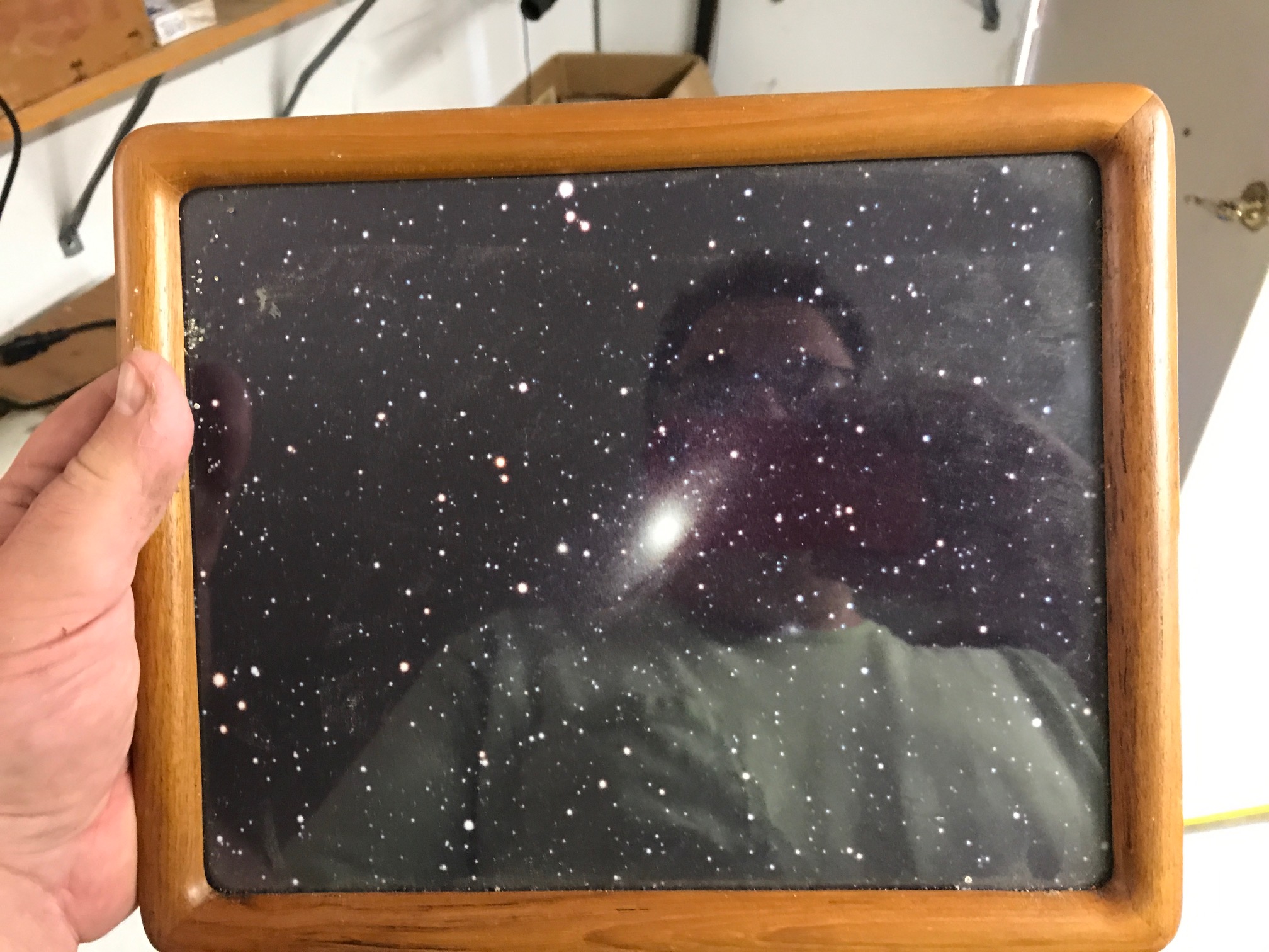
The Andromeda Galaxy, as taken by my friend Jeff during one of our astronomy excursions in college
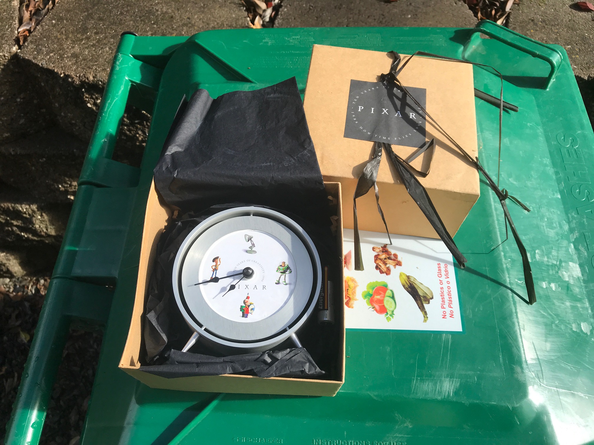
A Pixar gift from the early years
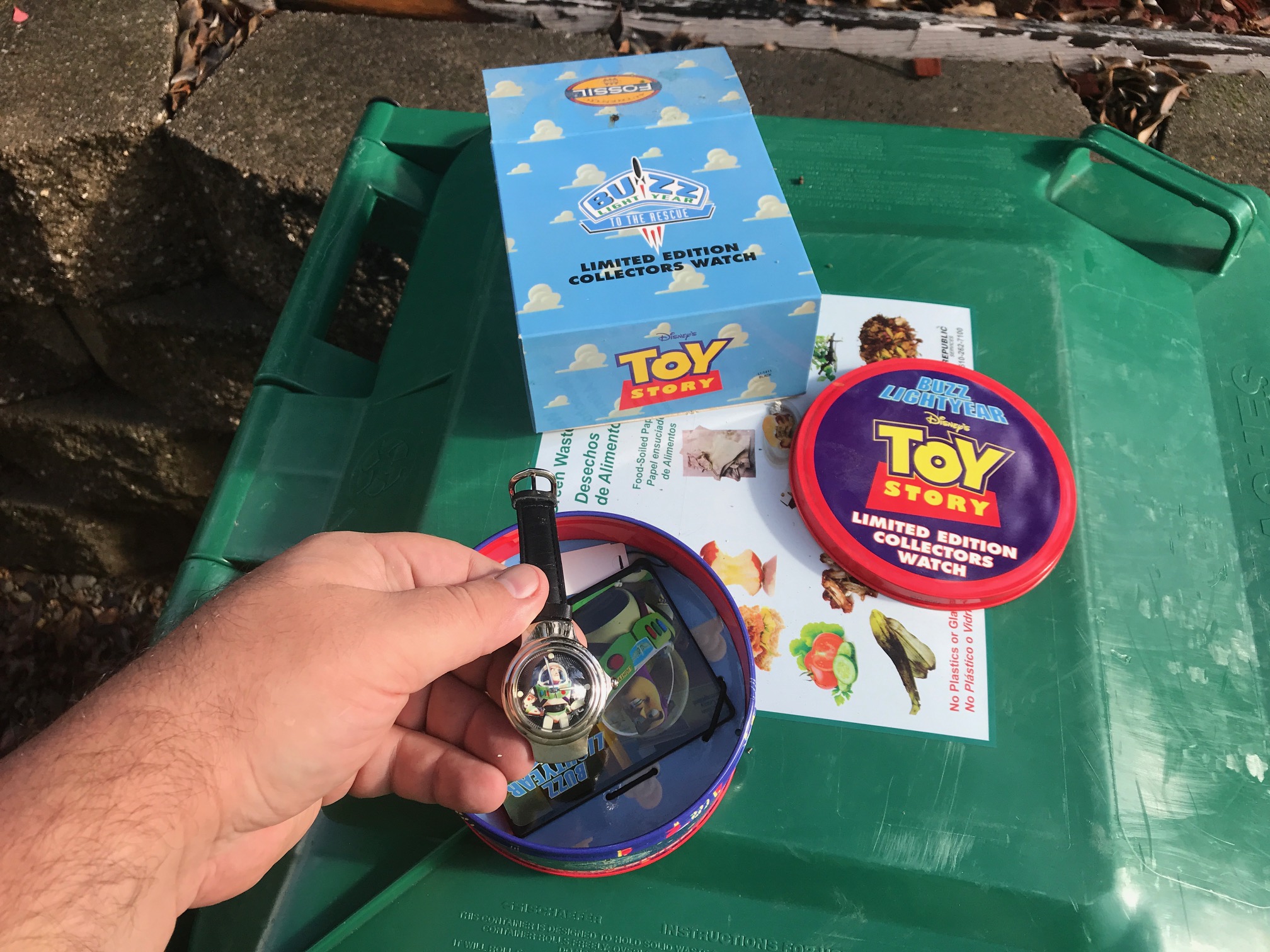
Fossil Numbered Toy Story Watch, Buzz
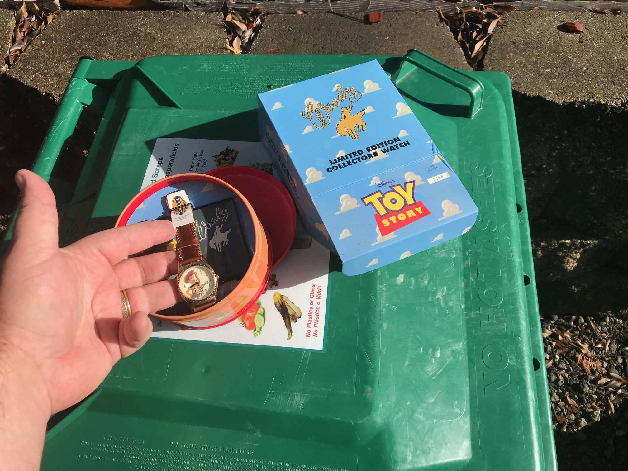
Numbered Toy Story Watch, Woody
An authentic copy of the legendary HAKMEM memo.
A D&D book I’ve probably had since I was a teenager.
A monkey given to me by Dave Rutledge of “woot” fame.
A broken disco ball ornament.
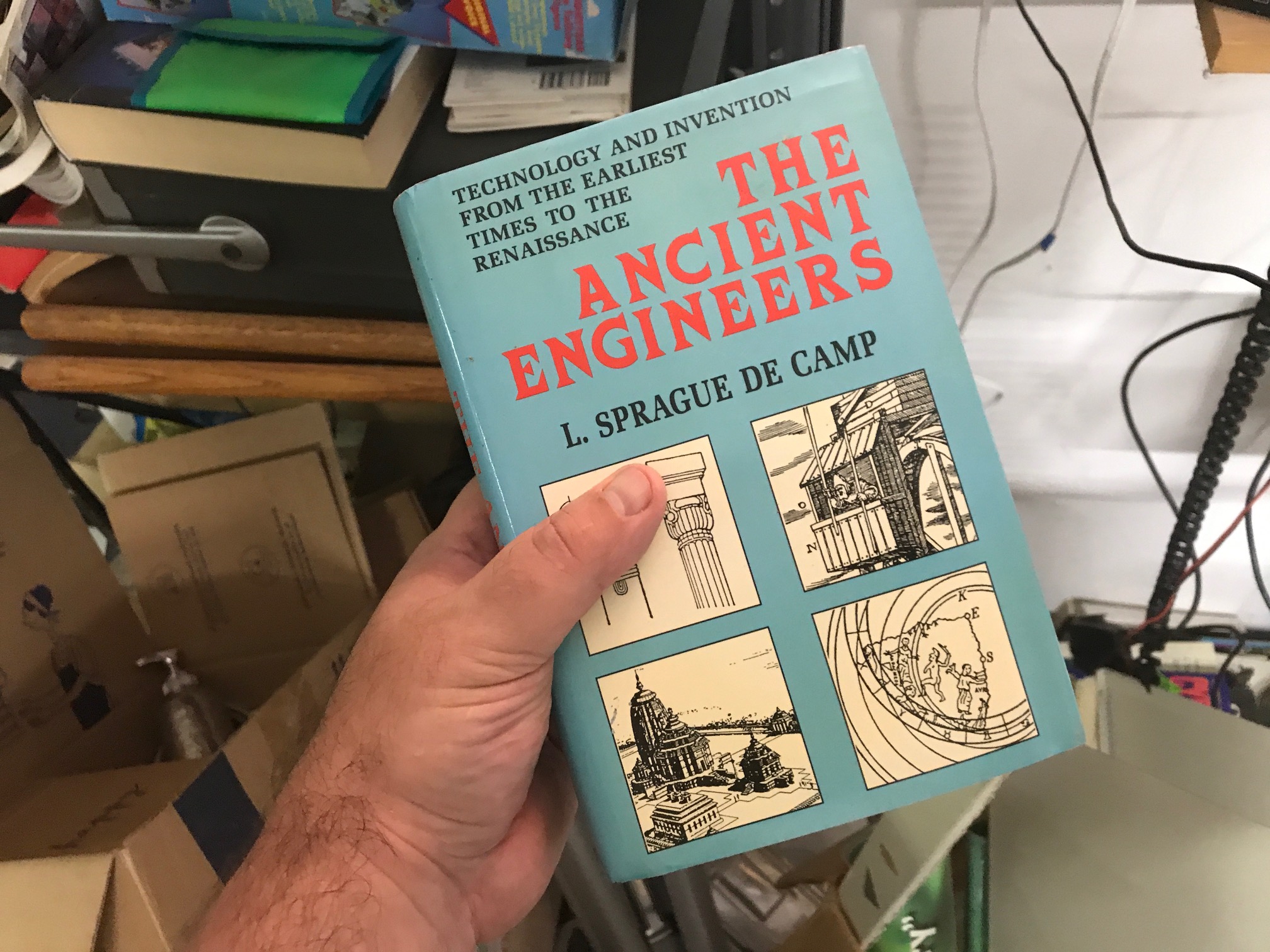
A book on ancient engineering that I bought in some bargain bin. It’s not bad.
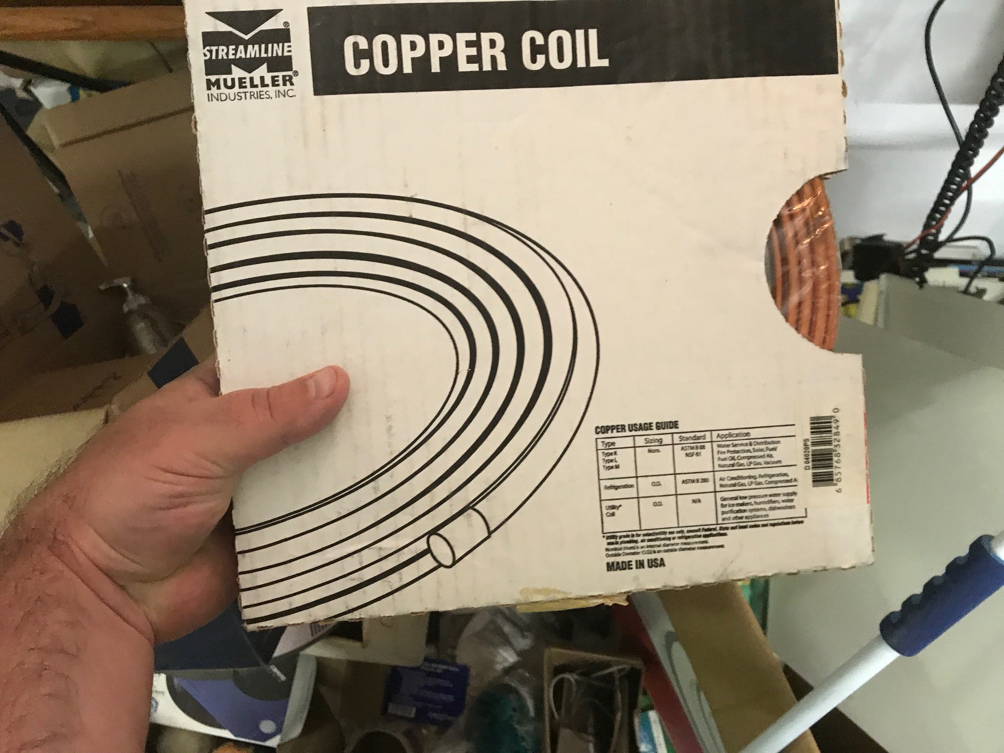
Some copper tubing that I bought to create a loop antenna.
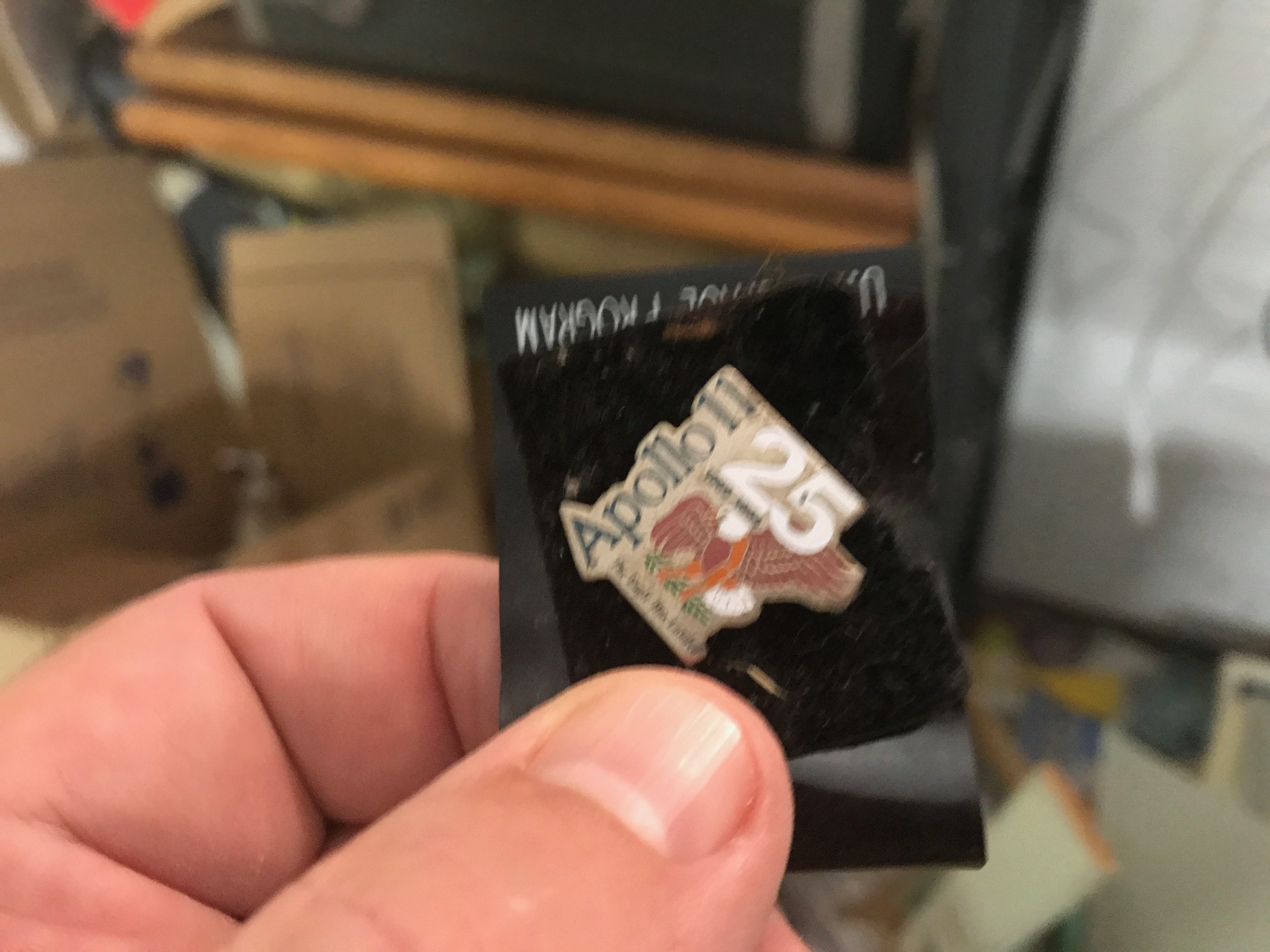
A 25th anniversary of Apollo 11 pin that I got on a trip to Cape Canaveral in 1994.
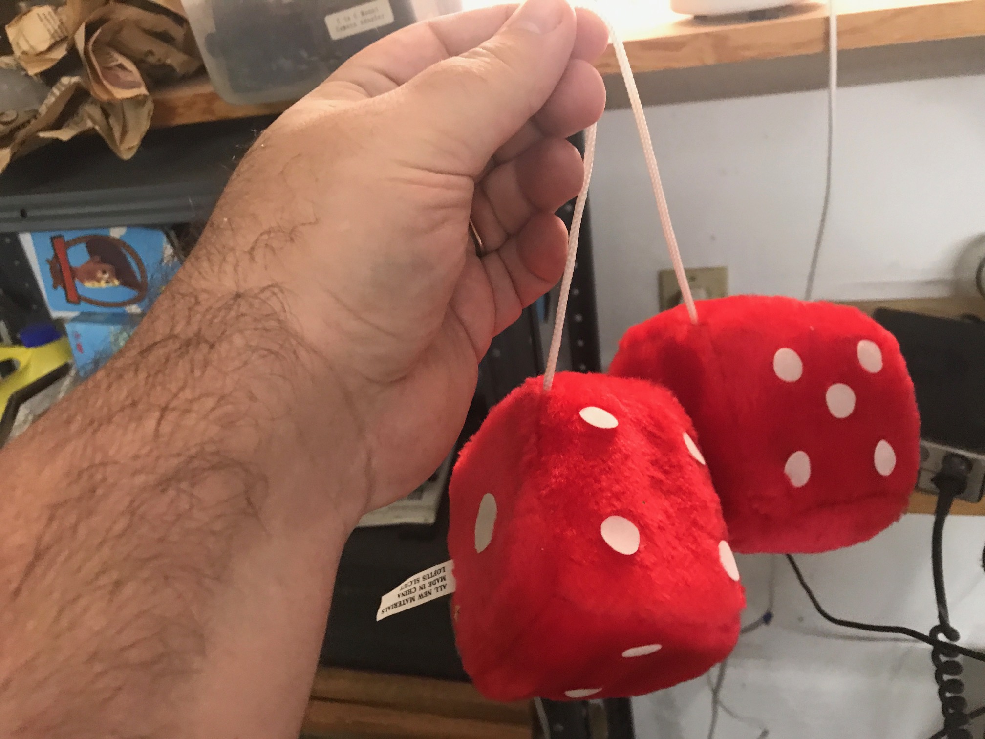
Fuzzy Dice!
As you can see, this collection indicates that I am basically a crazy person. Still, it was pretty awesome to see some of this forgotten stuff, especially the paintings by my Mom who passed away a few years ago. I am going to get these digitized, and then make sure they are reframed.
This was all a distraction, but I got through it, and moved my bench to its new location. I then thought I would try to record some video. I used a combination of hand held iPhone video for shots in my garage and webcam video of my explaining stuff, and then set about trying to cut it together in some kind of narrative using the OpenShot video editor. A couple of hours later, I realized that I was really unhappy and grumpy. Some list of my apparent grievances:
OpenShot is kind of annoying. One particular problem seems to be its lack of ability to adjust or normalize audio levels, but there are other ones too. It got really irritating.
The video I shot from my webcam on my laptop is terrible. It’s an unflattering angle, and having to look down into the camera was just uncomfortable enough to get me annoyed.
I couldn’t find my headset. I really would like to use a headset.
The video I shot with my iPhone was not very steady, and while I am generally tolerant of some degree of “informality”, it was way worse than even I was able to stand.
I really need some camera mounts. And better cameras.
So, I lost patience with it. I think there is probably still a couple of hours of work left before I have something that I will still hate. We’ll see if I can get some more work on it this week.
Toward the end of the day, I was re-examining the area around the workbench. Ultimately I want to mount a computer monitor above the bench, in the area that is currently occupied by some bad shelving that was installed by the previous owner. I decided that it should come down, so I got out my trusty Black and Decker drill and took down one small section as a test. That worked pretty well, so I hope in the next day or so I’ll clear all the remaining detritus from those shelves and take them down too. I’ve also pondered creating a mount for a camera that can be folded away but then lowered over my workbench so I can get better video. Maybe that will be something I get to in the next few days.
During this time, I had gotten a little 12v charger and put the battery back on the charger. I couldn’t find my old one, and got same day delivery on this one from Amazon. It seemed to work, but I’m a little leery of it. I had hooked up the same voltage meter that caused the issue with my system across the battery to monitor its charge. I used that as an opportunity to test live streaming using ffmpeg (perhaps the subject of a future video), and generated 46 minutes of video of a battery charging on Youtube.
I then killed the stream, and left it charging. By the morning it had risen to 14.0V, but somewhat annoyingly by the afternoon the voltage had risen to 15V. This isn’t good: the maximum voltage for charging SLA batteries is 14.4V. It appears that this ‘charger’ doesn’t have any proper overcharge protection. Still, the battery seemed none the worse for wear, but I would not advise using that particular unit to trickle charge SLA batteries.
So, late last night I rehooked up the battery, and the unit fired up and started to send telemetry. I didn’t have the solar panel hooked up, but the telemetry was working.
Except that it didn’t seen be recording temperature properly. There are two temperature sensors. The one that was part of the barometric pressure sensor was working fine. The other was returning a consistent 31.89 degrees. I suspected that something was wrong with that sensor. Since all of this was on a breadboard, it was entirely possible that I bumped a connection loose. I reseted all the jumper wires, all seemed well, and I reset.
And the sensor didn’t come back online. It wasn’t too surprising. As part of its initialization, it checks for the presence of each of the expected sensors, and if any are missing, it basically ends up in an infinite loop until the watchdog time resets. It does print out a fair amount of debugging information, but it wasn’t currently hooked to any kind of serial device (it was still configured as it was deployed in the garden). I got my laptop hooked up, and then watched it boot…
Two things seem odd: the MCP9809 was coded as if it had I2C address 0x18 (the default). A bus scan revealed that 0x18 was missing, but 0x19 was present. Odd. I changed the begin() call to point to 0x19, and reset. That appeared to work, and sent some data to the server for awhile. But then it timed out after a few minutes, and it’s been offline since.
I had always intended to restructure this code and make it more debuggable, as well as make some additional changes, but that will have to wait until later this week.
I also realized that I didn’t have a comfortable work stool. So, I ordered one. Should be hear later in the week.
Sorry that I didn’t get more done. I’ll at least try to work my way back into writing what I do down, and I really will try to make some new videos. I am pondering a “getting started with MicroPython” video, which I may live stream. Stay tuned.
November 30, 2018 | My Projects | By: Mark VandeWettering
If you follow @HackAWeek (Dean Segovis) on Twitter, you may have seen this tweet announcing a new series of videos, shockingly including my name and twitter handle.
My name is being mentioned in some pretty elevated company there. I know Dean, John, Daryl and Joe on the Tymkrs IRC channel. I know Ben mostly because of his awesome work on Youtube as part of the Citizen Science channel, but I’ve been lucky enough to meet him in person at a variety of Maker events. And I first made Jeri’s acquaintance at a hacker event that we both periodically attend. The only person I haven’t really met is Becky (hey Becky!).
All are awesome, and I’m flattered (and more than a little intimidated) to be asked to be listed among their lofty company. My own Youtube and blog presence (as anyone who monitors this channel can attest) have fallen off considerably over the last year, and I’m kind of out of the habit of producing even the meager output that I did before.
But that’s not to say that all interesting stuff has stopped in the brainwagon lair. My projects tend to be a little smaller in scope than many others, but I recognize that can also be a bonus. Perhaps some of my bits of tinkering will be less intimidating and thus will inspire more people to try and talk about small projects of their own. We shall see.
So, what can you expect from me in the month of December?
I have three projects that I currently want to work on.
Back in September, I wrote a short post about something that I have come to think of as a “solar satellite project”. Really, it was just an excuse to understand how solar battery charging works by simply building and using a small 10W solar system. My Solar Energy Project It isn’t really interesting in itself, but building it has exercised a couple of tinkering skills that are generally useful. A recent spate of bad weather revealed a problem as the battery drained out the bottom of its useful range, so currently it’s sitting on my garage workbench. As I get it back working, I’d like to talk about it a bit, and maybe see if anyone else is interesting in similar projects. My ultimate goal is to build a Raspberry Pi Zero powered system in my backyard that is entirely solar powered, and that can be used to take pictures of hummingbirds. A test run earlier this year resulted in this twenty minutes of video being recorded over the span of a day:
Next, I’d like to revisit a project of old: my LED Christmas hat. This project could use a revisit, and I am thinking of doing a remake using ESP8266 modules and MQTT to enable the hat to be controlled via the Internet, perhaps using Micro Python. I also should note that I might go ahead and crochet a custom hat to go with this project (my head is big, and many off the rack Santa Hats just don’t fit properly).
And lastly, my Creality CR-10 has been down for a while because I needed a new hot-end. I need to install that and get it back running.
So, I’ll cut to the chase. I’m going to try something new: I’m going to live stream my workshop time on the brainwagon Youtube channel. I will try to announce events a bit ahead of a time via my twitter channel so if you are interested and don’t follow me, go ahead and do so. I may or may not produce re-edited versions of these live sessions and upload them for more permanent storage. I’ll also likely include some links to other of the #nerdthunder members as well as my commentary as to why they are all awesome. Feel free to comment while I’m operating live (in fact, I think it would be awesome) and bear with me. Format, timing and exactly what I’m chatting about will likely change. I also am somewhat lacking in microphones and good video equipment, so the technical quality may not meet your expectations.
I haven’t got a lot of details about my solar project available, but Project Curacao has all the details of a much more impressive version of the basic idea to serve as inspiration. Basically, the guys at SwitchDoc decided to mount a small solar setup with some lithium polymer batteries, a Raspberry Pi and an Arduino that could gather weather and image data unattended from a location in Curacao. My own attempts are much more meager, and not in such an exotic locale, but it will serve as good inspiration.
Yes, it’s me, back after a far too long hiatus. Sometimes life intervenes, and you just have to reset your priorities. But rest assured, the geeky stuff that I used to work on and chronicle in my blog continues, and on this long Labor Day weekend, I thought I might mention a project I’ve been working on.
Long time readers of my blog may remember that I experimented with using a Raspberry Pi and a Raspberry Pi Camera module to get pictures of my hummingbird feader. Here is a refresher in case you don’t remember or didn’t see it. But at the time it was just a prototype. In particular, I never constructed a permanent setup for it. It got put back into a box, and I didn’t think about for a while. Over the last year I had major construction in my back yard, replacing a retaining wall, and our feeders were down for a long time. But that ended, and I recently started to get a tiny amount of free time. So, I thought that it would be fun to try to make a more permanent version of this project.
But I decided to do a bit more. I decided that what I wanted to do was to create a small solar powered “pod” which could be used to hold the Pi, and which could be reconfigured for other uses.
So, I bought a few goodies to help me along the way:
Allpowers 20A Solar Charge Controller I didn’t have to go with a charge controller for this project, but I thought that I might as go with one a bit beefier than I needed for this project.
ML7-12 7.2aH SLA battery I just wanted an inexpensive SLA battery to go with my charge controller.
A Newpowa 10W 12V solar panel I wanted something a tiny bit bigger than the small 6V panels that you commonly see, and again, this one was modestly priced.
As it happens, this system is probably not really enough to run an Raspberry Pi with a camera for 24/7, even with pretty good sunshine during the day. But I wasn’t sure how far off it would be, and how efficient the charge controller would be.
If you’ve never set up such a system before (I hadn’t) the basic idea is the charge controller has three sets of terminals:
the solar panel
the battery
the load, which is regulated 12v output to drive whatever it is you are powering
The basic idea of the charge controller is to make sure that the voltage and current from the solar cell are efficiently applied to the battery to charge it. The charge controller that I bought is also supposed to prevent over discharge by disconnecting the load from the battery if the voltage drops too low, and which also is supposed to prevent overcharging.
So, I thought I would test it out.
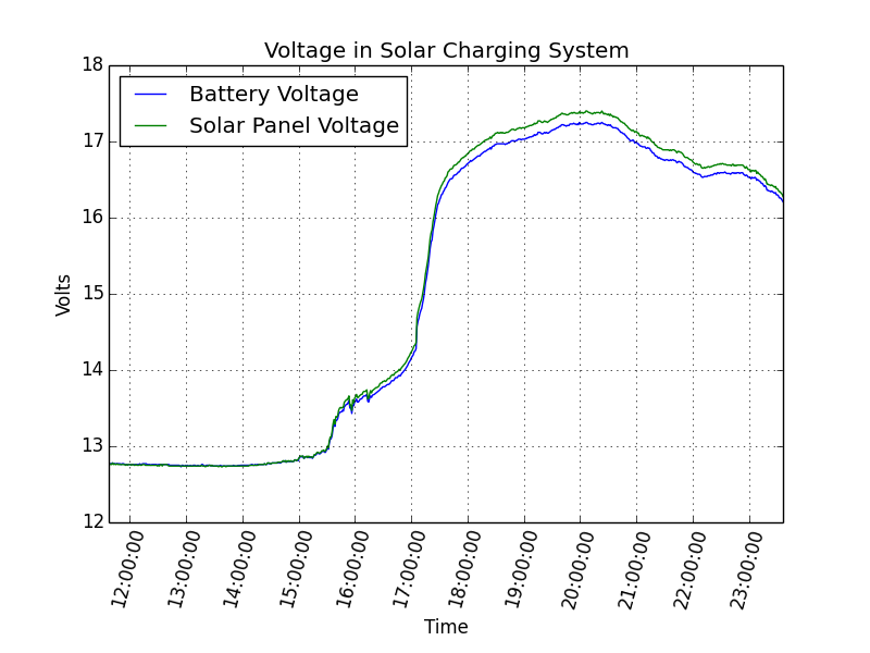
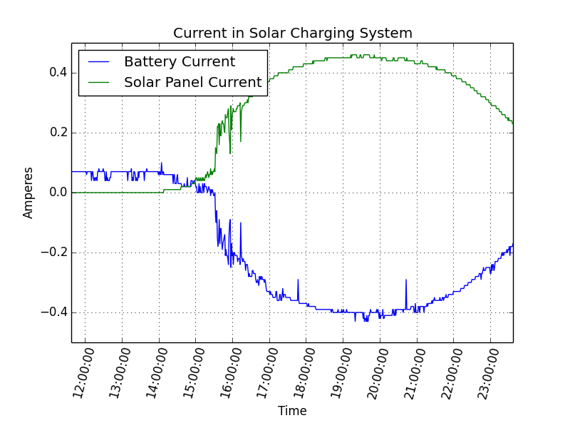
Instead of using my Raspberry Pi, I dusted of a WEMOS D1 Mini, my preferred < $5 ESP8266 module. To it, I connected a pair of INA219 modules, one that would read the battery and voltage directly from solar cell, and the other that would do the same for the circuit that leads to the battery. The ESP8266 would take all these measurements once a minute, and would upload them to the Adafruit MQTT server. You could view them directly from their dashboard, but I downloaded 24 hours of data, and made some graphs using matplotlib. The sensor data from the solar panel are in blue, whereas the data from the battery is in green.
Some of the data makes sense to me. Looking at the current data, you can see that the graph starts with no current from the solar panel, as it is starting in the dark. We see that there is a current running out of the battery (it’s discharging) at a rate of somewhere around 70mA. But as the sun rises, we begin to get current from the solar cell. It’s current climbs, and the current into the battery falls, eventually reversing as it begins charging the battery. That all seems great.
But here is what confuses me. If we look at the voltage, sunrise occurs around 15:00 UTC and the voltage begins to climb. It goes up, and up, and up. I believe that I had the “overcharge” setting to be around 13.7v. I would expect that as the solar panel becomes more brightly illuminated, it would pass that level, and I would expect the charge controller to reduce the amount of current to the battery. But we really don’t see that. The current stays quite high, eventually topping 0.5A at 17V, or about 8.5w. This doesn’t seem good to me. The voltage on the battery terminals gets quite high (topping 17v) and I’m worried that it might be overcharging. I’ve double checked my hookup, the settings on the controller, and I’m baffled.
Can anyone provide any insight as to where my understanding might be going astray?
I’ll eventually write up a complete description of this project, so if any of this doesn’t make sense and you have any questions, feel free to leave comments and questions, and I’ll try to explain further. Eventually the code and other bits of information will show up here.
February 13, 2018 | 3D printing | By: Mark VandeWettering
So, I got a new 3D printer about ten days ago, a Creality CR-10. While this printer requires a bit of assembly, it is in general a much nicer printer. It has a 300x300mm heated bed, a control box which is actually in a case that won’t electrocute you, and is constructed from aluminum channel which makes for a much stiffer platform.
This is not to say that it has been entirely easy to get going. When I initially assembled it, I had some difficulty getting the alignment just right. Unlike the Anet A8, the Creality CR-10 has a single stepper driving the Z axis up, powered by a single leadscrew mounted vertically. While I am not exactly a mechanical engineer, I do not think this is actually a very good scheme, and indeed, the upgraded version of the CR-10, the CR-10S has dual leadscrews. But in any case, when I initially powered up, it was clear that the X axis wasn’t level, and getting it to be level is a bit of a hit and miss process. Eventually, I loosened the right side of the carriage and evened the tension, and got it to travel approximately level. After that, I leveled the bed, and was off to the races.
I initially had some difficulty getting PLA parts to stick to the glass bed (I’d never used a glass bed before). Eventually, I just covered it with blue painters tape, lowered the first layer print speed. and we were off to the races.
I spent most of Saturday night and Sunday printing the parts for a small quadcopter. The CR-10 uses a Bowden extruder, which means that I had to tune the retract settings, but overall they came out very well. I’ll do a separate writeup when I get them assembled.
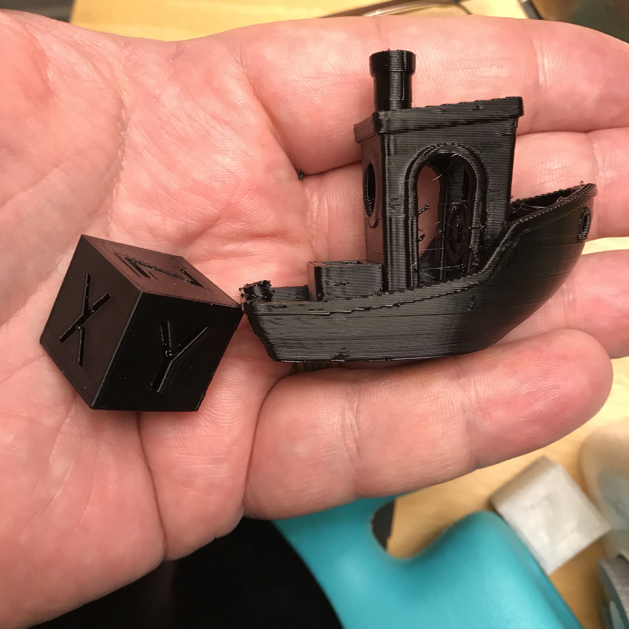
I then decided to try something more challenging, and use some PETG filament. PETG requires higher temperatures, but is supposed to be even sturdier. I printed a calibration cube which turned out very nicely, and then did a quick “Benchy”.
The print quality overall is pretty good. The cube was especially nice. The Benchy shows some rounding of the corners, a few little surface blemishes and stringing. I’ll have to work on improving the quality with some tuning, but given that I’ve really only had two days of experience with the printer, and less than an hour of experience printing PETG, I’m pretty happy.
This is just a short set of updates for my weekend projects, meant to keep me in the habit. I’ll write up a more complete version of these projects going forward.
First of all, a new acquisition. My Anet A8 3D printer has proven to be, well, not the most reliable of gadgets. I still haven’t gotten around to fixing its heated bed, but should get to it shortly. But as it happens, a small windfall came my way, so I decided to get a Creality CR-10 which I caught on a good price for less than $400. Unlike the laser-cut, hours-to-assemble Anet A8, the Creality is mostly assembled. It has a 300mmx300mm bed, a much taller range of travel, and is constructed by aluminum extrusions that make for a nice, stiff, and easy to assemble printer. I mostly assembled it in a little less than an hour, but ran out of steam and decided to go to a movie with Carmen and then watch the Superbowl. I’m hoping to print a Benchy when I get home tonight: the only thing I have left to do is get the bed leveled.
I also spent some more time on the ISS clock. I added a new display mode that shows details of upcoming passes, including a diagram of the pass, showing its path across the sky and its maximum elevation. I also updated the epoch that the Plan 13 code was using so that it would be more accurate, and now it compares to within about a degree or so with what other, more sophisticated models have. There are still a couple of lingering glitches. Occasionally it looks for the next pass before the current pass is complete. I suspect that is because I used a number of global variables to communicate between processes, and something in the logic isn’t quite right. But as they say, any program worth writing is worth rewriting. I’ll try to get a version of the code up on github tonight, even though it’s kind of embarrassing.
Stay tuned for CR-10 print experiences and more on the ISS clock.
I haven’t posted an update here recently, but I am (mostly) living up to my New Year’s resolution to spend at least 30 minutes a day working on a project. This has taken the form of some stupid but necessary chores (like fixing the broken pull cord on my lawnmower) but has mostly taken the form of additional incremental additions and improvements to my ISS clock project. This has mostly taken the form of noting a small deficiency, and then working until that deficiency is ameliorated.
The ESP32/Arduino environment still has access to the FreeRTOS operating system below to create tasks, semaphores and queues. I decided that I would implement the program as a set of tasks of different priorities. One task’s job is to compute the current latitude, longitude, altitude and azimuth for the satellite. Another lower priority task scans forward in time, and finds the next time when the satellite rises and sets. When it finds those, it pauses until the current time is beyond the found set time, and then continues searching for the next rise/set pair. The final task runs the display, showing all the current information. If the time of the next satellite rise time (or AOS — Acquisition of Signal) is set, then the display process will give a countdown in hours/minutes/seconds.
This was all working reasonably well, except that I noticed that the time display would frequently “jump” a second, skipping from 42 seconds to 40 seconds in countdown, and sometimes even in the clock display jumping from 10 to 12 seconds for example. I didn’t think any critical path in the code would account for anywhere near that amount of delay in switching between processes, but tried reorganizing the code in various ways to be sure.
In the end, I realized that it had nothing to do with multitasking or the like. I had written code in two different places to convert an internal representation of time used by my Plan 13 satellite library into H:M:S format, and had committed the same error in both locations.
The thing that I realized is that unlike normal Unix time calls, internally my code represents the current time of day as a double which represents fraction of a day. To step the time forward by one hour, I increment that value by 1/24. I have a function whose purpose is to convert this internal representation separate hours, minutes, and seconds.
Here is a (slightly edited) version of my original code.
[sourcecode lang=”cpp”]
void
DateTime::gettime(int &h, int &m, double &s)
{
double t = TN ; // TN is the time in fractions of a day
t *= 24. ;
h = (int) t ;
t -= h ;
t *= 60 ;
m = (int) t ;
t -= m ;
t *= 60 ;
s = t ;
}
[/sourcecode]
The problem appears to be rounding interacting with the timing of the display process. Staring at this code, I’m not sure what I was thinking. I rewrote this code in the following way:
[sourcecode lang=”cpp”]
void
DateTime::gettime(int &h, int &m, double &s)
{
double t = TN ; // TN is the time in fractions of a day
int ts = (int) round(t * 24. * 60. * 60.) ;
s = ts % 60 ;
ts /= 60 ;
m = ts % 60 ;
ts /= 60 ;
h = ts % 24 ;
}
[/sourcecode]
This code works much better. I had coded a similar routine in new code which had the same error. I must admit that I’m still a little fuzzy about how the timing of the display process interacts with this rounding issue to introduce the errors that I observed, but I suspect it has to do with the fact that I inserted delays in the display process to keep that process from updating somewhere around two times a second. I think that the prediction task (which runs for about twenty seconds usually) may be starving the low priority display task just often enough to cause the rounding error to manifest.
I’ll ponder it more later.
Things that are now percolating to the top of my todo list are to understand the event handling of the NtpClientLib library. Occasionally it will toss errors from the WiFiUdp.cpp file, and error handling is not appropriate (sometimes it doesn’t set time properly). I suspect I’ll have to dig into the networking code in the library a bit deeper.
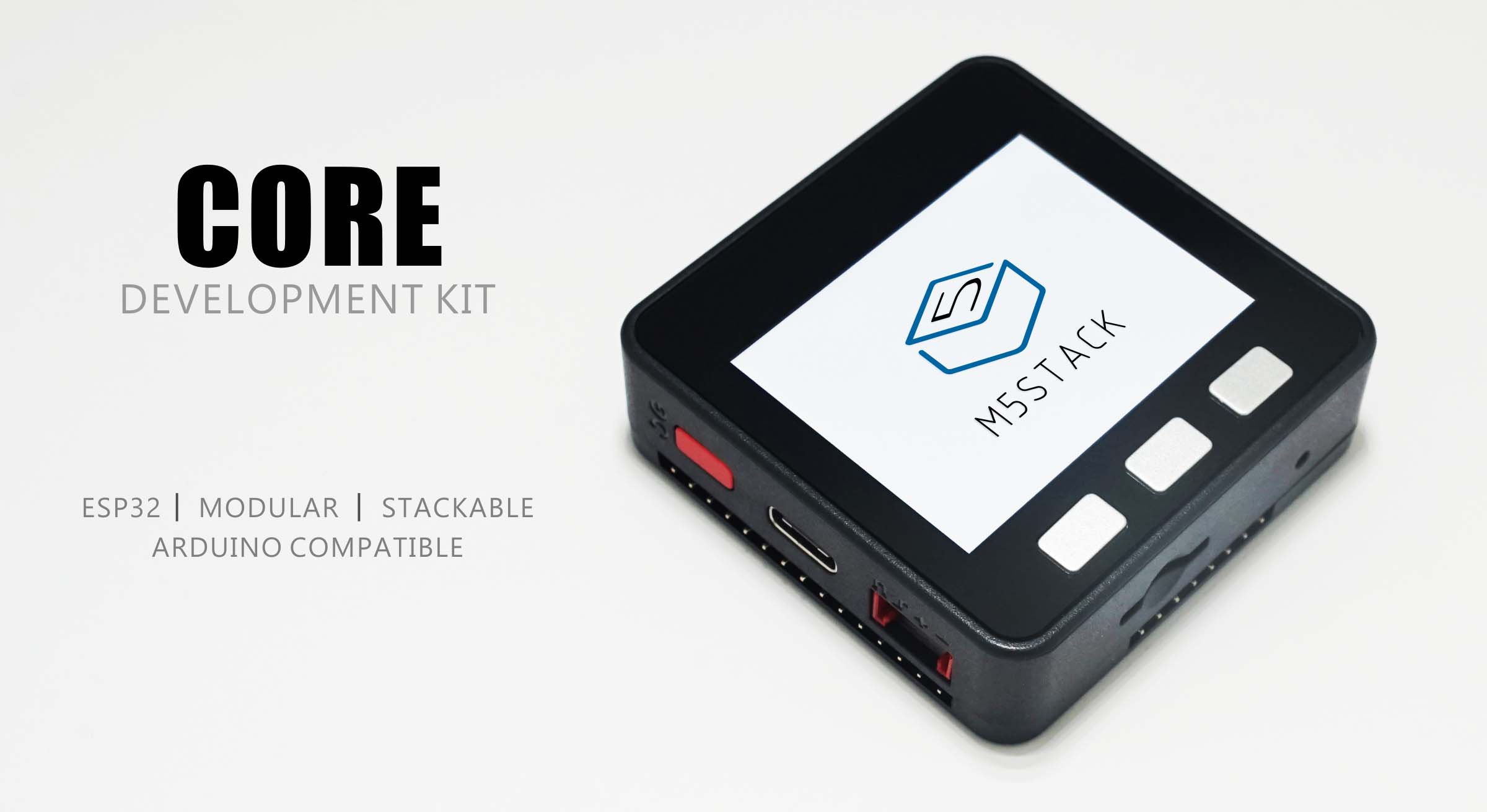
Addendum: The display on this thing is one of those tiny 0.91″ OLED displays. It’s really at the limits of what I can comfortably read, and I’d like to have more space (and potentially color). I have some small 1.8″ LCD boards, but I stumbled across the M5Stack board which appears to be available on banggood.com. It looks like a cool little box.
I ordered it from this link on banggood for about $33. Besides having an ESP32 module, it includes a case, a 320×240 2″ color LCD panel, and three buttons. The larger display size and buttons are a great fit for my ISS project. When it arrives, I’ll quickly work on a port of this code to that.
If that doesn’t work, I’ll probably work on adapting it to some of the ST7735 modules I have lying around that I ordered from icstation.com.
Stay tuned for more progress, and eventually links to the git repository for the code when I am not embarrassed by the code.
Several days ago, I cobbled together a short bit of code to make an NTP enabled clock out of an ESP32/OLED module. I had previously used an ESP8266 and a separate module to make a little demo that predicted the location of the ISS. I thought that the ESP32 would make a better development platform, for a number of reasons:
It’s faster.
It is dual core.
It includes a small real time operating system that allows you to create communicating tasks.
My early example didn’t make any use of that, it was just a clock. So today I spent a little more than an hour to expand the basic code outline to include some new features:
It now links in my C++ library that implements the Plan 13 algorithm for doing satellite prediction.
The previous NTPClient library wasn’t really very good: it didn’t include any way of accessing day/month/year. I switched it to use NTPClientLibinstead, which is much better.
I experimented with using the xTaskCreate call to create different tasks, one of who updates the current satellite position, and the other which updates the display. This proved to not be difficult and works remarkably well. I anticipate that this will make my final version of the code easier to write. I can implement one process whose job it is to scan forward in time, looking for the next satellite pass. When it finds one, it can use a queue to send it to the display task, and can continue. This makes the program easier to write and more modular.
I also did some work to fetch orbital elements directly from celestrak.com so that the display will always be up to date.
The code is not in a state to share yet but I think it is going to be pretty neat when I’m done. The gadget could easily be mounted in a small case and carried into the field, where it could be entirely battery powered.
I’m Mark VandeWettering, former senior technical director for Pixar Animation Studios, and (for the moment I’m a husband and father and grandfather. I like telescope making, radio, and all sorts of other things.
Latest Comments
I recall burning three or four weeks of a sabbatical getting Saccade.com on the air with Wordpress. So much tweaking…
I move my pretty useless blog to Hugo about 7 years ago, since I got frustrated at too many security…
Something I used to good effect for a while was a "Pocketmod". You take a single page, fold it a…
Bloat is a serious problem, to be sure, but I'm not aware of many modern programming languages that avoid it.…
I'm running static pages (Notepad++) and a couple instances of Wordpress, and an instance of dokuwiki, all on ubuntu on…


I recall burning three or four weeks of a sabbatical getting Saccade.com on the air with Wordpress. So much tweaking…