Monthly Archives: February 2011

Hershey Vector Fonts

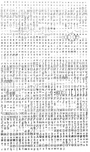
Nearly thirty years ago, I remember hacking together some simple code to display graphics on a WYSE 35 terminal. The terminals supported the TEK 4014 graphics commands to draw vectors, and I found the original “Hershey Fonts”, created by A.V. Hershey at the U.S. National Bureau of Standards, and placed in the public domain.
I’ve come full circle it appears. Having some vector fonts for my oscilloscope experimentation would be really handy. I had nearly forgotten them, until my friend Tom reminded me of them. Digging around found Paul Bourke’s cool web site which archived a lot of this information, and provided a quick, cogent explanation of the data:

The full Hershey set is supplied here for Roman

via Hershey Vector Font.

Pixels Past Circuit Boards

I’ve done a couple of Atari 2600 projects in the past: my Pong clock and my Enigma Machine simulator. To make physical realizations of these projects, I relied on some boards that I bought a few years ago from AtariAge, but when I checked a few months ago, it appeared that they had stopped selling them in their store. It wasn’t a big deal, but I did consider the fact that at some point I might want to have some more PCBs for future projects.

Luckily, the guys at Grand Idea Studio did all the heavy lifting, and have PCBs not just for the Atari 2600, but also many other classic video games systems, including schematics and Gerber plot files. Archived for a future project.

Pixels Past Circuit Boards | Grand Idea Studio.

Animated Vector Graphics on an Oscilloscope

I lost the original edit to this post. Recreated.

So, while watching the Oscars, I decided to hack together a simple little graphics program that would allow me to generate more sophisticated graphics for the oscilloscope. I ended up with 263 lines of code that implemented a simple matrix-based set of graphics commands. Eventually, I’ll add some line clipping and some other graphics primitives, but for now, it seems to be working just fine.

YouTube – Animated Vector Graphics on an Oscilloscope


To give you a taste of what the library lets you do, here is the set of commands that I used to generate the animated dial you see in the film.

[sourcecode lang=”C”]
void
Dial(double seconds)
{
int i ;
TransformPush() ;
fprintf(stderr, "… angle %lf\n", seconds*6.) ;
Rotate(seconds*6.) ;
Line(0.0, 1., -0.05, -0.05) ;
Line(-0.05, -0.05, 0.05, -0.05) ;
Line(0.05, -0.05, 0., 1.0) ;
TransformPop() ;

for (i=0; i<360; i+= 6) {
TransformPush() ;
Rotate((double) i) ;
if ((i % 30) == 0)
Line(1.0, 0., 0.90, 0.) ;
else
Line(1.0, 0., 0.95, 0.) ;
TransformPop() ;
}
}
[/sourcecode]

Addendum: Congrats to Lee and all the Toy Story 3 crew, and to Randy for winning his second Oscar (with twenty nominations, incredible). He definitely has had the best speech of the night so far.

Using an oscilloscope as a graphics display device…

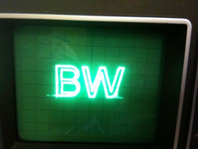
I’ve been meaning to do a project like this for quite some time. The basic idea is to write a program which can generate sounds which drive the oscilloscope in X/Y mode so that it will draw graphics on the screen. After an hours worth of tinkering:

There is obviously some bugs, so I am not going to put up any code or the sound file right at the moment, but here’s what I learned:

  • Choice of sound card matters. The default sound card in my laptop does a really crappy job. I’m not sure whether it is resampling the audio at some lower rate, but it never worked properly. I dusted off my EMU 0202 USB based card to do this demo, which works much better.
  • My oscilloscope doesn’t have a Z input, so it’s always drawing. To hide the “moveto” bits, you probably want them to be as quick as possible, which means that if you have two contours, the best way to draw them is to draw one starting at one extrema of the outline, and then connecting it to the most distant point of the other loop when you shift to drawing it. While drawing, you go at a much slower rate, and try to maintain a constant velocity.
  • I’m not sure why the inner loops of the B overlap the outer outline: I’m suspecting that the oscilloscope may be in some sort of AC mode, where a cap is stripping some part of the DC component. I’ll have to think of this some more.
  • I obviously have a bug in my outlines as well.
  • When I get a better written and more illustrative chunk of code, you can expect it to show up here.

Addendum: I worked on it a tiny bit more, and found a bug in my program, and that I had left the scope in “AC” mode for XY, which meant that it was passing the input through some kind of capacitor to strip the DC component. When I toggled that off, I got a much better version, where the inner loops of the B don’t cross the outer loops. Still not sure why the trailing edge of the W rings so badly.

Arduino + MCP4725 Breakout Board

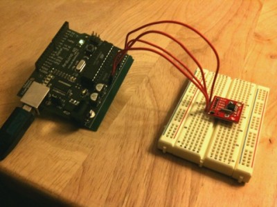
Well, the other I2C based breakout board I got from Sparkfun was for a Microchip MCP4725 DAC. It’s a 12 bit device, and will eventually do duty controlling the voltage controlled oscillator in my beacon transmitter. For tonight though, I just wanted to make sure I could program it, so I soldered on some header pins, plugged it into a breadboard, and coded up a small, simple program to simply send values from a table holding appropriately scaled sine values as quickly as possible. Here’s the code:

[sourcecode lang=”C”]

#include <Wire.h>

void
setup()
{
Wire.begin() ;
}

#define MCP4725_DEVICE 96

int sintab[64] = {2147, 2347, 2545, 2737, 2922, 3100, 3267, 3422, 3564, 3692, 3803,
3898, 3975, 4033, 4072, 4092, 4092, 4072, 4033, 3975, 3898, 3803,
3692, 3564, 3422, 3267, 3100, 2922, 2737, 2545, 2347, 2147, 1947,
1747, 1549, 1357, 1172, 994, 827, 672, 530, 402, 291, 196, 119, 61,
22, 2, 2, 22, 61, 119, 196, 291, 402, 530, 672, 827, 994, 1172,
1357, 1549, 1747, 1947} ;

int sp = 0 ;

void
loop()
{
Wire.beginTransmission(MCP4725_DEVICE);
Wire.send(64); // cmd to update the DAC
Wire.send(sintab[sp] >> 4); // the 8 most significant bits…
Wire.send((sintab[sp] & 15) << 4); // the 4 least significant bits…
Wire.endTransmission();
sp = (sp + 1) & 63 ;
}
[/sourcecode]

And here’s the brief YouTube video showing it in operation:


DS32kHz 32.768kHz Temperature-Compensated Crystal Oscillator

In considering the long term accuracy of the RTC chip that I was playing around with, I did some additional thinking and reading. My understanding is the error comes from the accuracy of the crystal oscillator: the 32.768Khz timing crystal probably has an accuracy of 20ppm or even larger. My guess is that this is expressed in two kinds of instability: a long term bias, which conceivably could be trimmed using a trimming capacitor, and a thermal component, which could be solved by temperature control. But in digging around, it appears that Maxim makes there own temperature controlled crystal oscillator, that has errors down in the 2ppm per year over a temperature range of 0 to 40 degrees Centigrade. Pretty nifty. They come in DIP (but non-stocked @ digikey) and various SOIC/BGA packages, with costs that might average around $10, which seems a bit spendy, but worth considering.

DS32kHz 32.768kHz Temperature-Compensated Crystal Oscillator – Overview

Kenneth mentioned the DS3232 as a more accurate version of the DS1307: it appears to me that the specifications for it are identical to the specification for the DS32kHz TXCO. My guess is that it’s simply an integrated package, but I haven’t had the chance to look at the datasheet yet. It does appear to be cost effective: you can get them from digikey in quantity one for less than five dollars. Worth looking into.

Addendum: Kenneth could have plugged his own excellent page on his build of a DS3232 based clock. Very nice, and includes a supercapacitor backup circuit for the DS3232. As it happens, I picked up a couple of supercaps from sparkfun with this order: I might have to give this a try.

Arduino + DS1307 Real Time Clock

Okay, this is no big deal: lots of people have done it before. But while I was watching TV, I soldered some header pins to the DS1307 based real time clock board I got from sparkfun.com , and coded up this simple program to read the time from it. I’d never really used the Wire library, but it’s pretty straightforward. I plugged the board into a breadboard, jumpered it into the Arduino, and with a bit of tweaking, it works.

[sourcecode lang=”C”]

#include <Wire.h>
#define DS1307_I2C_ADDRESS (0x68)

byte h, htmp, m, s ;
byte dow, dom ;
byte mn, yr ;

byte
BCDToDEC(byte val)
{
return (val >> 4) * 10 + (val & 0xf) ;
}

void
doDate()
{
Wire.beginTransmission(DS1307_I2C_ADDRESS) ;
Wire.send(0x0) ;
Wire.endTransmission() ;

Wire.requestFrom(DS1307_I2C_ADDRESS, 7) ;

s = BCDToDEC(Wire.receive() & 0x7f) ;
m = BCDToDEC(Wire.receive()) ;
htmp = Wire.receive() ;
dow = BCDToDEC(Wire.receive()) ;
dom = BCDToDEC(Wire.receive()) ;
mn = BCDToDEC(Wire.receive()) ;
yr = BCDToDEC(Wire.receive()) ;

if (htmp & (1<<6)) {
/* 12 hour mode… */
h = BCDToDEC(htmp&0x1F) ;
} else {
/* 24 hour mode… */
h = BCDToDEC(htmp&0x3F) ;
}

if (h < 10) Serial.print("0") ;
Serial.print(h, DEC) ;

Serial.print(":") ;
if (m < 10)
Serial.print("0") ;
Serial.print(m, DEC) ;
Serial.print(":") ;
if (s < 10)
Serial.print("0") ;
Serial.print(s, DEC) ;

if (htmp & (1<<6)) {
if (htmp & (1<<5))
Serial.print("PM") ;
else
Serial.print("AM") ;
}
Serial.print(" ") ;

Serial.print(mn, DEC) ;
Serial.print("/") ;
Serial.print(dom, DEC) ;
Serial.print("/") ;
Serial.print(yr, DEC) ;
Serial.print("\n") ;
}

void
setup()
{
Wire.begin() ;
Serial.begin(9600) ;
}

void
loop()
{
doDate() ;
delay(1000) ;
}
[/sourcecode]

Nothing earth shattering here. Eventually, I want my beacon controller to have a real time clock, and this seemed like a good way to go. Having a reasonably accurate real time clock means that I can make my beacon send WSPR messages, which start at the beginning of even numbered minutes on the hour. Baby steps.

PCB Order via DorkbotPDX

A while ago, I remember hearing that DorkbotPDX had some deal where you could submit PCB designs and have them ganged with other designs and manufactured for a pittance (or at least, a small number of pittances) but I hadn’t bothered to chase down the details. Recently, I’ve thought of making a small board with an Atmel AVR, a RTC and maybe a DTC to use in (among other things) my beacon controller so I looked it up. Pretty neat: three copies of any board you submit with a cost of $5 per square inch. Thus, if you have a 2″x1″ board, you get three copies for $10. They can also do 4 layer boards for $10 a square inch. Nifty.

PCB Order | DorkbotPDX.

Students to photograph Discovery flyby at 100,000 feet | TG Daily

Interesting. A group of students are launching a high altitude balloon “some miles” from the launch site of the Shuttle Discovery at Cape Kennedy, and will be streaming the video of the event as recorded by a pair of Android phones on board. I suspect that any video so streamed will be less than stellar, but I like the basic idea. I’ll have to check back and see how they did.

Students to photograph Discovery flyby at 100,000 feet | TG Daily.

Dennis Klaat on Formant Synthesis

I’m in serious danger of digressing into trying to learn more about speech synthesis. The discovery of CSpeak, it’s relatively lack of intelligibility and inability to properly formulate consonants has me oddly intrigued though. I’ve been digging for more information, and the source code for rsynth yielded a link to:

Dennis Klaat’s Software for a parallel/cascade formant synthesizer

Klaat’s synthesizer includes a 40 parameter model (compared to the 7 from CSpeak) and includes at least some limited tables for vowels and consonants. it also includes FORTRAN (ugh) for the model. I’ll have to look at it more carefully, but bookmarking it for later consumption.

Addendum: The comp.speech archive might have some useful bits in it, including implementations of this model.

Your first Digital to Analog Converter

To control my simple Beacon, I used PWM and as simple (but slow) RC filter. That worked good enough for a test, but I really wanted the voltage changes to be more rapid. What alternatives are there? Well, I actually ordered a $5 I2C DAC board from Sparkfun, but it hasn’t arrived. The obvious low-tech alternative is to use a R-2R resistor ladder. Somewhat coincidently, hackaday had a tutorial on them just a few days ago.

Your first Digital to Analog Converter build – Hack a Day.

Addendum: This page talks about the need for a buffer amplifier to be used in concert with the D/A converter. That’s because any load (resistance) you place on the output works in concert with the resistor network to change the output voltage. If that load varies, it will also cause your output voltage. By buffering through a buffer amplifier (in this case, a rather cheap op amp) you prevent all that, and the DAC works more reliably.

Battle of Speech Synthesizers: CSpeak vs. Festival

Okay, this kind of like watching “America’s Most One Sided Fist Fights”, but I was diddling around with Cspeak, which is a speech synthesizer that is just 150 lines of code long, and thought I’d try to see just what quality it was capable of.

Well, it’s (not surprisingly) pretty hard to understand most of the time. Try this out:

CSpeak, reciting one of my favorite works of fiction.

Pretty hard to grok. It’s not just that the consonants are poorly represented, it’s got all sorts of oddly confusing changes in prosody and pitch which make the sentences really difficult to track. Did you figure out what work of fiction this was from?

You could cheat by listening to the same synthesized from Festival.

It’s interesting to surf over to Dennis Klatt’s History of Speech Synthesis and listen to some of the historic speech synthesizers, and decide where CSpeak falls in terms of legibility when compared to other historic speech synthesizers. I also liked this page on pre-electronic and pre-digital attempts at speech synthesis, which had some remarkably cool machines dating back to the 18th century.

CSpeak and Cantarino

Yesterday’s surfing churned a couple of interesting links on the subject of speech synthesis and computer singing. I wasn’t really explicitly looking for this stuff, and can’t reconstruct what led me here, but I thought I’d archive this here. The first is a link to a formant based speech synthesizer in just 150 lines of code. The quality is, well, not amazing, but the code is simple enough to follow, and enabled me to gain a grasp of formant synthesis, at least, with a little explanation from Tom.

CSpeak – David A Roberts.

They have a video too!

Apparently this is derived from Cantarino, a project to do speech synthesis on the Arduino. It can sing too, and a bit better to my ear.

Cantarino — Speech synthesis on the Arduino

Arduino sings ‘Daisy Bell’ from Tinker on Vimeo.

Both of these synthesizers have difficulty doing consonants in an intelligible way, but it is fascinating that such a simple technique can approach legible speech at all. Bookmarked for future tinkering.

The Ham’s Inconsistent Love/Hate relationship with Progress and Technology

WARNING: pontificating and ranting ahead. You’ve been warned.

Tom pointed out that I had an inadvertent markup error which ended up dropping several paragraphs of this post. It is now corrected.

Julian, G4ILO followed up yesterday’s post about technology not being good for ham radio with a nearly equally confusing one today entitled Platform for progress. I find it confusing because the over the bulk of it, I’m entirely in agreement. He says that there are a (presumably significant) number of technophiles who get involved in amateur radio, only to drop out immediately when they realize that it isn’t a replacement for the cell phone or Internet because the infrastructure isn’t as extenstive or reliable as they expect. I’d agree that is probably true, although it’s hard to say that hams who never really become active have any actual negative effect on the hobby.

He then goes on to criticize the existing top end of HT radios, and in most respects I agree with him. When I compare the level of technology that’s inside my VX-8GR to the level of technology inside my two year old iPhone 3GS, the difference is palpable. But I think that’s mostly unfair: after all, the iPhone is cutting edge mass market product, with sales in the millions, and the VX-8GR will probably sell a few tens of thousands of units. And, of course, the IPhone’s purchase price is in most cases heavily subsidized by high fees from the cell phone companies which are simply not available to ham radio manufacturers.

But even taking those things into account, the state of the art in ham radio HTs is maddeningly primitive, and in ways that make operating your radio more difficult and more confusing. My VX-8GR has impossibly small buttons in an undistiguishable array on the front. Many important functions require pushing both a function key on the side and then a button on the front, a maneuver which cannot be done with one hand, and if you were left handed, require a very odd grip. The display is small and often fails to contain useful information, while commonly cluttered with information you don’t need. All the APRS functions are hidden behind the need to hit the MODE button, which puts you in a different mode, with different setup options, and a similarly bewildering method for navigating among APRS messages. Programming memories is (as it is on virtually all radios) a similarly mystifing barrage of error prone button clicks. It’s simply horrible.

And yet, it’s probably one of the better and more capable radios out there. Go figure.

Julian’s vision of how HTs could be transformed is remarkable, and I wish that ham radio manfuacturers would listen to him. While some people criticize attempts to make things easier to use as “dumbing down”, I completely disagree. No good purpose is served by poor interfaces, even for experts. It’s ridiculous how much effort it takes to get a radio programmed with local repeaters. I recently did this for the VX-8GR, and it involved:

  • Buying a custom cable and software, because even if you had the cable (which is of course not a standard type), you still can’t find software to program the radio for free, despite having spent $350 on the radio.
  • Surfing over to K5EHX’s awesome repeater site and downloading an export of all the local repeaters.
  • Loading them into the software, and then deleting obvious duplicates and bad data.
  • Organizing them into banks.
  • Adding a bunch of FM satellite frequencies, along with Doppler shifts for satellite operation.
  • Adding in APRS setups for both terrestrial (144.390) and satellite (145.800) frequencies.

I can imagine a world where I plug the radio in, visit a website, and all this happens automatically. Would this be dumbing down amateur radio? Of course not. It doesn’t take any particular intelligence to program a radio: it’s just a bit of tedium that could reasonably be automated. But the state of the radio art is a long way from making this happen. What’s more, because most radios hide behind undocumented protocols and stupid non-standard cables, it isn’t even possible for guys as clever as K5EHX (who programmed and maintains the repeater maps himself) to step up and make life easier for everyone.

So, Julian and I are in violent agreement, right up until the end of today’s post, where he says:

So why won’t this happen? I guess the reason for that is that Yaesu, Icom, Kenwood and the rest don’t make cellphones. Their business is making radios that are intended to be as dumb as most of their users. Ham radio is just an offshoot. The market just isn’t big enough to justify developing what for them would be a completely different and unique hardware platform. So I guess for the foreseeable future we’ll be stuck with our geeky walkie talkies and the cool stuff will all be on cellphones.

Argh. First of all, I don’t see how anything good comes out of insulting a bunch of your fellow hams. Our own intelligence lies along a continuum, and while I admit that there are a lot of people considerably stupider or less experienced than I, there are also a whole bunch of people on the other side who are considerably smarter and more experienced. It’s hard to understand how calling other people stupid actually enhances ham radio. James has pointed out that Julian was likely referring to business and public radio users as being “dumb”. I’ll strike the previous paragraph as a misunderstanding of his point. I do think that Kenwood, Yaesu and Icom don’t design ham radios the way they are because of any conviction that their radios need to be simple (in fact, I’d say that they are needlessly complicated to use, as my examples above were meant to indicate) but that simply they have successfully sold radios of similar design, and their isn’t enough competition for them to invest in improving them in significant ways. I also think it is possible (but I have no evidence to support it) that there might be some fear that a significantly new and radical architecture for radios might be met with some trepidation by hams, who have a reputation of not being the most progressive and quick to adopt new things.

Secondly, it presumes that technological advances in ham radio must come from manufacturers. Even today, that simply isn’t true: modes like APRS and PSK31 were originally designed by amateurs, and have been copied and extended by amateurs until the manufacturers took notice, and are just now being adopted as features in products. We also see software defined radio in inexpensive amateur kits like the Softrock, and now adopted into semi-commercial products like The SDR Cube. My guess is that you’ll see a commercial offering of similar capability reasonably soon. My point: we can serve to lead and inform manufacturers what technology we find interesting by developing it ourselves, and creating a market for it..

Lastly, I’m exasperated by the fatalism that is expressed by these kind of statements. Here and in the responses to yesterday’s article, Julian expressed doubts that “ordinary hams” could learn enough about SDR or acquire the ability to work with surface mount parts. I’m baffled by this kind of negativity. Here in the U.S. we are regulated under Part 97, which says that the amateur radio service was created to allow for self training, experimentation and advancement of the radio arts. It doesn’t say anything about mastering “just the easy bits” or “just the non-software bits”. Julian also made the claim:

Those that have the expertise to experiment with new technologies in ham radio probably learnt those skills professionally. The reason why I am against the incursion of advanced technologies into this amateur hobby is that it forces more and more of us true amateurs into being mere appliance users.

I don’t really mean to pick on Julian, but I find this to be almost entirely wrong. First of all, everything I know about amateur radio, electronics, digital signal processing and microcontrollers I learned because of personal interest, and I know literally dozens of people of similar stories. And of course, there have always been skilled amateurs in our ranks who learned their material as professionals, and brought their skills to amateur radio. Julian appears to be saying that the participation of skilled, professionally trained people in amateur radio is undesirable. I find that baffling.

I also think his conclusion is odd. To me, the inclusion of software technology into amateur radio serves as an incentive to bring large numbers of skilled software engineers into the ranks of amateurs, enabling new applications and new techniques. The vision I have for the future of amateur radio is one where we are more more engaged, not less. Furthermore, if we drag our feet in adoption of technology, amateur radio as a whole becomes increasingly irrelevant as the rest of the world advances in technology. We simply become a kind of technological re-enactment society, like a kind of radio Rennaissance faire. (Apologies to those who like Renaissance faires…)

Ham radio is a very odd endeavor: for an activity which is centered around one of the greatest advances in technology in human history, we have a surprisingly large number of people who treat it with mysticism, who want to hold it just at the level that they themselves feel comfortable, and who resist efforts to change or advance it. There are radio amateurs who are obsessed with tube rigs, and refuse to consider modern solid state design. They’ll tell you there is something just inscrutable about transistors, but the truth is, they’ve never manufactured a tube, and for the most part, tubes are just as inscrutable as transistors. SImilarly, there are people who refuse to use ICs in their rigs, because somehow it just seems to be “cheating” to use a device that integrates more than one gate in a package, even though making transistors is just as inscrutable as making ICs. You’ll find people who don’t want microprocessors, so they do crazy things like using 555 timers in reckless abandon, with all sorts of diode based switching, when a $2 Atmel chip will do the same and more for less money and actually with less circuitry.

Julian’s blog has lots of really cool stuff, stuff that has inspired and challenged me to learn and do more. I hope he continues with it. Like him, I’m eagerly awaiting G3XBM’s DSB 10m rig design, and hope to be constructing one. I’m still playing with beacons, and APRS and other things that he’s interested in. I just wish we could send out a consistent, careful message to our fellow hams and potential hams to be that technology and amateur radio aren’t strange bedfellows. We are the Amateur Radio Service, not the Antique Radio Society.