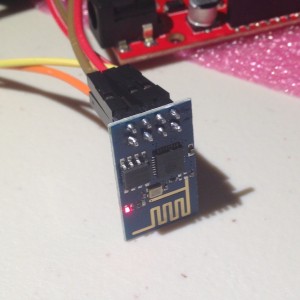
First electrons for the ESP8266…
 In the telescope making world, we call the first time that a telescope is used to look at the sky “first light”. I’ve decided to call the first time I load some code onto a new development board “first electrons”.
A few weeks ago, when I did a video that illustrated some of the bucket of development boards that I had lying around, I decided that I should at least make a sincere effort to try to do something, anything, with each of them. Since then, I’ve discovered platformio which has enabled me to at least get some code running on the more obscure ARM based boards that I had lying around. Buoyed by that positive experience, I sought to see how I could get code running on some of the other boards. Tonight’s board was the ESP8266, a little cheap board (I paid $6 or so for mine, I’ve seen them on eBay for as little as $3) which are often used as serial-Wifi links, but which actually include a nifty little 32 bit SOC.
Luckily, the gods have smiled in the form of a three part article (Part 1 Part 2 Part 3) by Alasdair Allen for Make magazine. Previously, getting code to compile onto the ESP8266 required finding the right version of gcc and the download esptool, configuring it… Who has the time? What’s awesome is that now you can download a version of the Arduino environment that already has the necessary compiler and tools installed, and use the friendly, comfortable Arduino environment to compile and run code.
So, tonight, that’s what I did!
Conveniently, I had an 3.3V FTDI serial cable that I had purchased back when I was experimenting with 3.3V boards. That’s convenient, because otherwise I’d have to wire up a 3.3V voltage regulator, which isn’t hard, but at least takes one more step. Using the diagram in Part 2 of the article listed above, I setup some jumper wires to connect it all up. I then downloaded the necessary version of the Arduino environment (for my Linux laptop), installed it, loaded the WifiServer example application, modified it with my own network’s SSID and password, and tried compilation. It compiled fine, but when I tried to download the new code to the ESP8266, I got a communication error. I double checked all the connections against the diagram, no dice. Hmmph. There was one small bit of confusion that I always have when hooking up serial devices: the RX (receive) pin of one side needs to be connected to the TX (transmit) on the other, and vice versa. But when you try to document this, it can be confusing: if an end of your cable is labelled RX, does it mean that you should attach it to the RX? Or that the other end of the cable is RX, so you should connect it to TX?
I swapped RX and TX. And voila. The download works just fine.
To reboot and run the code, you need to remove one of the ground connections from the boad and cycle the power. I then fired up the serial monitor, changed the baud rate to 115200, and then watched it boot. It printed out that it was attempting to connect to my network, printed a series of periods, and eventually reported it’s IP address.
Nifty! I need to go dig up some current limiting resistors (maybe 220 ohms or so) so I can test it, but I verified that if I accessed http://192.168.1.116/gpio/0, it turns the gpio pin low, and http://192.168.1.116/gpio sends it high. Voila!
Well, with a few caveats. It seemed a little unreliable, and seemed to hang a couple of times. I’m not sure what the deal is. I’m suspicious about how much power my FTDI cable can actually supply, maybe that’s part of it. Or it could be software related. I’ll have to play with it more to be sure. But it’s pretty nifty. I’m sure I’ll be playing with it more. Good stuff.
Addendum: I dug up an LED and a 330 ohm current limiting resistor, and then recorded this trivial little demonstration.
I recall burning three or four weeks of a sabbatical getting Saccade.com on the air with Wordpress. So much tweaking…