I’ve been wanting to make a computer-controlled mechanical gadget for quite some time. When I finally got a 3D printer a little more than a year ago, I began to think of how I might make a device that could direct a pen under computer control. I even took the time to order a CNC shield which could be used to drive the four channels needed for a 3D printer, but I never really got too far on that project. The NEMA-17 steppers that I ordered have largely sat in a box.
Until a couple of days ago. I wanted to do something, but maybe wasn’t quite ready to embark upon a project as complex as a 3D printer or CNC milling machine conversion. If the cost was low enough, it wouldn’t matter if the thing I built was particularly great: I would learn enough by doing the project to make it worthwhile, and I would gain confidence that perhaps would make me enthused enough to try a bigger project.
Hence, the computer-controlled Etch A Sketch project was born.
I’m of course far from the first to do such a thing. I didn’t let that particularly bother me. I sometimes refer to my hobbies as “timidly going where others have gone before,” and this is no exception. I knew that I wanted to use two of the steppers I had on hand, and probably use the CNC shield that I had. A quick order to Amazon Prime had a nice shiny new Etch A Sketch delivered to my house, and I went to Thingiverse to see what kinds of brackets and adapters people had used on their project. I settled on this set of parts and set my newly repaired and functional Creality CR-10 to printing the new parts.
There were a couple of issues. The original page didn’t have STL files for all the parts, you had to refer to older projects to get the STL files for the larger gears. When I printed one, I found that the center hole was significantly loose. Luckily, the author had uploaded the OpenSCAD file for generating the gear. Reading through the code, I found that the shaft hole was set to a diameter of 5.25mm, whereas a quick check with calipers revealed that mine were more like 4.5mm. I went ahead and printed a new one and tested it. It was a very tight press fit, which was just what I wanted. Huzzah!
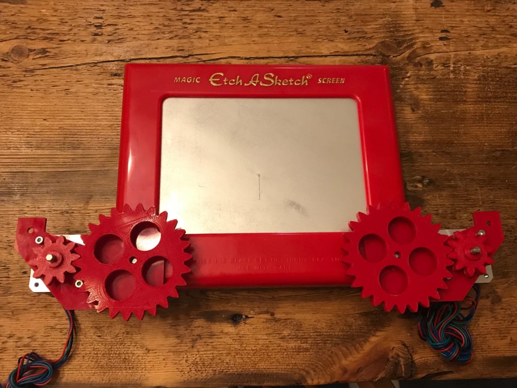
The two mounting brackets are curved to fit the front panel and are to be attached with hot glue. I was dubious about this, but a reasonably large amount of glue was spread and the brackets pushed into place. It seems to work rather well, and it looks like they will hold just fine. I then pushed the two gears onto each side. There was a little bit of vertical misalignment: the large gear on one side was originally pushed quite deep, and didn’t mesh well with the smaller gear when it was in place. I used a flat bladed screwdriver to pull it back away from the body until it lines up pretty well. As yet, I don’t have any code to drive the motors, but turning the shaft by hand seems reasonably easy and the amount of backlash or slop is, well, probably not a big deal.
My intention was to drive the two steppers with a system like GRBL, which is a G-code interpreter that is used to drive CNC machines using an Arduino and some stepper drivers (provided by the CNC shield that I mentioned above). But as of this moment, I seem to be having some difficulty configuring the software. I may actually instead just write some simple code to test the stepper motors (perhaps by driving the steppers to draw a square on the Etch-A-Sketch) before I try to anything more complicated. It really wouldn’t be hard to drive the steppers using a simple set of drawing commands: all I’d need to do is dust of the Bresenham’s algorithm that I learned back in my early teens, and I’d be good to go. Next step is to read up on the wiring for the CNC shield wiring, and get the 12V supply running to the steppers to power the gadget. It might also be good to 3D print a stand to hold the Etch A Sketch in a more upright position. Hopefully, by the next time I post about this, I’ll have some video of it doing something nice.
Stay tuned.