Tag Archives: 3D Printing

Steps toward getting a BLTouch Bed Level Sensor on my CR-10…

I’ve had my Creality CR-10 for quite some time, and fairly early on I decided that I needed a bed leveling sensor. It wasn’t just because it was difficult to level the bed. The bed itself isn’t anywhere close to flat. Since the printer doesn’t know that, you have all sorts of problems with adhesion. To be honest, I’m not 100% certain I understand what math the bed leveling sensor does (it’s been on my list to understand). Let’s say that the bed has a 0.1mm crown in the center. Does this make the printer lay down a first layer which is 0.1mm thinner in the center? Or does it distort the print so that the first layer actually follows that contour and maintain a constant layer height?

I don’t know, but for now I don’t care. I just wanted it to work better when laying down the first layer to make sure that it stuck.

So I ordered the easiest bed level sensor solution I could find: the EZABL from TH3D. It’s not super cheap, but it’s convenient and didn’t require any soldering. They also have a version of the Marlin firmware available (the TH3D Unified Firmware) for download which is simple to configure for a wide variety of printers and directly supports their hardware.

And it works… okay.

About 9 times out of 10 I’ll get a good first layer. But every once in a while, the calibration will be twitchy, and something bad will happen. I think that ultimately it boils down to lack of repeatability. The sensor is a non-contact capacitive sensor and it appears to me (without scientific testing, and no slander intended) that the repeatability of probing (especially if I haven’t let the sensor heat up for quite a while) is pretty low. I’ll probably investigate that further, but in the mean time I thought it might be worthwhile to consider using a different type of sensor entirely: namely, a BLTouch, which uses a contact sensor. This has the advantage that whether I print on the aluminum bed, on tape, or on mirror tile I usually do, it will sense the actual surface that I’m printing on. That seems good to me, and the BLTouch has been pretty well regarded.

So I ordered one. Not super cheap either. You can get cheap clones on AliExpress, but I didn’t feel like waiting. With Prime I received mine yesterday.

The Bullseye duct…

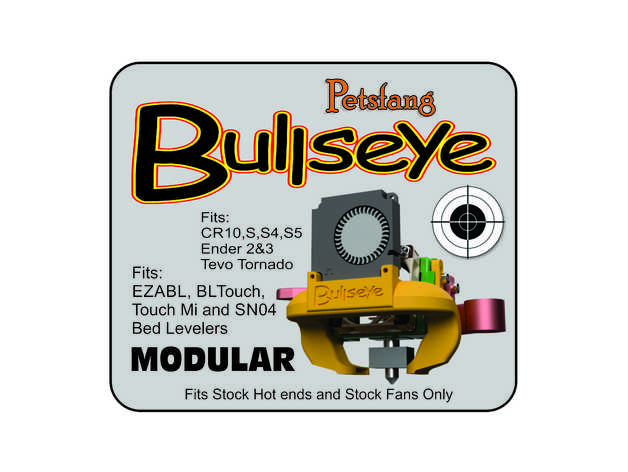
So, I started thinking about installing it. I knew that I’d need a different mounting to put it on my printer. I had been using the PetsFang duct with the EZABL, so I thought about printing another one, but I noticed that they had updated a new design called the “Bullseye” which seemed to fix a few mechanical issues that I didn’t especially like with the original. It was also a modular design that enabled me to print holders for either the EZABL or the BLTouch, so that seemed like a good thing. I downloaded the parts and it took about six or seven hours to print all the parts.

Now, onto firmware and wiring…

And here’s where this project turned into a bit more of a headache than I would like. In a previous posting, I complained that the MELZI motherboard in the CR-10 used an ATmega1280 which has just 128K of flash. As it happens, the firmware that they’ve jammed into the CR-10 is really close to the limit. Thus, when you add new features to the firmware, you are often playing a game of “what features do I enable or disable to get it to fit.” This game is annoying. When I was using the TH3D Unified Firmware, they had done a lot of the work already, but the BLTouch is not (or badly) supported by recent versions of their firmware. The stock Marlin is a bit of a rats nest though, and while it does use platformio to compile (which I love), getting the configuration options set up properly is not a lot of fun.

But it gets worse…

The BLTouch sensor has basically five pins which need to be wired to it, and the MELZI motherboard doesn’t direct support for it. The usual solution is to hijack the pin that provides the buzzer sound (pin 27) and hijack it to control the BLTouch. This requires a bit of wire snipping and soldering, or you could use a board which looks like this:

Pin 27 adapter board…

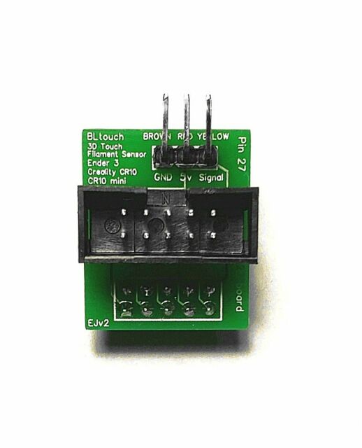
It’s a dumb little board whose purpose is to inject itself between the the connector for the display and the motherboard, and then breaks out the right pin to the side where you can easily attach the BLTouch. It’s got no active components on it at all: just a 10 pin IDC socket, with 10 header pins on the bottom and three 90 degree header pins on the side.

And they sell for a ridiculous amount of money (one seller on Amazon charges $20 for this little adapter board.) Absolutely insane. I’m pondering spending an afternoon to dust off my meager KiCad skills, draw up a quick PCB board, and have a bunch made by JLC PCB, as well as making the Gerber files made available so you can make your own. Stay tuned for that.

And I’ve found it difficult to find instructions that compile a reasonable version of Marlin for such a configuration. If I get time this weekend, I’ll try to work my way through it and document it so that any humble reader who stumbles across this can make one for himself.

Okay, that’s it for 3D printing this weekend. Have fun melting plastic.

A few thoughts on 3D printing and the Creality CR-10

A name plate, printed in two different colors of PLA filament on my Creality CR-10.

Over the last couple days, I’ve been pondering my journey through 3D printing. After having taken a three month break from it (more on that below) I’ve managed to get my Creality CR-10 back up and running in a reasonable way, and have donated my Anet A8 (my gateway drug to the world of 3D printing) to our hacker space at work, and I’m slowly tinkering it back into fighting shape. Last night I decided to try the “change filament” option in the Marlin firmware for first time, and it worked really well. I made the name plate pictured on the right, first by laying down the base in Fire Engine Red PLA I had, and then once the layers with the embossed lettering started, initiating a Filament Change from the front panel. This stopped the print in progress, moved the hot end off to the side and then retracted the existing filament and told me to load the new color. I used 3D Solutech white. The firmware allows you run several purge cycles to get the old color out. It took several tries to get the filament to turn reasonably white, as opposed to pink, but then I hit continue and it worked perfectly. Neat, and with no fancy G-code modifications.

But I digress.

Dean Segovis tweeted this yesterday:

https://twitter.com/HackAWeek/status/1096020904977428481

and followed up with:

https://twitter.com/HackAWeek/status/1096020906432958465

And this has got me thinking about writing up what I think is good and bad about my choice of 3D printer, and where I think the perfect “hacker” 3D printer might be going.

My first printer was an Anet A8. They are still available, and very inexpensive, at $150. I do not recommend them as a printer, even though I had a lot of fun with mine. It’s actually a remarkably capable little printer, and I made some pretty impressive prints with mine. The pluses?

  • It’s inexpensive, at just $150 or so.
  • It is (or at least was) a fairly popular option, so a large community with lots of information and upgrades is available.
  • Replacement parts are cheap.
  • It runs the Marlin open source firmware, so upgrades are relatively easy to perform.

But it does have a number of significant drawbacks.

  • It’s not just inexpensive: it’s cheap. The frame is from laser cut plastic, and it’s easy to break parts if you overtighten bolts. In fact everything about the printer is cheap. I spent a lot of time replacing parts which are broken or just substandard.
  • It’s not ready to go out of the box. It comes as a kit, and there is a lot of assembly. It took me the better part of a weekend to get it going properly.
  • It is not very well engineered for safety. By default, the version of Marlin installed on mine didn’t even have overheat cutoffs. The connectors used to power the hot bed are not really sufficient to handle the current, and present a fire risk. I wouldn’t leave the Anet printing unattended without a serious audit of all the safety features.
  • I hate the bed leveling. This isn’t unique to the Anet, I hate it period, but the Anet is pretty bad. The hot bed on mine was not even close to flat, probably well over a millimeter down in the center. Printing directly on the hot bed (or covered with tape) seems wrong. And my pet peeve: nothing that needs to be leveled should ever do so with four screws. It’s overconstrained and never works right. When I used to make telescopes, all my mirrors were adjusted with three screws, which are all you need to define a plane.
  • The extruder is a direct drive MK-8 extruder. There are reasons to like the direct drive. In theory, they allow you to use less retraction and they will have less stringing than the Bowden type. But there are several pragmatic issues that make me despite them. They seem more complicated to assemble and disassemble. Because the stepper is mounted right next to the heat block, they carry more mass than a simple Bowden style. Loading and unloading filament is kind of a pain, as you don’t have any way to visually inspect the entry of the filament into the hot block. And the way that it’s mounted on the A8 is annoying, and requires that you unscrew a set screw which is awkwardly placed underneath the assembly when its mounted in the printer.

After tinkering with mine for three months, I was sufficiently excited by 3D printing to justify getting a new printer. I settled on the equally (or perhaps more) popular Creality CR-10. This has become my workhorse printer (well, since I use it primarily for tinkering, perhaps “workhorse” is the wrong word, but you get the idea…)

The Creality CR-10 has a number of significant advantages:

  • It is a very popular machine, with lots of information and support.
  • It supports the Marlin firmware as well, so upgrades are fairly common.
  • It’s much less of a kit. It comes in three parts, and if you know what you are doing, you can probably assemble and get the whole thing going in an hour or so. Not quite “out of the box”, but pretty close.
  • It has a 300mm print bed, and can handle prints up to around 400mm high. That is an awesomely large print bed.
  • The electronics are housed in a custom aluminum enclosure, and so has a much less erratic appearance compared to the A8.
  • It uses 2020 Aluminum extrusion for all the structure members.
  • It uses a Bowden style extruder, which makes the moving parts on the X gantry much lighter and generally easier to service. Loading and unloading filament is much easier.
  • It is more expensive (~$400) but generally just feels like a better engineered product. I am not constantly terrified that it will burn my house down if I turn my back on it.

I really like mine. I think that it’s an excellent buy if you are a tinkerer and want to learn a lot about the nuts and bolts of 3D printing, but don’t want to either invest a ton of money nor waste your time with a pile of substandard parts. But there are still things which I don’t like about the Creality CR-10, and I’d be remiss if I didn’t enumerate some of them.

  • Fans are noisy, and it has a lot of fans. The extruder carries two small fans, which are usually not a lot of trouble, and are straightforward to upgrade. The worst ones are inside the power supply/control box. And while we are complaining about the control box, it’s annoying to open to gain access, and you will need to gain access to upgrade its firmware because the controller doesn’t contain a proper Arduino boot loader.
  • The Anet A8 had dual Z steppers, which helped keep the X axis level. The Creality drives only one side, and to keep it level and moving smoothly, you have to adjust it fairly carefully and keep the tension just right. There are upgrades for the Creality to make it a dual Z machine, but that’s an extra cost and I haven’t done mine yet.
  • The extruder is a Bowden sort, which means that only the heater and fans are carried on the X-axis. That also simplifies the mechanics there, but the stock housing is pretty bulky and makes access and viewing of the nozzle more cumbersome. It also has questionable value in directing the nozzle fan. Updated “fangs” are available, I printed the Petsfang v2 for mine, which I have my own complaints about (it’s a pain to install and take off, and it’s not the easiest thing to print) but it works better.
  • All the bed leveling issues I had with the Anet A8 are true for the CR-10 as well. I installed an https://www.th3dstudio.com/ezabl-kit/EZ-ABL bed leveling kit on mine to help, and while it does work, it’s been a bit fussier than I would like. The overall repeatability of measurements seems pretty iffy (maybe only accurate to 0.2mm) and occasionally much worse. I think if I were to redo it, I’d probably go with a BLTouch instead.
  • The bed itself wasn’t super flat (probably off by half a millimeter). I covered it with a piece of mirror tile from Lowes, which helped, but I ended up using 5×5 probing to help get things to lay flat on the first layer. Honestly, can we actually get flat build plates? The telescope maker in me hates this with the power of a burning sun.
  • The controller is based upon the ATmega 1284, which means that the Marlin firmware fits barely into the controller. When new features come out, sometimes you have to disable other functionality to get them to work. I’ve been using the TH3D Unified Firmware Package which works pretty well, but I do wish we had more space. A replacement motherboard is actually pretty expensive to replace ($40) and doesn’t have replaceable stepper drivers, which makes a failed stepper driver a bigger issue than it should be. A motherboard like the MKS Gen L is only $20 or so and allows the possibility of replacing the driver modules with higher quality (and quieter) drive modules. I haven’t done that, but I like the idea. The overall board layout seems nicer as well, and the board supports dual extruders and has the ATmega 2560 which has double the flash space.
  • I’ve mostly done printing with PLA and a smattering of PETG. I tried to get the bed to heat to 100C for printing ABS, and it seemed like the maximum temperature it could reach was about 82C. If you are wanting to print ABS, you’ll probably need to do some mod to insulate and/or boost the power to the hot bed.

In the end though, I guess I mostly like the Creality CR-10 because nothing about it is very mysterious or proprietary. It is in some ways a fairly obvious design, with lots of room for tinkering, replacement or improvement. It is also capable of making good quality prints at a reasonable cost. I have been considering pickup up an Ender 3, which is the little brother to the Creality for jobs which are smaller, and maybe updating the CR-10 to use a larger nozzle (0.6mm) for larger coarser prints. I’ve also been thinking that it would be possible to easily create a home brew printer using aluminum extrusion, an MKS Gen L (or even better) mother board, and many of the same parts that I would use on the CR-10.

But for now, the CR-10 works well for me, and for the pointless kind of things I do, it’s a nice little printer.

If you have any questions or would like to add any of your experiences, leave a comment.

My Computer Controlled Etch a Sketch…

I’ve been wanting to make a computer-controlled mechanical gadget for quite some time. When I finally got a 3D printer a little more than a year ago, I began to think of how I might make a device that could direct a pen under computer control. I even took the time to order a CNC shield which could be used to drive the four channels needed for a 3D printer, but I never really got too far on that project. The NEMA-17 steppers that I ordered have largely sat in a box.

Until a couple of days ago. I wanted to do something, but maybe wasn’t quite ready to embark upon a project as complex as a 3D printer or CNC milling machine conversion. If the cost was low enough, it wouldn’t matter if the thing I built was particularly great: I would learn enough by doing the project to make it worthwhile, and I would gain confidence that perhaps would make me enthused enough to try a bigger project.

Hence, the computer-controlled Etch A Sketch project was born.

I’m of course far from the first to do such a thing. I didn’t let that particularly bother me. I sometimes refer to my hobbies as “timidly going where others have gone before,” and this is no exception. I knew that I wanted to use two of the steppers I had on hand, and probably use the CNC shield that I had. A quick order to Amazon Prime had a nice shiny new Etch A Sketch delivered to my house, and I went to Thingiverse to see what kinds of brackets and adapters people had used on their project. I settled on this set of parts and set my newly repaired and functional Creality CR-10 to printing the new parts.

There were a couple of issues. The original page didn’t have STL files for all the parts, you had to refer to older projects to get the STL files for the larger gears. When I printed one, I found that the center hole was significantly loose. Luckily, the author had uploaded the OpenSCAD file for generating the gear. Reading through the code, I found that the shaft hole was set to a diameter of 5.25mm, whereas a quick check with calipers revealed that mine were more like 4.5mm. I went ahead and printed a new one and tested it. It was a very tight press fit, which was just what I wanted. Huzzah!

The two mounting brackets are curved to fit the front panel and are to be attached with hot glue. I was dubious about this, but a reasonably large amount of glue was spread and the brackets pushed into place. It seems to work rather well, and it looks like they will hold just fine. I then pushed the two gears onto each side. There was a little bit of vertical misalignment: the large gear on one side was originally pushed quite deep, and didn’t mesh well with the smaller gear when it was in place. I used a flat bladed screwdriver to pull it back away from the body until it lines up pretty well. As yet, I don’t have any code to drive the motors, but turning the shaft by hand seems reasonably easy and the amount of backlash or slop is, well, probably not a big deal.

My intention was to drive the two steppers with a system like GRBL, which is a G-code interpreter that is used to drive CNC machines using an Arduino and some stepper drivers (provided by the CNC shield that I mentioned above). But as of this moment, I seem to be having some difficulty configuring the software. I may actually instead just write some simple code to test the stepper motors (perhaps by driving the steppers to draw a square on the Etch-A-Sketch) before I try to anything more complicated. It really wouldn’t be hard to drive the steppers using a simple set of drawing commands: all I’d need to do is dust of the Bresenham’s algorithm that I learned back in my early teens, and I’d be good to go. Next step is to read up on the wiring for the CNC shield wiring, and get the 12V supply running to the steppers to power the gadget. It might also be good to 3D print a stand to hold the Etch A Sketch in a more upright position. Hopefully, by the next time I post about this, I’ll have some video of it doing something nice.

Stay tuned.