I must admit to a certain amount of jealousy about people who demonstrate an ability to start and finish large projects. Granted: I have a full time job and that job is not tinkering with my little home projects. But when I see someone construct a complex prototype of electronics, a large piece of woodworking, or simply the ability to regularly author content on Youtube or their blog, I feel like a bit of a slacker.
It’s not that I don’t actually get things done. I do. I just always feel like my progress proceeds at a slower pace than I would like, or even seems reasonable.
Anyway…
I’ve been thinking more in the line of creating some very small, very battery stingy IoT sensors for… well… just because really. This is an extension of the tinkering I did with my prototype solar setup, as well as some work to logging data to a microSD card that was inspired by thecavepearlproject.org. I also liked some of the ideas present in Jeremy Cook’s “Standard Nano” setup.
So… in my head I have a nebulous goal to create a new little project to explore building some prototype IoT modules that have the following characteristics:
- Cheap. It’s not hard to build capable modules without any regard to budget. I would like the price of each module to be around $5.
- Re-usable. Much like Cook’s “Standard Nano”, I want to be able to have a basic core around which I could create a variety of sensors.
- Low power. I want the the modules to be able to be powered by batteries, and they should for a time measured in months. Making a unit which is solar powered is possible, but probably interacts with the “cheap” requirement, and there may be situations where solar power is inconvenient.
- Wireless. The Cave Pearl Project has many sensors which record data to an SD card, but I’d like to have it sending live data back to a server where I can interact with the nodes in real (or at least near real) time.
I’m not the first person to think of this kind of thing, and the path seems pretty obvious from a hardware perspective.
- Arduino Pro Mini 3.3V 8Mhz costs about $2.45, and can easily be adapted to lower power consumption by disconnecting the power LED and (perhaps) doing the same for the power regulator.
- NRF24L01+ Wireless Transceiver Module costs about $1.25 each.
- Sensors. Some are likely to be free, or every nearly so. You can do temperature lookups with cheap components or even none at all. Sensors that detect light, voltage, current, or things like reed switches are often very inexpensive.
- Batteries.
- Containers. (I like to use small lunch style boxes from Dollar Tree).
I think that we’ll be a bit above $5, but certainly less than $10 per unit.
So, I thought I’d do a proof of concept. Using the Arduino Pro Mini for the final sensors makes sense, but it’s easier to prototype with breadboards and a couple of spare Unos that I have lying around. I dusted them off.
You have to be a bit careful using the NRF24L01+ boards with 5V. While the inputs are 5V tolerant, you have to be sure to just pass 3.3V to the module. Every reference I found on this module makes sure to mention this. And this is where I got into trouble.
You see, I had some cute little adapter boards lying around to make it easier to hook these up to 5V Arduinos. They bust all the pins out into a straightforward layout that is more clearly labelled, and include the decoupling capacitors that make the modules run more stably. I had them on hand, so I thought I’d give them a whirl.
So, I hooked them up, loaded up the the “scanner” example sketches that came with the RF24 library I chose, and…
It printed out data, but it was essentially all zeros.
Double checked the wiring. Triple checked. Still nothing.
Came back the next day. Was it a bad module? Swapped it out. Still the same. Swapped out the Arduino. Nope, still the same.
Damnit, what was it? Should I get out the scope? Was I an idiot who just didn’t wire things properly? Was the library just crap? I mean, it didn’t appear to actually try to ensure that the SPI bus was communicating properly. You can just disconnect power to it (or not power up the module at all) and it would all be the same…
I had something in the neighborhood of three or four hours into it. I was thinking about the plan for the next day’s testing as I prepared for bed. I was just lying down and pulling in the covers, and it hit me… I stood up, walked downstairs, made a small change, and fired up the module and it worked perfectly.
The problem was stupid. You see, I was using the adapter boards. They have a 3.3V regulator on board. Of course, you need a bit of headroom above 3.3V to have it generate that voltage. After all the dire warnings from my reading about being careful to hook up the modules to 3.3V, I had passed 3.3V into the VCC pin on that module. That feeds into the regulator, but without sufficient headroom to hold 3.3V to power the module.
I moved the VCC of the adapter module to 5V, and it fired right up.
Dumb dumb dumb dumb dumb. And hours wasted.
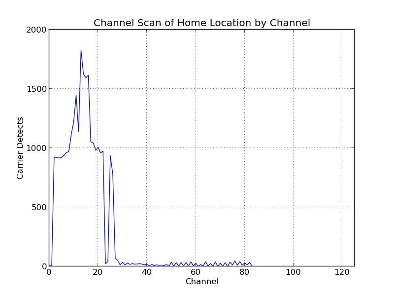
Anyway, I got it working, and then did a scan for a half hour or so to figure out what channels are likely to be free for use. It was pretty apparent that most of the 2.4Ghz activity in my house is concentrated down at the bottom edge of the band even scanning by eye, but I summed up all the carrier detects that it logged during that time, and with a little Python/matplotlib magic:
Oh well, that took me longer than I would like, but I have it working. Next step will be to get one of these NRF24L01+ modules working on a Raspberry Pi. My idea is that all sensors should send information to the Pi, and the Pi will inject it as messages to my MQTT broker for further processing. Then, I can process events with Node Red.
Stay tuned, and hope that I’m not so dumb at every step of the way.