Category Archives: Amateur Science

Simulating a (simplified) Ring Oscillator

Okay, simulating the analog parts of the actual physical ring oscillator last night made me ask some questions, so I thought it might be useful to try a very simple discrete simulation. If you looked at the schematic I posted yesterday, you’ll note that the ring is really just made up of single transistor inverters. The capacitors in combination with the resistors implement a delay line. So, that’s what I decided to code up: a ring of simple inverters, each with a “gate delay” of values which are very close to 1 second. Whenever the input to the inverter is scheduled, the output is swapped to its negation at the time in the future plus its gate delay, which resets the clock of the next gate, and so on. I normally would use a priority queue and the like to keep track of which gate should fire next, but for as few stages as I’m likely to implement, I frankly just search for the gate with the lowest time by linear search, and then proceed. To make the “simulation” a tiny bit more interesting, I print the values of the gates in “pseudo-real” time (I spend it up by a factor of 10). Here’s the code.

[sourcecode lang=”C”]
#include <stdio.h>
#include <stdlib.h>
#include <unistd.h>

#define N 79

unsigned char val[N] ;
double delay[N] ;
double clock[N] ;

#define BIG 1e6

main()
{
int i, idx ;
double t = 0., soonest ;

for (i=0; i<N; i++) {
val[i] = 0 ;
delay[i] = clock[i] = 1.0 + drand48() * 0.01 – 0.005 ;
}

for (;;) {
/* find the inverter that will trip soonest */
idx = 0 ;
soonest = clock[idx] ;

for (i=1; i<N; i++)
if (clock[i] < soonest) {
soonest = clock[i] ;
idx = i ;
}

/* subtract the clock from all the inputs */

for (i=0; i<N; i++)
clock[i] -= soonest ;

t += soonest ;

val[(idx+1)%N] = 1-val[idx] ;
clock[(idx+1)%N] = delay[(idx+1)%N] ;
clock[idx] = BIG ;

usleep(soonest * 1000000. / 10.) ;
for (i=0; i<N; i++)
putchar("_X"[val[i]]) ;
printf("\r") ;
fflush(stdout) ;

}
}
[/sourcecode]

It’s pretty interesting to watch (at least to me). I’ll have more to comment tonight.
Ground tracks of satellite passes…

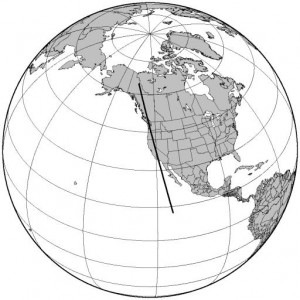
Every once in a while, I feel like making high quality pictures of ground tracks of satellites. The Generic Mapping Toolkit is handy, especially when combined with the pyephem library.

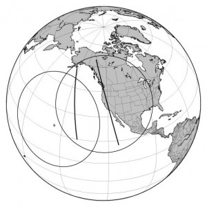
The thick line is the ground track of the amateur satellite AO-51, at any point in its next pass where it is visible from my home location. My idea is to script this up into a generic satellite prediction utility that I can access from my webpage. Stay tuned.

Addendum: I’m particularly interested in passes which might allow me to communicate with Hawaii. Here is a similar map, showing two passes of AO-51 (both passes start from south and move north) and also show the footprints of both San Francisco and Honolulu Hawaii. Any portion of the satellite path which is common to both circles should allow a CA-HI QSO to occur.

Congratulations to SpaceX, and a new Cubesat!

Lost in yesterday’s thrilling launch of the SpaceX Falcon-9/Dragon launch was that during their flight, they also apparently deployed a cubesat: CAERUS (which is apparently Greek for “opportunity”). It has a 900mw FM AFSK beacon downlink on 437.600, and operates under the amateur callsign KJ6FIX. I have not as yet been able to locate TLEs for the satellite, so I’m not sure of its orbit, period and the like, but it might be good to try to give it a listen.

Information Sciences Institute – CAERUS.

Addendum: The Falcon9 also carried a nanosatellite for the Army.

Somewhere… over the (simulated) rainbow revisited…

A couple of months ago, I did some simple simulations of light refracting through raindrops in a hope to understand the details of precisely how rainbows form. The graphs I produced were kind of boring, but they did illustrate a few interesting features of rainbows: namely, the double rainbow, and the formation of Alexander’s band, the region of relatively dark sky between the two arcs.

But the pictures were kind of boring.

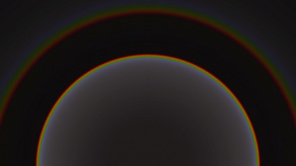
So, today I finally got the simulation working, did a trivial monte carlo simulation tossing fifty million rays or so, and then generated a picture by converting the spectral colors to sRGB. Et voila!

Horribly inefficient really, but satisfying result.

Addendum: In comparing the results to actual photographs of double rainbows, it seems like my pictures are scaled somewhat strangely (the distance between the arcs seems large compared to the radius). I suspect this is mostly due to the linear projection that I used and the very wide field (the field of view of the camera is nearly 100 degrees, which compresses the center and expands the outside. I’ll have to make some narrower field pictures tomorrow when my mind can handle the math, I’ve reached my limit tonight.

Another nifty balloon project…

Luke Gesissbuhler did a balloon launch, lofting an HD video camera and an Apple iPhone to lofty heights before recovering them. Very nice. The footage right after burst was kind of cool: I was wondering whether the fragments of the balloon or parachute tangled with the camera: perhaps dangling the camera on a longer tether could reduce the possibility of them tangling. Still, it all worked out in the end (and rather brilliantly!).

Inspirational.

Homemade Spacecraft from Luke Geissbuhler on Vimeo.

Revisiting: Printing Holograms on a Laser Printer

A few years ago I spent a couple of hours tinkering with implementing Thad Walker’s scheme for printing computer generated holograms (see the link for the paper):

Printing Holograms on a Laser Printer

A recent comment has got me thinking that I should revisit the idea and the paper. For reasons which aren’t entirely clear to me now, it seems that I understand the underlying mathematics much better now (I have done a lot more tinkering with FFTs and the like) and I think that I could use FFTW to implement a much fancier and more robust version of the original program. I also have access to some equipment that might be capable of creating accurate 2400 dpi prints, which wouldn’t hurt. Stay tuned.

Homemade T.E.A. Lasers

Nyle Steiner gets a link from me again, this time for his construction of T.E.A. lasers. I remember reading about these kind of lasers in an issue of Scientific American (I just looked it up, Jun, 1974 in the Amateur Scientist column), but that was the extent of it. Nyle has done a lot of experimentation and written up his notes here.

Homemade T.E.A. Lasers.

These lasers in most respects don’t compare favorably to the ubiquitous laser diodes that we’ve become all-too familiar with, but they don’t require any ability to fabricate semiconductors, blow glass, or indeed, have any machining skills beyond the kind you might have if you can find your way around a Home Depot.

He’s got some YouTube videos about these, oddly enough, that don’t seem to be linked to the above page. Search for his name on YouTube if you want to get more of these:


httpv://www.youtube.com/watch?v=svSUzUBSkD4

Les Météores, René Descartes

I was hoping to find a copy of René Descartes treatment of rainbows as part of Project Gutenberg (hopefully in English) but no dice. It does appear that the Université de Québec has the work Les Météores as part of their online collection. It’s far too late for me to work on reading it (my French is pretty rusty, especially without my French dictionary) but I’ll have to have a look at it some other time.

Les classiques des sciences sociales: René Descartes, Les Météores (1637).

Somewhere… over the (simulated) rainbow…

A few days back, I simulated how light propagated in a single drop of water, but with a number of problems. First of all, it didn’t simulate the Fresnel equations, which describe how light is reflected and refracted at the interface between two media. This meant that in my simple model, no light is actually subject to total internal reflection, and no light was scattered back in the direction that the light originated. This is an important effect: without it, you cannot see rainbows. It also assumed a single index of refraction, so we couldn’t see how the reflection and refraction change as a function of wavelength.

So, I decided to fix both problems, and run a simulation to see if I could capture some interesting features of rainbows by direct simulation.

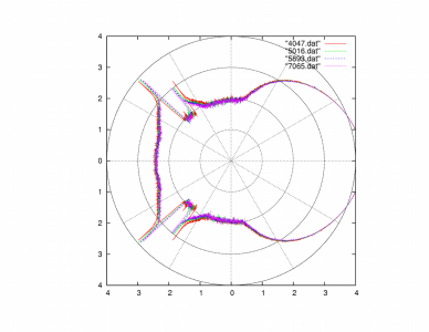
To keep you interested (if possible), I’ll merely give the picture, then explain it. (Click on it to view it full size).

Simulated rainbow reflection, light enters from left, goes to right

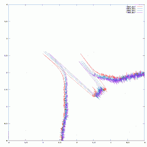
It’s hard to see the detail in the area of interest, so here’s a better version, zoomed in (click to view bigger):

This describes the distribution of light in each outgoing direction, assuming light coming in from the left. There are four different plots, ranging from the shortest wavelength (4047 Angstroms, or deep violet) to the longest (7065 Angstroms, or deep red). (Sadly, there isn’t any correlation between the plot color and the wavelength, you have to look at the legend to interpret things properly.) I got these plots by determining the index of water at each wavelength, and then simulating via Monte Carlo techniques the resulting outgoing distribution by tossing 10 million simulated photons at the drop. At each surface interaction, it determines what the ratio of reflected to refracted light could be, and then take one path or the other based upon a weighted coin flip. The final outgoing directions are binned, and we take the log of the count in each bin to produce the distance from the center in the polar plot.

This plot isn’t the most pretty thing you’ll ever see, but you’ll actually find a number of interesting things. First of all, you’ll see that there are two rainbows represented. The inner one is the brighter, and the outer one is significantly dimmer (you might estimate that it contains 1/10 as much energy, since it appears about 1 unit lower and I used log based 10). The inner bow has violet at the inner side, and red at the outer side while the outer bow is reversed (red on the inner radius and violet on the outer radius). There is also a distinct lack of light between the two bows. The amount of light reflected in between the two bows is less than that scattered outside them. This is a phenomenon called “Alexander’s band”.

I thought this was a fun experiment. I could work a bit harder and actually produce the appropriate colors and intensities by some more computer graphics magic. Perhaps that will wait for some other day.

Khan Academy

I’ve seen the Khan Academy listed a couple of times before, but never really bothered to look at it again until today. I was confused about a minor issue in linear algebra (hey, it’s been 25 years since I took linear algebra) so I surfed over and found the lecture on null subspaces to be clear and easy to follow. The Khan Academy has a huge number of lectures, covering mathematics, economics, physics, and lots of other good stuff. Bookmark it for future reference!

Khan Academy.

Hydropower generator

On hack-a-day today, I saw this interesting link to a small hydroelectric generator. I’ve been interested in DIY/non-centralized generation of electricity for quite a while (without actually developing any serious knowledge about it, mind you) so I found the idea rather interesting. Paul taps water from a stream and uses it to feed a 2 inch water pipe, which eventually gets split into four 1/2 outlets which spray water onto a turbine which drives a low-rpm alternator.

Hydropower generator – Hack a Day.

The hack-a-day article did make one claim which made me pause though: it said it could generate 56VDC at 10A. Really? That’s 560 watts, which seemed a lot. In watching the video, it shows that it can generate 56V (actually AC), but that is without any load. As soon as a load (such as a charge controller) is placed on the circuit the voltage will drop. I’ll work out the math a bit at lunch, but I’d be surprised if you could get much over 100 watts of power. Still, not inconsiderable, and if I had a shack in the woods, it would be a great way to keep the place lit.

It’s also interesting to figure out what the reliability of such a system can be. The turbine is constructed from PVC elbows, and it’s not clear to me how they would handle the stress in continuous duty.

Still, very cool.

On light in drops of water…

A couple of days ago, I linked to an article which talked about using a laser beam as a kind of microscopic projector. The collimated laser light passes into a small drop of water, and then casts the image of protozoa (or other small swimmers) onto the wall. Very cool, but I wasn’t entirely sure what was going on here. The actual physics of the image formation is remarkably complicated, so I thought I’d try to understand it more or less from first principles.

Warning: I could be totally wrong about this stuff. While I have all the right books to figure this stuff out, I haven’t dug them up or consulted them beyond some minor exploration of a couple of formulas.

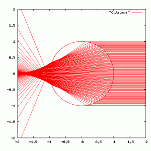
I began by ignoring the wave theory of light entirely (which won’t get us very far, but it’s where I’m starting). What does the distribution of light look like when it is refracted through a spherical drop of water? I looked up the index of refraction for water (around 1.33) and wrote a simple 2D raytracer which uses Snell’s law to trace rays through a sphere. Here’s the result:

A collimated laser beam hitting a spherical drop...

A couple of things to notice: the beam doesn’t converge inside the water droplet: it is “focussed” in a region outside the sphere. It isn’t focused to a single point, it exhibits classic “spherical aberration”: the rays which hit the drop at different vertical positions cross the horizontal axis at different locations. This raytrace also implements what is known as “total internal reflection”: when a ray passes from a dense (say water) medium into a less dense medium, there is a critical angle where instead of refracting, the ray is reflected. It is a rather interesting quirk that this situation doesn’t occur in this hypothetical situation: all the rays hit the far side of the sphere at angles below the critical angle, and therefore exit the sphere after just two air/glass interactions.

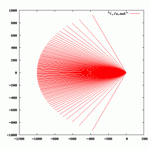
If we zoom far back, we can see what the distributions of light should be:

Same diagram, zoomed way back...

The light is scattered in a smooth lobe out the far side of the laser. In Alan’s photos, you can see a very bright spot, which I suspect is caused largely by the fact that the droplets he was examining where very much smaller than the beamwidth of his laser, and you are simply seeing spillage around the laser light.

I was originally confused because I was thinking there simply had to be rays in this simple setup which would exhibit total internal reflection. My thinking was that rainbows appear opposite the sun in the sky, so there has to be a reflection to get light back into your eye. But the mechanism of this propagation isn’t by total internal reflection, it is governed by the Fresnel equations. Whenever light passes between two media which have differing refractive indices, both reflection and refraction may occur. The critical angle of Snell’s law is simply a subset of the behavior described by the Fresnel equations. Fresnel’s equations predict the reflectance and transmission at interfaces based upon the angles and media. Using this, you can determine that even at angles which are normal to the surface, you get some reflectance (in the case of air/water, about 2% of the light is bounced back). It is this Fresnel reflectance on the interior bounces which is apparently responsible for the appearance of rainbows.

(Of course, rainbows rely on the fact that the refractive index of a material is wavelength dependent. Our laser is essentially a single wavelength, so we won’t ponder it further now).

Anyway, back to the laser projector. It was apparent to me from the original video that there were significant diffraction patterns around each Protozoa, and Alan’s video (with much smaller critters) is primarilly full of diffraction patterns. It is my believe that most of the light passing through these drops is actually propagating via diffraction (much like Gabor’s inline holograms) rather than simple projection. The laser beam doesn’t form a small point inside the droplet, it is much closer to being a single collimated beam. This means that potentially the methods used for digital inline holography could be applied to this very simple experimental setup.

More thoughts on this as they occur.

Basics-Picavet – Kite Aerial Photography Electronic Resources

I might have an opportunity in a couple of weeks to go do some kite flying at an upcoming picnic, and I thought that I might give a quick try at quick and dirty kite photography. After all, I’ve been musing about lofting a camera up high using a weather balloon, so why not start with elevations of just a few hundred feet? I haven’t given this much study or thought, but I know that designing an appropriate rig for attaching the camera to the line is a key element. My idea is to loft my old Canon SD1100 on a little gadget which is known as (I had to look it up) a Picavet. It’s a fiendishly simple and clever device for keeping the camera basically level while attached to the kite string. Check it out:

Basics-Picavet – Kite Aerial Photography Electronic Resources – KAPER

I’ll probably tack this together sometime next week after a quick trip to the hardware store. Stay tuned for pictures.