Category Archives: Arts and Crafts

Puppet Making, and Mathematics…

I’ve been taking a puppet making class, and I must admit, it’s been a lot of fun. Too much fun, in fact. I’ve been thinking about puppet making, watching puppet making videos, and scouring the web for inspiration and guidance.

To date, I’ve only completed one puppet (his name is Gerfil, and he may still acquire eyes), so I have a lot to learn, but it’s fascinating.

Gerfil is a pretty ordinary hand puppet, but has a shape which is more refined than many of the simple arts and crafts patterns you can see on line. But I got fascinated by the process of pattern making. Digging around, I discovered this nifty video.

I rather liked the spherical head, but thought that it was a little odd that he disassembled a baseball cap to generate the pattern. The mathematician in me thought that it must be possible to generate a similar pattern using, well, mathematics. I began by considering a couple of basic design criteria. The top of the head would be a hemisphere, divided into six identical gussets. I decided to settle on an eight inch diameter head, which means that the total circumference is about 25 1/8 inches around. Since all six gussets are identical, it makes the base of each triangular gusset a little over 4 inches across the base. I set the height to be the circumference divided by four, or a little over six inches. But then the question became how to draw the curve connecting the base to the apex of this triangle.

I decided to test a few ideas, and then print them out on paper to see how well they worked. I suspect that the ideas I used to generate this pattern are simply not quite right, but they aren’t hugely off. The sides are defined by a simple quadratic bezier, set to establish the tangent at the base to be a right angle, and the apex of the triangle to have a sixty degree angle.

The result looked like:

sector

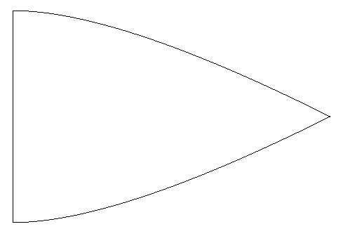
Cutting them out, and taping them together resulted in this:

photo (4)

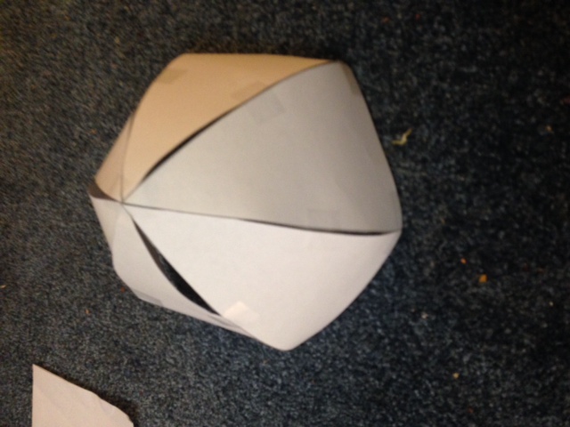
It’s not bad, but it’s not great either. I suspect that if it was rendered in foam, it would be a bit better, as the foam is both compressible and stretchable. I suspect that to really do the job right, I’d need to simulate that more directly, and use real optimization techniques. But I did this while watching the Oscars (I’ve got 11 right so far) which means I can’t concentrate enough to pull off harder math. I’ll think about it more and try again in the next few days.

Addendum: Here’s a nice puppet pattern with some construction tips.

Christmas Lights powered by an ATtiny13

While waiting for my bread to rise the other day, I moved my breadboard ATtiny13 circuit that blinked two leds to a small Radio Shack perfboard, added a couple of switching transistors (2N3904s) to power the LEDs, and built a small 7805 regulator (which doesn’t yet have any filter caps, I’ll get to that). But, I couldn’t resist powering it on. And after finding a small solder bridge (a hairlike strand that spattered and connected two of the microcontroller pins), it worked!

Hopefully this stuff will get mounted in a hat this weekend. Stay tuned for the final video.

Addendum: I received one request for the source code. It’s trivial. Here you go.

[sourcecode lang=”cpp”]
#define F_CPU 1200000UL

#include <avr/io.h>
#include <util/delay.h>

/*
* xmas.c
*
* A small program for the ATtiny13 that can control two strands of
* Christmas lights. I found a set of batter powered LED Christmas
* lights at CVS on sale for $.99 each. I took the lights out, and
* found that they consisted of two strands: one of 4 red and 4 yellow
* LEDs, and the other of 4 blue and 3 green LEDS. Each strand is
* wired in parallel and draws about 20ma at 3 volts. I have a few
* ATtiny13’s lying around, which can use between 2.7 and 5.5 volts supply.
* I think for this test, I’ll wire up a little 7805 regulator to provide
* 5V, and then control each strand with one of the two PWM outputs.
* If I want to drive the strings directly from the microcontroller,
* I’ll have to insert another 50 ohms of resistance to limit the current
* to around 20ma per pin. I could also add a 1K resistor and a small
* NPN transistor to drive each pin at the higher voltage. At 5V, the
* strand will draw about 120ma.
*/

#define LED0 PB0 /* pin 5 on the ATtiny13 */
#define LED1 PB1 /* pin 6 on the ATtiny13 */
#define SWITCH PB4 /* pin 3 on the ATtiny13 */

int brite, dir ;

int swd = 0 ;
int swu = 0 ;

int
main(void)
{
DDRB |= (1 << LED0) ; /* set both LEDs as outputs */
DDRB |= (1 << LED1) ;
DDRB &= ~(1 << SWITCH) ; /* and the switch as an input */
PORTB |= (1 << SWITCH) ; /* and activate the internal pull up */

/* This configures the PWM outputs to be in "Fast PWM" mode. */
TCCR0A |= (1 << WGM01) | (1 << WGM00) ;

/* Timer is clocked at F_CPU/8 */
TCCR0B |= (1 << CS01) ;

/* COM01 COM00
* 0 0 | normal port operation, output compare disconnected
* 0 1 | toggle output on compare match
* 1 0 | clear output on compare match
* 1 1 | set output on compare match
*/

TCCR0A |= ((1 << COM0A1)) ;
TCCR0A |= ((1 << COM0B1)) ;
OCR0A = 0;
OCR0B = 0;

for (;;) {
/* SOLID ON */
for (;;) {
OCR0A = 0xff ;
OCR0B = 0xff ;
_delay_ms(1) ;
if ((PINB & (1<<SWITCH)) == 0)
break ;
}
while ((PINB & (1<<SWITCH)) == 0) ;

/* CROSS FADE */
brite = 0 ;
dir = 1 ;
for (;;) {
OCR0A = brite ;
OCR0B = brite ^ 0xFF ;
brite += dir ;
if (brite == 0 || brite == 255)
dir = -dir ;
_delay_ms(2) ;
if ((PINB & (1<<SWITCH)) == 0)
break ;
}
while ((PINB & (1<<SWITCH)) == 0) ;

/* BLINK */
brite = 0xff ;
for (;;) {
OCR0A = brite ;
OCR0B = brite ;
_delay_ms(500) ;
brite ^= 0xff ;
if ((PINB & (1<<SWITCH)) == 0)
break ;
}
while ((PINB & (1<<SWITCH)) == 0) ;

/* CROSS BLINK */
for (;;) {
OCR0A = 0xff ;
OCR0B = 0 ;
_delay_ms(500) ;
if ((PINB & (1<<SWITCH)) == 0)
break ;
OCR0A = 0 ;
OCR0B = 0xff ;
_delay_ms(500) ;
if ((PINB & (1<<SWITCH)) == 0)
break ;
}
while ((PINB & (1<<SWITCH)) == 0) ;

}
}
[/sourcecode]

Dissecting a set of $.99 battery powered Christmas lights…

I was over at the CVS repository today, and saw that they had some small strings of fifteen LED Christmas lights on sale for a paltry $.99 (if you used your CVS discount card). That was simply too much to resist, so I got a couple of strings, and thought that I would use them for a Christmas related electronics project of some sort.

And, of course, it provides a reason to test your basic electronics knowledge as well. (Forgive my more technologically saavy readers, this is gonna be pretty basic, but I found it fun to go through the mental exercise).

First of all, here are photos of the box they came in, just so we are all on the same page:

When you pop them open, you’ll find a small greenish plastic box that holds the batteries, and a string of fifteen LEDs wired into it with green wire. The box has a small switch on it, which if you stare at you’ll see has both an OFF and an ON position, but it can also be set half way to enable a blinking function. Popping two batteries into the case and flipping the switch had the desired effect: Christmas lights!

So, I started staring at them. There are three wires coming out of the battery box. Each LED appears to have five wires operating in its vicinity. One bypasses the LED, and four other wires sprout from each LED (except for the very last one on the string, which just has two connections. A few minutes of thinking reveals that the LEDS must be wired in parallel, with a circuit that looks very much like this:

Ed. note: Mike pointed out that the original schematic was in error. This has been updated.

The lines labelled A and B are just two power lines: each carries power to half of the LEDs. In the “blink” mode, power is applied to only half of the LEDs at a time. Staring inside the box, it appears that there are two discrete plastic cased transistors wired together: my guess is that they are a classic multivibrator circuit. I’ll verify that later.

Okay, enough of boring reality, let’s try to get to the exciting math.

First of all, the package says that we can get “120 hours or more” from one (presumably) set of alkaline batteries. That seems like excellent battery life, but how realistic is it?

First of all, how much power is in a pair of AA alkalines? Wikipedia says we have about 1800-2600 mAh. I bought some cheap AAs from CVS, so let’s say we are in the middle of the range, about 2200 mAh. Naively, to last 120 hours, the current draw can only be 2200 / 120 or about 18ma (this isn’t quite right, but it’s close) which works out to about 1.2 ma of current per LED (did I mention that the LEDs are wired in parallel?). The total power consumed is about 50mw. If we assume the voltage drop from the LEDs is around 2 volts, we need we need to have a series resistance of about 1 v / 18ma or about 55 ohms. It can be a tiny one, since the power consumed is very small.

All this presumes that they were all in parallel. In reality only half the current flows in each of the A and B circuits, so in blink mode, I suspect the power consumed will be cut by one half (ignoring the power consumed by the multivibrator, which should be very low).

But here’s the good thing! The current draw is low enough that it should be possible to power these lights directly from an Arduino, without any additional switching transistors or the like. My intention is to power each of the two strands with a PWM signal, to allow independent fading and glowing.

But I don’t trust my math enough (nor the specified 120 hour life) to just hook this up randomly, so I’ll be doing a little dissection when I get home tonight, to verify that my calculations are roughly correct. Stay tuned!

Addendum: I took a closer look at the tiny circuit board inside the battery case, and was somewhat surprised to see its inner workings hidden under a blob of epoxy. Two driver transistors do appear on the top side. As far as I can tell, no caps or inductors are visible anywhere:

Addendum2: Last night I put my multimeter in series with the batteries in this circuit, and measured a current draw of 40 milliamps in its “steady”, non-blinking mode. That means that the 120 hours on two AAs quoted on the box is likely a fiction, a life of more like 55 hours would seem to be more likely. In blinking mode, the current draw seemed to vary between 20ma and 30ma, but my meter wasn’t able to integrate the current to a stable value.

I’m thinking that I’ll resurrect the circuit that I used for my ATtiny13 powered pumpkin to drive these LEDs. The ATtiny13 has two PWM channels, which could be used to drive the two LED channels separately, allowing some cool color fading effects. I could probably even salvage the case to hold the batteries. Stay tuned.

HOPALONG, from Dewdney’s Armchair Universe

All this fiddling around with the Lorenz attractor has made me try to think of other simple, easy graphics hacks that I could make. I recalled that A.K. Dewdney had some simple graphics hacks in one of his Computer Recreations column back in the 1980s. It turns out that Wallpaper for the mind was published back the September 1986 issue of Scientific American, and was reprinted in Dewdney’s compendium The Armchair Universe. I had a quick look, and wrote the following implementation of the HOPALONG program first… discovered? written? by Barry Martin. The program initializes X and Y to zero, and then repeatedly applies a pair of functions to the existing X, Y to generate new values. The program here just prints the values.

[sourcecode lang=”C”]
#include <stdio.h>
#include <stdlib.h>
#include <math.h>

#define LIMIT 21000000

double sgn(double x)
{
if (x == 0.) return x ;
if (x < 0.0) return -1. ;
return 1.0 ;
}

main(int argc, char *argv[])
{
double x, y ;
// double a = -200, b = .1, c = -80 ;
// double a = 0.4, b = 1, c = 0 ;
// double a = -3.14, b = 0.3, c = 0.3 ;
double a = -1000., b = 0.1, c = -10 ;
double nx, ny ;
int i ;

x = y = 0.0 ;

for (i=0; i<LIMIT; i++) {
printf("%lf %lf\n", x, y) ;
nx = y – sgn(x) * sqrt(fabs(b*x-c)) ;
ny = a – x ;
x = nx ;
y = ny ;
}
}
[/sourcecode]

Depending on the value of a, b, and c, a different set of points is produced. I’ve left several “interesting” values as comments in the code. The set that remains uncommented is actually among the more interesting. It generates all sorts of interesting details. To visualize these points, I found it convenient to use gnuplot. Zooming into a fairly small region, you can see this wonderfully vascular like pattern evolve:

I remember implementing this on my old Atari 400 back then. But I probably didn’t really appreciate how it worked. Now, I recognize that this iteration is some kind of iterated function system, and that you might reasonably expect it to develop these kind of fractal patterns. It seems likely for convergence that the variable b should have absolute value less than 1, but a and c can (I think) be more or less chosen at any scale you desire. The sqrt implements some nonlinearity, which accounts for the many curved features that are visible.

This program has all sorts of fun tweaks. It always begins by initializing x and y to zero, but if you try different starting points, you get different orbits. You could try coloring the dots by slowly changing the way they are colored, or by coloring all points on the same orbit the same color. I removed the sqrt, and still got some interesting patterns. I’ve also thought of producing some animations by slowly varing some of the parameters to see how the resulting pattern evolves. All sorts of good stuff.

Weird Sound Generator

Here’s a link for Tom: a kit for the Weird Sound Generator. Unlike many of these things, I actually found the variety and quality of sounds produced by this thing to actually be pretty darned interesting. It might be fun to build one of these and work on your own soundtrack for Return to the Forbidden Planet. Check it out:

Weird Sound Generator

Here’s an MP3 of the example sounds you can make with this gadget.

Gutenberg Gem: Animal Children by Edith Brown Kirkwood

Cute Squirrel

Want some cute animal pictures?  Try checking out this minor gem: Animal Children by Edith Brown Kirkwood from Project Gutenberg.   It’s got lots of really strange pictures that look like conventional animal pictures cut up and then clothing drawn around them.  Strange stuff, but oddly kind of fun too, might be fun for a kid’s craft project, and heck: they are in the public domain.

[tags]Cute Clip Art,Project Gutenberg[/tags]

Aztec + Lego

It’s a strange fact that any two words (or interests) that you might have will eventually find a webpage that illustrates them both.  Of course, every geek in the universe likes Legos, and a couple of years back I made an aborted stab at learning something about Mayan hieroglyphics.   I didn’t think I’d find a webpage that harmonizes the two, but check out Dunechaser’s Blocklog for his Aztec Minifigs.

Addendum:  Wikipedia on Mayan hieroglyphics, PDF of Introduction to Maya Hieroglyphs by Kuttunet and Helmke, or How to Read Maya Hieroglyphs by John Montgomery.

[tags]Maya,Lego[/tags]