My recent experiments with light based communication left me thinking about simple circuits for driving LEDs. I’ve got three big LEDs (1W) on order from deal extreme, so I was looking for circuits to drive these larger LEDs. This Instructable has some good ideas. I’ll probably breadboard some of these soon.
Category Archives: electronics
Question about LEDs…
A few days ago, I posted a query to twitter regarding voltage drop in LEDs:
I didn’t receive a lot of truly helpful replies: a few people reinforced the general dogma that indeed LEDs were diodes, and since they were diodes, they should have relatively constant voltage drop despite current across them. But that’s not what I am observing with my simulations using LTSpice.
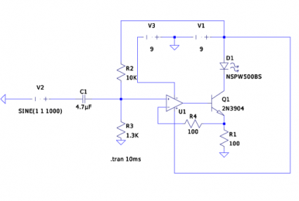
Here’s the schematic for my linear current based LED modulator more or less as I built it (for some reason the circles which define the voltage sources V1 and V3, as well as the simulated input signal V1 don’t show up, sorry ’bout that). The basic idea though is that the voltage appearing at the noninverting input of U1 is a 1V peak-to-peak audio signal, offset by 1 volt so the total range is 0 to 2V. The action of the op amp ensures that the voltage appearing at the top of R1 is the same as the noninverting input. Since the load is a constant resistance, that means the current is proportional to the voltage, and varies exactly with variations in the input voltage.
So, what are the voltage drops across the LED (D1) and the transistor (Q1)? My intuition says that the voltage drop across the LED should be (as per conventional wisdom) nearly constant. Looking at the datasheet for the NSPW500BS (a white LED manufactured by Nichia) I see that it lists a typical forward voltage of 3.6 volts (I picked it at random from the list of available LED models in LTSpice). So, what I would expect would be that the voltage drop across D1 would be nearly constant at 3.6 volts, and since the voltage drop across the load resistor mimics the input signal, that the drop across Q1 would look like 9V minus the audio voltage minus 3.6 volts.
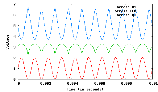
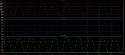
But here’s what LTSpice produces:
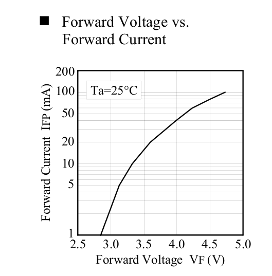
You can see that the voltage across D1 varies by nearly a volt. I tried replacing D1 with a more conventional diode (such as as a 1N4148) and the variation is much smaller (maybe 0.1V). Digging into the datasheet for the LED, I found this diagram:
Which does seem to imply that over currents of (say) one to twenty milliamps, the forward voltage drop may be a volt (and more, if you push more current through them).
So, here’s my question: is that typical of LEDs? Or maybe just white LEDs? And the more broad question: how can I translate information from the datasheet of an LED into a usable model for LTSpice so that I can realistically model this behavior?
More light transmitter experimentation…
 Today, I had to do some yardwork, so I dusted off the weed whacker, and climbed the back of the hill to chop down some high grass. At the end of an hour, I was about 40% done (I’ll do the rest next weekend) but sneezing and coughing from the liberated pollen and dust. So, I called it a day, made a mental note to get a dust mask for next week, and showered.
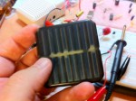
But while I was chopping grass, I located an old solar powered LED light that had been lost among the tall grass. It was probably three or four years old, and covered in dirt and dust. The solar cell in particular looked like some water had gotten in it.
The perfect organ donor for an improved receiver for my LED transmitter, thought I.
And it is. I disassembled the light, snipped the LED panel out, and soldered it in place of the LED that I was using in place of my receiver previously. And, not surprisingly, it works better. A lot better! A lot louder. Over a greater distance. There is no real contest.
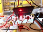 I tried to shoot some video of it, but my hands are simply too shakey (muscles twitching from operating vibrating machinery for an hour) and it’s unwatchable. But here’s a little MP3 file that will perhaps hint at some of the improvement.
Demonstration of solar cell as light receiver (MP3)
Addendum: I decided to go ahead and post some video. It’s still pretty shaky, but it’s a reasonable demonstration of what’s possible with a scavenged solar cell. Pardon for the relatively poor lighting: my office is lit by compact flourescent bulbs, and when they were all on, the 60 hz whine (which you can still hear despite lowering the light levels) was pretty irritating.
Improved Joule Thief Circuit
While surfing for more LED information, I found this rather nifty little circuit on Electronic Design’s website. It’s a little Joule Thief-like circuit, but with enhanced efficiency (~80%) and it can drive white LEDs with rather large forward voltage drops. Archived for later….
DIY FET/home-made transistor Scientific American June 1970
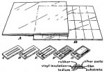 When I was still in grade school, I (and this will be a shock to my readers) spent a lot of time in libraries. Our library used to have a free bin, where they would toss things that they no longer wanted in their collection. One day, I came by and found a pile of more than two decades of Scientific American magazines. Being a bit of a science nut, I carted them home, and spent many a happy evening reading Martin Gardner’s Mathematical Games and C.L. Stong’s Amateur Scientist column. Stong’s column was really cool, and had great articles about building plasma jets, X-ray machines, diffraction ruling machines, and all sorts of other good stuff.
It was then with some suprise that I read Nyle Steiner’s article on making FET transistors from cadmium sulfide photocells, because he made reference to a 1970 article by Roger Baker that was about making home made FET transistors. I didn’t remember any such article. Luckily, I bought a CDROM which contains all the Amateur Scientist columns, and found it. And, indeed: it’s the second half of a two part column, and talks about the deposition of thin films. I guess I had never read it closely enough to see that it included the manufacture of a thin film transistor.
Here is a link to an online copy of the article.
The article also makes reference to THIN FILM MICROELECTRONICS: THE PREPARATION AND PROPERTIES OF COMPONENTS AND CIRCUIT ARRAYS which was available in preview mode on Google Books, and it seemed enticing enough that I decided to track down a copy via online search (I managed to find a copy for only $6 + $3.50 shipping). It seems like the level of this book might be within the reach of the dedicated amateur.
Good stuff.
LED Transmitter Schematic
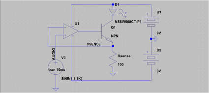
Okay, so here’s the schematic for the LED transmitter circuit as I assembled this evening. I tried to write up an exposition of how it works, but frankly, it pales in comparison to the clarity and completeness of KA7OEI’s page. But here’s the basic idea: imagine that you supplied 1V to the input of the op amp. The op amp will drive the voltage at the base of the transistor so the voltage coming off the Rsense is the same (1V). When that happens, the current through Rsense (and through D1) is just 1V/100 ohms (in this case) or 10ma. And, the current is linear in the input voltage: when the voltage rises to 2V, the current is 20ma, and when the voltage drops to zero, the current is zero. So all you really need to do is take a 1V peak-to-peak audio signal, offset it by 1V (which I didn’t show on the schematic, it’s just inside the audio source node), and it will generate the appropriate current.
It’s very cool, and requires very little math to actually design. And it doesn’t matter much what the transistor is either: KA7OEI’s page uses a power MOSFET, because he is driving a much more powerful LED, but for my purposes, using an ordinary 2N3904 worked just fine.
An improved linear current LED transmitter
I spent some time reading KA7OEI’s great article on creating a good linear current driver for an LED or laser based communication system. The basic idea was pretty straightforward, so I decided to try it out when I got home. The “simple” circuit that I had before was in no sense linear: the audio became severely clipped by the action of the LED. KA7OEI shows how you can use an operational amplifier to provide a linear current source. I’ll draw up the schematic in the next few days, but if you read his pages, you’ll probably find it easy to figure out.
YouTube – An improved linear current LED transmitter.
KA7OEI – LED Linear Current Modulator
My silly experiment with an LED communicator naturally led me to looking up more complex (and better engineered) versions of the same kind of circuit. There are now cheap LEDs that can emit a watt or more of energy, and produce a prodigious amount of light. It seems like an area which is ripe for amateur experimentation (and just general mucking around) and could leverage some of my optical design skills as well. KA7OEI has some really good ideas and circuits for driving these kind of LEDs with as little distortion as possible, and will be definitely worth looking at:
A simple LED transmitter, and LED receiver!
Tonight’s 20 minute electronics project was to create a simple transmitter to send music using light. A trivial circuit modulates the current through an LED, and a different LED serves as an (inefficient, and not very good) light sensor. Normally you’d use a selenium photocell or the like, but I couldn’t find one in my junk box, and Radio Shack doesn’t have ’em anymore. But LEDs will generate a small current when exposed to light, so you can actually use them as a photodetector.
Addendum: The audio in the video above is pretty weak (the microphone on the iphone is located at the bottom of the phone, and isn’t ideal for recording low level audio). So, I went ahead and recorded a small sample using the voice memo application on the iPhone, and holding the microphone much closer to the speaker of the amplified speaker to give you a better idea of what the quality is. I also reduced the value of the input filter cap to just 4.7uF, which seemed a bit better, and also put in another 4.7uF cap in series with the sensor LED. I’m not sure that helped, but the levels and sensitivity seemed better. At the very least you should be able to hear the audio quality more clearly.
Audio from my LED Transmitter/Receiver (MP3)
Addendum2: The guys over at the Make Blog had some more good information about using LEDs as light sensors.
All LEDs are not created equal…
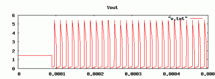
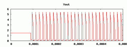
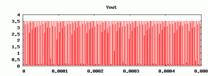
Of course I knew that all LEDs aren’t the same: they differ in color, size and brightness. They also differ in the forward voltage, reverse voltage and capacitance. When I simulated the Joule Thief with LTSpice, I just picked a random LED out of LTSpice’s catalog. When I simulated it, I got a waveform like this:
The voltage peaked over 5 volts, and the frequency was around 64khz.
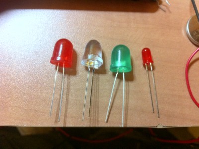
But what does the waveform really look like? I grabbed four LEDs out of my junkbox for testing, found a battery holder so I wouldn’t have to use three hands to get it hooked to my oscilloscope, and shot some pictures. First, the LEDS:
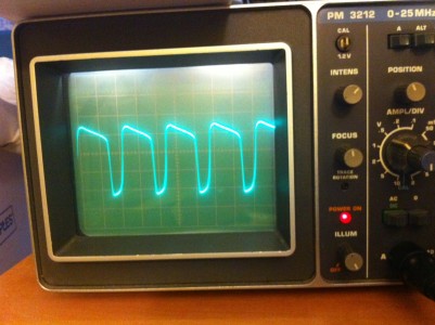
From left to right, they are a generic large red LED which used to be part of a throwie, a high-intensity lensed red LED from Radio Shack, a large green LED from radio shack, and a smaller common red LED from my junk box. I hooked them each up to the joule thief in turn. They all lit up. Here’s the generic red large LED:
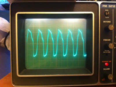
The cycle time is a bit faster than I predicted: I estimate it’s oscillating at around 200khz. It’s voltage peaks are also quite a bit smoother and lower than the model I set up in LTSpice. For this picture, the vertical markings are just 0.5 volts, indicating a peak to valley of about 2 volts.
Here’s the larger, high intensity LED:
It’s much closer to a sine wave, and with a much higher peak to valley.
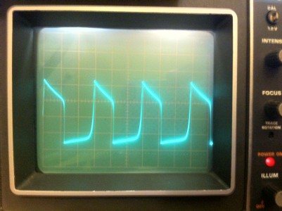
Here’s the green LED:
Much more trapezoidal, but with a catch: the voltage variations were so great I had to change the oscilloscope settings to 1 volt per vertical division.
And finally, here’s a smaller, run of the mill red LED…
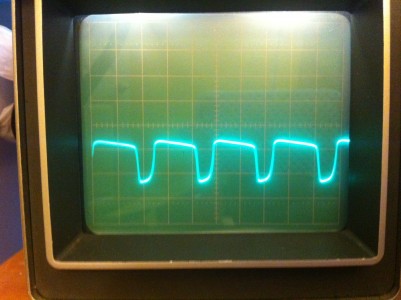
I left it at 0.5 volts per division, so you can see this is much lower.
So, what have I learned from all this? Well, not much at the moment. The green LED seems to match the waveform that I got from simulation most closely, but it’s oscillating at a higher frequency than predicted, and still has a somewhat lower peak to valley voltage range. I’ll probably go back and tinker with the LTSpice model some more (probably by modifying the characteristics of the diode, as well as varying the inductance of the transformer) and see if I can capture the variety of waveforms that I see here.
It was a fun excuse to hook up the scope.
Inductive Spikes: Simulation and Reality
Kindred spirits Atdiy and whisk0r over at the tymkrs blog were playing around with inductors:
They demonstrated that inductors can generative large inductive spikes: in spite of the fact that there coil is charged by a relatively low voltage, when you sharply disconnect a coil from a charging voltage, it generates a large voltage spike that can be measured (by a volt meter) and also generates a visible spark.
I thought it would be fun to see if I could simulate this using LTSpice. I wanted to make sure I understood what was going on, and try to see if I could get some measure of what voltages could actually be generated.
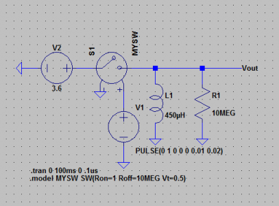
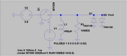
Here’s the schematic I came up with in LTSpice:
It’s a pretty simple schematic really. It’s got an inductor L1, that is about 450uH of inductance (calculated with an online calculator from rough measurements that Atdiy supplied me). The resistor in parallel is 10 megohm, which is similar to the impedance of a typical volt meter. I then have a voltage controlled switch, powered by a square wave. Whenever the input voltage goes greater than 0.5 volts, the switch connects, presenting a resistance of merely 1 ohm. When it drops below 0.5 volts, it presents a resistance of 10 megohms. The inductor is charged by a nominal 3.6 volt battery.
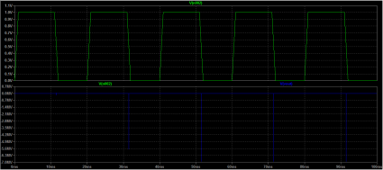
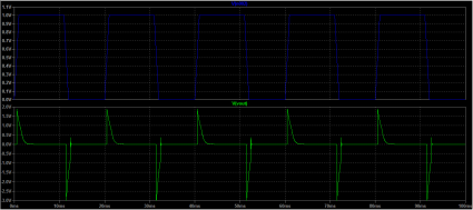
So, what does it look like when you simulate it?
Across the top, you can see the voltage that gets applied to the voltage controlled switch. Across the back, you see large negative spikes in voltage. Really large. We see spikes of nearly 7 megavolts. Pretty amazing, from a 3.6 volt supply! This simulation may be overly optimistic: after all, it doesn’t take into account the stray resistance and capacitance that are likely to be present. But clearly Atdiy’s real life test indicates that high voltages are being developed.
In real life applications where inductive loads might be connected and disconnected quickly to varying loads, it’s common to use diodes to protect the remaining circuit from these high voltage spikes. We can do that in our simulated circuits too. Let’s add a pair of diodes to shunt both positive and negative voltages to zero (I picked 1N4158 diodes, somewhat arbitrarily):
They do their job, check out the voltages:
Neat!
Magnetic core memory reborn… on an Arduino????
I may have mentioned before, I’m kind of old. One measure of how old I am is the fact that I’ve actually programmed machines that used core memory. Real core memory. Little ferrite donuts on arrays of wires.
Some time ago, I remember running across this awesome blog post from “Wayne’s Tinkering Page” which showed some experimentation in creating a driver for some surplus 1mm ferrite memory cores, effectively creating a single bit memory. I thought that was pretty darned cool. But what’s even more amazing is what Ben North and Oliver Nash have done: create a 32 bit core memory shield for an Arduino.
Links to the report and board plans, bill of materials and software
And they have an excellent report on the project, which includes a reference to a different core memory technique which employed non-destructive reads.
Very cool.
Simulating the Joule Thief with LTSpice
I always think it is good to follow up a practical build of an electronic circuit with some simulation to try to learn some of the underlying design principles. LTSpice is a great circuit capture/simulation system which runs on Windows, but also runs pretty well under Wine. I was a bit intrigued by the behavior I noticed in my video: while the LED lit quite well using a single AA battery with a nominal 1.5 volts, when I connected the circuit to an old, partially depleted lithium coin cell that I extracted from a burned out “throwie”, it did not light my LED despite being measured at a nominal 1.4v or so. I thought this was pretty interesting. I had an idea about what the problem was, so I thought I’d test it in LTSpice.
Warning: I don’t know what I’m doing. That’s why I am doing what I am doing.
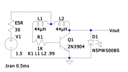
Here’s the schematic that I entered:
I determined the value of the inductors (44uH) using an online toroid calculator, specifying an FT-50-43 toroid with 10 turns through it. The K1 statement creates a transformer out of L1 and L2, with a coupling coefficient of 0.99 (just a guess, they are wound on the same toroid, I expect it to work rather well). In the circuit as presented, the battery is represented by the voltage source V1 and the resistor labelled ESR. From a data sheet for EverReady AA batteries, I found that the typical series resistance is somewhere between 150 and 300 milliohms. I picked an LED out of LTSpice’s catalog: no attempt was made to ensure it was close to the random LED I grabbed from my junkbox.
If you simulate it for a half a millisecond, and look at the voltage at Vout, you get the following graph:
If you change the ESR to 30 ohms, and look at the voltage
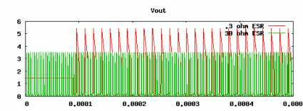
Here’s a graph comparing them:
We can see that the voltage going into the LED peaks much higher, and remains higher for a significant period longer when supplied with a battery with a lower ESR. Using the FFT function, we can determine that the fundamental frequency is around 64Kh, and we can see that the average current is around 35 ma (a bit higher than the recommended average power for the LED, but not tremendously high, given the high frequency at which it operates).
When we have a 30 ohm resistance, the average current through the LED drops to a mere 3.5ma. While the voltage does appear to peak higher than the forward voltage needed to light the LED, the current supplied is simply too short and too low to significantly light the LED.
This seems to verify my experiments to a degree. But last night, I thought of this, and thought that perhaps I could boost the ability of these coin cells by paralleling them with a capacitor. I yanked out an electrolytic of around 220uF from my junk box, and wired it in parallel with the coin cell. The LED did light, but at a very low frequency, just a couple of Hertz. If I add a similar cap to my simulation, I don’t get this behavior. Not sure what’s going on. Any real engineers in the audience care to school me onwhy what I did here is completely inaccurate/wrong/stupid?
The Joule Thief — Lighting an LED with 1.5 volts
I was bored, but not quite up to the challenge of debugging my existing radio project, or starting a new one. I idly began winding some wire onto a FT-37-43 toroid, and then remembered that I had never constructed a “Joule Thief”, a simple little circuit that allows you to light an LED using just a 1.5 volt cell.
YouTube – The Joule Thief — Lighting an LED with 1.5 volts.
Addendum: I mentioned that legendary hacker Jeri Ellsworth had mentioned this circuit in one of her videos: I dug around and found the video. Her circuit is nearly identical, but adds a few components to implement a simple charging circuit.
I also did some experimentation with LTSpice to figure out why the lithium coin cells I scrounged from our old “throwies” didn’t light the circuit, even though they still measured 1.5v. It appears that these coin cells might have significant series resistance (perhaps as much as 30 ohms) compared to the much lower value for alkaline batteries (a nominal 150 to 300 milliohms, according to one datasheet I found). This appears to keep the transistor from supplying sufficient current to switch. I experimented with placing a capacitor across the coin cell (various values, from 33uF to 220uF electrolytics) and found that this did cause the LEDs to blink, but at a very low rate (with a 220uF, about 1Hz). I’ll try to follow up this post with one showing LTSpice and its simulation.
A small standalone homebrew computer: FIGnition by Libby8dev
I’m old. I learned to program as a teenager in the 1980s. Back then, we learned to program on small microcomputers. These machines weren’t very powerful, but they had a neat feature: they were self-hosted. In recent years, a large variety of small microcontrollers have become popular. Many of these have capabilities far in excess of what we had back then, but almost without fail the programming environments they use are hosted on much more powerful machines, often using code which measures tens or hundreds of megabytes.
That has always seemed a bit excessive to me, particularly since making the environments simple and self-hosted pays benefits for educational and hobbyist applications.
The FIGnition board is a project which seems to combat this trend:
FIGnition is an educational DIY computer, based around an Atmel AVR microcontroller. It uses 3 chips and only 46 components to provide a complete self-hosted computer with 8Kb of RAM; 384Kb of storage space; an 8-key keypad and PAL video output. It is interfaced and powered by USB and uses V-USB to provide firmware upgrades by implementing a usbasp device. It runs a variant of FIG-Forth.
Currently it isn’t available in the US since it doesn’t do NTSC video, but I suspect that will change soon. I’ll be looking back at this project periodically.

