Category Archives: Hardware

An inexpensive, open source, two factor authentication USB token: the U2F Zero

If you are like me, you have lots of accounts, and lots of passwords.   Keeping track of them all is a bit of a pain, and it’s increasingly something that you just can’t do with your brain. Several of my accounts now refuse to allow you to use a password which I consider manageable for memorization. Even if I could memorize them, you can’t reuse them for multiple accounts, so each new account places additional labor. This means that you often forget passwords, that you often have to reset them (which is a pain) and which is no real panacea for security, since if someone has access to the device or email that you receive reset notices about, they can go ahead and change them as well.

I’ve no original thinking about this: simply google “problem with passwords” and you’ll get dozens of articles about issues surrounding password security.

Most places are no ameliorating some of the worst problems with two factor authentication. The idea is that in addition to knowing the login password, you need to do something else, such as provide a separate time based, one time password generated by your mobile phone. Perhaps the most widely used of these is Google Authenticator which is an application that can be run on your phone. Many mobile applications such as Google Mail, Facebook, and WordPress can be configured to use Google Authenticator.

And it’s not a bad solution. In fact, it’s the solution that I used on my blog and many other applications for quite some time.

But it is kind of a pain. When you log in you have to stop what you are doing, dig out your phone, and then select the account you are interested in, and then manually copy the number from the app to your website or whatever. I began to wonder if there was some other sort of two factor authentication that would be simpler.

Recent models of the iPhone and MacBook have fingerprint scanners builtin. In many situations to verify your identity, you just press your thumb onto the pad, and voila. It’s very convenient.

But I wanted a simpler solution for use on my laptop, which doesn’t have a fingerprint scanner.

Enter the U2F Zero, a $9 USB fob you can order from Amazon.

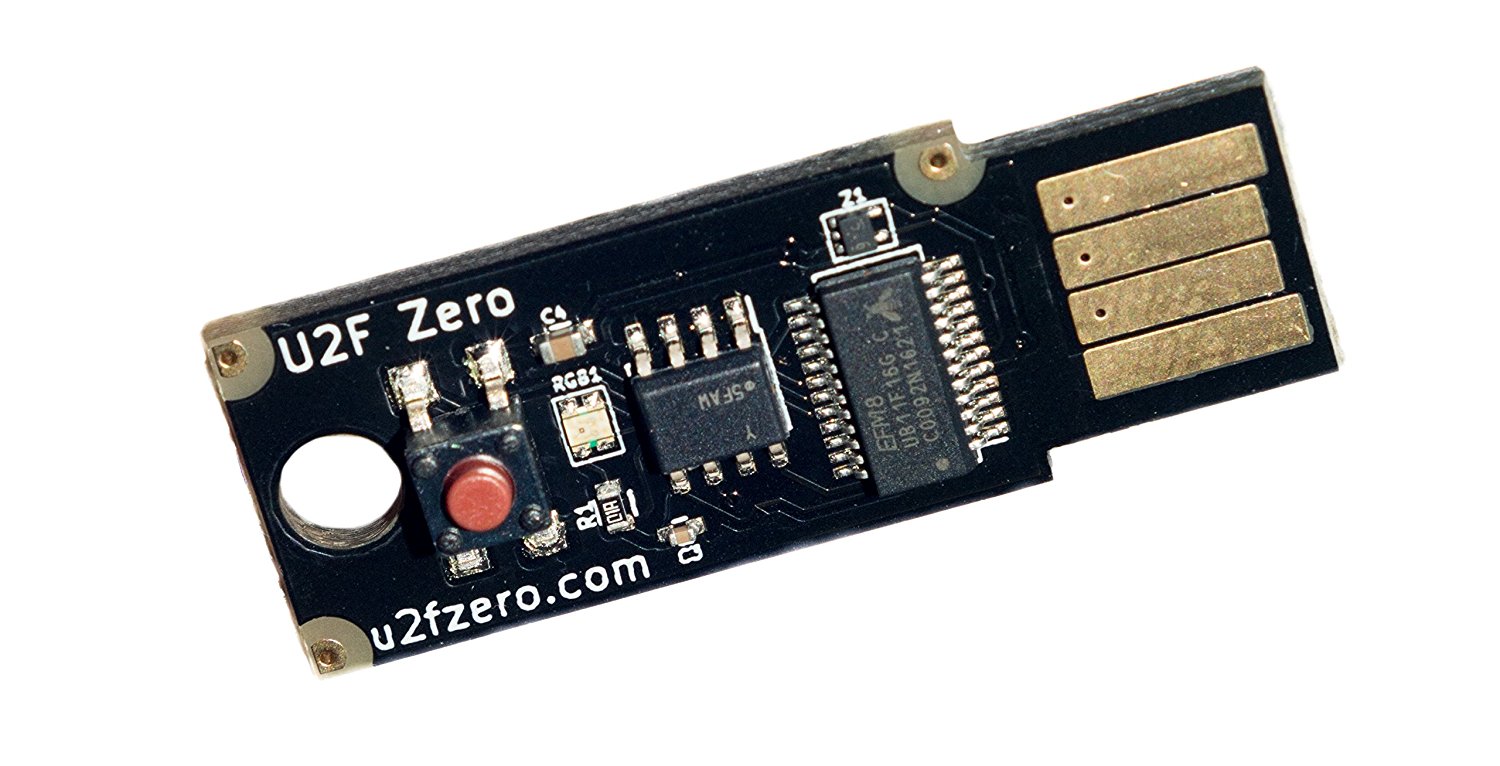
It is a bare bones little gadget: a naked PCB that implements the Universal 2nd Factor authentication standard. This particular one is open source and very inexpensive. You can get slightly more robust and commercially supported products from Yubico (and probably others, since it is an open standard).

The idea is that you enable U2F on a website like Facebook, which will then ask you to insert your key into a USB port and click the button. This registers this device. When you next try to login, it will ask you to reinsert your key and press the button. You don’t have to copy any numbers, just one button push and you are good to go.

I’ve only had my key for a few days, and the only application that I’ve really played with is WordPress (in fact, for the very blog that you are looking at). Here are some of my early observations:

  1. U2F needs to be supported by your browser. I use Chrome on virtually every machine I have, which is well supported on all the platforms I commonly use. I’ve tested it on Linux and Mac OS.
  2. To add two factor authentication to WordPress, you need to use a plugin. I used the Two Factor plugin, by George Stephanis. This adds some additional entry to the “User Profile” section of WordPress, and allows you to enable two factor authentication in a variety of ways (via email, google Authenticator, or U2F).
  3. If you use U2F, then your website must use HTTPS. This was initially what spawned my switch to HTTPS several days ago, as documented here.
  4. You can then register your new key for the user. I initially had some difficulty with this, and traced the problem to a permissions problem in Linux. You need to make sure that the udevfs recognizes the key appropriately. You can find the directions here on github. (The key itself shipped with no documentation.)
  5. And, it works.

By no means have I done a security audit of the device. I have no real insight into how it works. It’s not clear to me how physically robust the device is, or whether it represents a significant improvement over just using Google Authenticator. I will continue to play with it for now. One of the things on my list is to implement a webserver of my own in Python that uses the U2F protocol as well. Eventually I’ll try it with other applications (github probably next) but will probably continue to use Google Authenticator for many others.

If you are interested in this topic, feel free to leave a comment or ask a question.

Addendum: The github page for the U2F Zero indicates that the CPU it uses is a “Universal Bee” which is made by Silicon Labs, which cost about $1.38 in quantity one, and are optimized for low power USB applications. It has 16K of flash memory, and 2K of RAM.

Ordered some ESP8266 boards in an Arduino form factor…

r2_1The ESP8266 is an amazing little processor: cheap and capable and (most interestingly) WiFi enabled. I have some of the older “nodemcu” boards that I got for about $7 each, but there are newer alternatives that include up to 4M of flash memory, and a variety of interesting form factors.

I noticed that WeMos was producing these boards which nominally have the Arduino Uno form factor. With a 15% discount coupon from banggood.com, I got three of them on order for under $16. I’ll let you know how they work out. I’m normally not a fan of the classic Arduino shape, but I do have a number of 3d printed cases and bumpers that can be used, which makes them relatively easy to mount and wire up.

If you want to program the ESP8266, you might try using platformio, which makes it easy to use both the native SDK as well as a simpler Arduino based framework. It also supports a number of other embedded architectures, including the Arduino, but allows you to use your own editor and the like to build and organize your code. Worth looking at.

Replacing the LCD Panel in a Samsung 303C Chromebook…

In what quite possibly might be the most boring video ever produced, I recorded myself changing the LCD panel out of my Chromebook. It’s 17 minutes of riveting youtube goodness. Skip down to the bottom if you want to watch.

But here’s the story if you’d rather just read a paragraph. My wife bought me this little Samsung 303C Chromebook a while ago, and unlike the netbook that I had years before, I actually found this gadget to be pretty useful. For those who may not know about Chromebooks, they run ChromeOS, an operating system designed by Google to mostly run web applications. You can read more about it, but essentially it’s an OS designed to run a browser and web applications. I use it mostly to do web browsing, email, writing (using Google Docs), Netflix, and running ssh to access other machines on my network. For that, it’s great: it has long battery life, is lightweight, and is cheap (list price is $200 or so). I have taken it when traveling instead of a tablet when I may need to get some writing done, and when bringing a full laptop would be more cumbersome.

Sadly, a few days ago I realized that I had somehow managed to crack the LCD screen on it. I tend to be pretty casual with the thing, so I probably kicked it around while it was on the floor or something. I was kind of bummed. But a little quick googling revealed that I could get a replacement screen from Amazon for about $39 with free shipping courtesy of Amazon Prime. I ordered it on Tuesday night, and got it Thursday.

The replacement is very, very simple: I suspect having done it once I could probably do it in less than five minutes. The procedure is basically to turn off the unit, pop off the bezel (just use your fingers), and remove four screws that hold the screen in place. Then, you have to disconnect the ribbon connector, which I found to be a little unobvious, and results in a boring middle part of this video, where I am trying to understand exactly how to release the catch. I was overly cautious, and wanted to make sure I knew what I was doing, so I stopped and rewatched another video, which didn’t help a lot. In the end, I realized what I was staring at: there is a C shaped hasp which goes around the outside of the connector on the board, and had a plastic tab which was hidden under a layer of tape above. Once I figured that out, I used a small screwdriver to lift the edge, and disconnected the ribbon cable. After that, it was entirely easy: just reverse the process, attach the cable, secure the four screws again, pop the bezel on, and voila! Screen works again.

At the very end of the video, you can hear me muttering a little bit about the “black line”. When I reinstalled it, it looks a little like the active area of the screen is a little offset: I see a black gap at the top, and the active lines of the screen at the very bottom are very close (or even hidden a little) by the bezel. I was wondering if perhaps I should have secured the panel with the alternate set of screw holes. Rewatching the video, it appears that I used the same set that the original did, but I might still disassemble it to adjust this and see if it makes the result better.

In any case, it was a quick and easy fix, and I’m glad my trusty little Chromebook is back and running.

Regarding production: I filmed it all with my GoPro Hero 3 (white). I apologize a bit for the audio, I’m picking up a bit of noise, and didn’t have time to fix it. I assembled the two clips using an FFMPEG script that I have used before, with one addition: I realized that I typed my login password on camera, thought that might be a bad idea, so I figured out how to blur out the image at that time. Fun! I might make a new article about that later, when I develop some more interesting examples.

Hope this helps someone in the future!

A Big Bin Full O’ Development Boards at BrainWagon Labs…

I have an odd obsession with small, relatively cheap hardware development boards. Over the last few years, I’ve acquired a bunch of them, from Arduino to Raspberry Pi to BeagleBone Black. I thought it might be nice to just do a short video showing what I have around. So I did. Here’s a little 25 minute video demoing what I’ve got lying around.

Here’s a bunch of links to some of the boards I mentioned:

  • Arduino, the classic board. Based upon the ATMEGA328, an 8 bit processor, 32K of flash, 20Mhz. Great user community.
  • Beagle Bone Black Very cool Linux based machine.
  • Raspberry Pi Perhaps my favorite board, I don’t have the version 2 board yet, but the version B+ boards are really nice. I particularly like the Pi Camera boards you can use with them.
  • WRTNode A very cool, very cheap Linux box, with WiFi. Runs OpenWRT, a stripped down version of Linux, but still cool.
  • Wild Fire board A very nifty little board by Wicked Devices, who supplied me with a couple. During the video, I mentioned that I thought these boards were a bit expensive, but checking their website, I see them selling for about $49. If you need an Arduino compatible board with some extra punch, it’s a great little board.
  • ESP8266 The tiniest and cheapest board that I had. Often used as simple serial->WiFi chips, they are actually quite powerful and can be reprogrammed. This lua based firmware is a cool example.

Another bit of programmable hardware: the WRTnode

I’ve got a weak spot for cheap, programmable hardware. In my junk drawer I’ve got a collection of Arduinos, Parallax Propellor boards, a couple of STM32 based ARM boards, and several Beagle Bone Blacks and Raspberry Pis. Today, another entry arrived: the WRTnode.

I’ve only had it out of the box for a few hours, and a little bit of tinkering, but here are my initial impressions.

WRTnodeA few basics first: it’s a small, cheap Linux computer. Nominally, the list price is supposed to be $25, but I ordered mine via the Amazon store and paid a bit of a premium: it cost $35, but shipped in two days via Amazon Prime. It comes in a small plastic box the size of an Altoids tin, and includes a little USB cable that allows you to chain an extra USB device to it, as well as provide power. I plugged mine into a little D-Link USB hub I had lying around. Seems to work fine.

In terms of capability, it falls somewhere between the Arduino and a Raspberry Pi. The processor is actually not ARM based, it’s an MTK MT7620N MIPS processor that runs at 580Mhz. It has a 512Mbit DDR2 RAM and 128Mbit of SPI flash ROM. This is quite a bit less than the Raspberry Pi, but it does have one cool added feature: it’s got a 300Mbit wireless networking chip on board which can do 802.11n. It also can handle USB host mode. Basically, you can think of this as the brains to a fairly reasonable wireless router. It’s a very small board, only 45mm x 50mm, and includes 23 GPIO pins, as well as JTAG and SPI.

Because of it’s rather limited memory, it can’t run full Debian. Instead, it runs the OpenWRT distribution, a small distribution which is often used on tiny embedded boxes that serve as routers. It runs BusyBox, has the tiny shell “ash”, as well as the LuCI web based configuration interface, which is based upon the uhttpd webserver.

Setting it up was pretty darned easy: I plugged the supplied USB cable into it, and the other end into my powered hub. A small blue LED comes on, and about 20 seconds later, a new wireless access point was visible called WRTnode9DDB. If you attach to that network, you are asked for a network password, which defaults to 12345678, and then you can telnet to the device, which defaults to IP address 192.168.8.1. You can login as root with no password. If you run passwd you can enter a new password, and then you can use ssh to connect to it.

Screen Shot 2015-01-02 at 9.14.47 PM

Nifty! If you cat /proc/cpuinfo you can get information about the processor:

system type		: Ralink MT7620N ver:2 eco:6
machine			: WRTNODE
processor		: 0
cpu model		: MIPS 24KEc V5.0
BogoMIPS		: 398.13
wait instruction	: yes
microsecond timers	: yes
tlb_entries		: 32
extra interrupt vector	: yes
hardware watchpoint	: yes, count: 4, address/irw mask: [0x0ffc, 0x0ffc, 0x0ffb, 0x0ffb]
isa			: mips1 mips2 mips32r1 mips32r2
ASEs implemented	: mips16 dsp
shadow register sets	: 1
kscratch registers	: 0
core			: 0
VCED exceptions		: not available
VCEI exceptions		: not available

and ditto for cat /proc/meminfo:

MemTotal:          61852 kB
MemFree:           22516 kB
Buffers:            4828 kB
Cached:            17928 kB
SwapCached:            0 kB
Active:            14292 kB
Inactive:          10744 kB
Active(anon):       3772 kB
Inactive(anon):       76 kB
Active(file):      10520 kB
Inactive(file):    10668 kB
Unevictable:           0 kB
Mlocked:               0 kB
SwapTotal:             0 kB
SwapFree:              0 kB
Dirty:                 0 kB
Writeback:             0 kB
AnonPages:          2296 kB
Mapped:             1960 kB
Shmem:              1568 kB
Slab:               6028 kB
SReclaimable:       1784 kB
SUnreclaim:         4244 kB
KernelStack:         296 kB
PageTables:          292 kB
NFS_Unstable:          0 kB
Bounce:                0 kB
WritebackTmp:          0 kB
CommitLimit:       30924 kB
Committed_AS:       6948 kB
VmallocTotal:    1048372 kB
VmallocUsed:        2204 kB
VmallocChunk:    1032516 kB

OpenWRT isn’t as full featured as some Linux distributions, but it’s not bad. It includes ssh, Python and Lua. It’s got vi. It runs its own small package manager called opkg, which has a pretty good selection of precompiled packages available for install (although its good to be careful, you don’t have an infinite amount of space). Scanning the list, it’s got installation packages for lighttpd, Asterix, and a bunch of other goodies.

I haven’t had a lot of time to mess with it, but I’m fairly impressed so far. I have a feeling I’m going to miss having a C compiler/make setup on the board, but it looks to be pretty simple to cross compile to it from my main Linux box. I have already rebuilt the distribution, and will probably try flashing it sometime soon.

If you are in the market for a little machine with features like this (esp. with WiFi), it might be worth it.

Tiny-Tim: A DTL computer (in progress)

Previously, I had linked to Rory Mangles’ experiments with relay based computers. He had an incredible build of a relay logic computer called Tiny-8 which used paper as program mamory, inked with a pattern which could be read by photo sensors to sequence the control logic in his computer. I thought it was amazing. But surfing back to his website, he appears to now by working Tiny Tim, a diode-transistor logic (DTL) computer, made from discrete 2N3904 transistors and Schottky diodes. Sadly, there isn’t much actual build here yet (this update is six months old) but there is some good information, and I hope that he’ll pick up the project again.

Here is a link to his video of a simple flip flop:


A Tale of Two Gadgets: the TonidoPlug 2 and a Bus Pirate…

A few days ago, I mentioned that one of my servers had died. I spent some time thinking about how I would replace it. I like having a 24/7 hooked up to the Internet to serve as a file drop and a place where I can use SSH to connect to other devices on my home network, but the machine need not be hugely fast, and it would probably be better if it were fairly low power. My previous server drew about 30 watts, and I suspected that I could get something more compact and lower power to replace it.

So, I ordered a TonidoPlug 2. It’s a cute little server based upon the Sheeva Plug computer concept, but includes space to insert a 2.5″ SATA laptop drive. It has all sorts of “personal cloud” applications running on it, which I had no interest in, but doing a bit more research, I found that I could install ArchLinux on the internal hard drive, and it would boot to that automatically. Cool, think I. I ordered mine off Amazon.

It arrived yesterday. I powered it up, verified that it worked in its default configuration, then proceeded to follow the directions on the ArchLinux ARM page. Upon reboot… not good. I ended up with a flashing red LED, and the network never comes back up. So, I pulled the internal drive, and it reboots back to its default configuration.

I then start tracking through various support and Wiki links. I find that some people have had difficulty booting from the internal drives, and the Tonido support guys have been very coy, claiming that “we don’t support that”. Frown. Not good.

But in doing this research, I found that it was possible to access the boot loader and serial console. On the bottom side of the tonido is a nice little rubber cover, concealing 4 pins. Most people seem to make a small adapter to use an FTDI-serial adapter cable with it (the six pin ones like you would use for the Arduino), but I had a Bus Pirate sitting around, and I thought that it might work. And… it did!

In case anyone else (or me in the future) wants to know how to do this:

  • The four pins are Vcc, Rx, Tx, and GND, starting from the power supply side and working toward the USB/Ethernet cable side.
  • I just hooked up MOSI to RX, MISO to TX, and GND to GND
  • To use the Bus Pirate with my Mac laptop, I like to use GNU screen. If you run “screen /dev/tty.usbserial-AH00MPIK 115200” (your tty device will likely be different), it makes a convenient terminal emulator. From there, you can access the Bus Pirate, configure it in UART mode with a baud rate of 115200 and sensible other defaults.
  • You can then use the Bus Pirate as a UART bridge by invoking the “(1)” macro. You’ll then essentially be talking directly to the Tonido via the BusPirate.
  • Using screen’s C-a H command, you can start a log file, which will record all the output from the serial port. Doing the command again will stop logging.

Hooking it up, I got lots of cool info from the Tonido:

         __  __                      _ _
        |  \/  | __ _ _ ____   _____| | |
        | |\/| |/ _` | '__\ \ / / _ \ | |
        | |  | | (_| | |   \ V /  __/ | |
        |_|  |_|\__,_|_|    \_/ \___|_|_|
 _   _     ____              _
| | | |   | __ )  ___   ___ | |_ 
| | | |___|  _ \ / _ \ / _ \| __| 
| |_| |___| |_) | (_) | (_) | |_ 
 \___/    |____/ \___/ \___/ \__| 
 ** MARVELL BOARD: DB-88F6282A-BP LE 

U-Boot 1.1.4 (Sep 13 2011 - 13:25:05) Marvell version: 3.4.27
USISH-SMB Ver: topkick1281p2-001-008-20110913-codelathe

U-Boot code: 00600000 -> 0067FFF0  BSS: -> 006D0120

Soc: MV88F1155 Rev 1 (DDR2)
CPU running @ 800Mhz L2 running @ 400Mhz
SysClock = 400Mhz , TClock = 200Mhz 

DRAM unknown CAL  tRP = 8 tRAS = 20 tRCD=8
DRAM CS[0] base 0x00000000   size 512MB 
DRAM Total size 512MB  16bit width
Addresses 8M - 0M are saved for the U-Boot usage.
Mem malloc Initialization (8M - 7M): Done
NAND:512 MB
Flash:  0 kB

CPU : Marvell Feroceon (Rev 1)

Streaming disabled 
Write allocate disabled


USB 0: host mode
PEX 0: interface detected no Link.
Net:   egiga0 [PRIME]
Hit any key to stop autoboot:  0 
(Re)start USB...
USB:   scanning bus for devices... 1 USB Device(s) found
Waiting for storage device(s) to settle before scanning...
0 Storage Device(s) found
** Bad partition 1 **
## Booting image at 00800000 ...
Bad Magic Number
Saving Environment to NAND...
Erasing Nand...Writing to Nand... done

Reset IDE: 
Marvell Serial ATA Adapter
Integrated Sata device found
[0 0 0]: Enable DMA mode (5)
  Device 0 @ 0 0:
Model: TOSHIBA MK6465GSX                        Firm: GJ003M   Ser#:            50OAC319T
            Type: Hard Disk
            Supports 48-bit addressing
            Capacity: 610480.3 MB = 596.1 GB (1250263728 x 512)


** Unable to read "/boot/uImage" from ide 0:1 **
## Booting image at 00800000 ...
Bad Magic Number
Saving Environment to NAND...
Erasing Nand...Writing to Nand... done

NAND read: device 0 offset 0x200000, size 0x600000

6291456 bytes read: OK

## Booting image at 01200000 ...
   Image Name:   Linux-2.6.31.8-topkick1281p2-001
   Created:      2011-11-10   3:58:11 UTC
   Image Type:   ARM Linux Kernel Image (uncompressed)
   Data Size:    3121408 Bytes =  3 MB
   Load Address: 00008000
   Entry Point:  00008000
   Verifying Checksum ... OK
OK

Starting kernel ...

Uncompressing Linux................................................................................................................................................................................................... done, booting the kernel.
Linux version 2.6.31.8-topkick1281p2-001-004-20101214 (andrew@localhost.localdomain) (gcc version 3.4.4 (release) (CodeSourcery ARM 2005q3-2)) #2 Thu Nov 10 11:58:07 CST 2011
CPU: Feroceon 88FR131 [56251311] revision 1 (ARMv5TE), cr=00053977
CPU: VIVT data cache, VIVT instruction cache
Machine: Feroceon-KW
Using UBoot passing parameters structure
Memory policy: ECC disabled, Data cache writeback
Built 1 zonelists in Zone order, mobility grouping on.  Total pages: 130048
Kernel command line: console=ttyS0,115200;version=topkick1281p2-001-006-20101103 mtdparts=nand_mtd:0x180000@0(u-boot),0x20000@0x180000(u-boot-env),0x600000@0x200000(uImage),0x1f800000@0x800000(rootfs) ubi.mtd=3 root=ubi0:rootfs rootfstype=ubifs rootdelay=10
PID hash table entries: 2048 (order: 11, 8192 bytes)
Dentry cache hash table entries: 65536 (order: 6, 262144 bytes)
Inode-cache hash table entries: 32768 (order: 5, 131072 bytes)
Memory: 512MB = 512MB total
Memory: 513280KB available (5612K code, 319K data, 148K init, 0K highmem)
NR_IRQS:128
Console: colour dummy device 80x30
Calibrating delay loop... 794.62 BogoMIPS (lpj=3973120)
Mount-cache hash table entries: 512
CPU: Testing write buffer coherency: ok
xor: measuring software checksum speed
   arm4regs  :   723.200 MB/sec
   8regs     :   433.600 MB/sec
   32regs    :   600.800 MB/sec
xor: using function: arm4regs (723.200 MB/sec)
NET: Registered protocol family 16
Feroceon L2: Enabling L2
Feroceon L2: Cache support initialised.

CPU Interface
-------------
SDRAM_CS0 ....base 00000000, size 512MB 
SDRAM_CS1 ....disable
SDRAM_CS2 ....disable
SDRAM_CS3 ....disable
PEX0_MEM ....base e8000000, size 128MB 
PEX0_IO ....base f2000000, size   1MB 
INTER_REGS ....base f1000000, size   1MB 
NFLASH_CS ....base fa000000, size   2MB 
SPI_CS ....base f4000000, size  16MB 
BOOT_ROM_CS ....no such
DEV_BOOTCS ....no such
CRYPT_ENG ....base f0000000, size   2MB 

  Marvell Development Board (LSP Version KW_LSP_5.0.3)-- DB-88F6282A-BP  Soc: MV88F1155 Rev 1 LE

 Detected Tclk 200000000 and SysClk 400000000 
MV Buttons Device Load
Marvell USB EHCI Host controller #0: df837740
PEX0 interface detected no Link.
PCI: bus0: Fast back to back transfers enabled
bio: create slab <bio-0> at 0
SCSI subsystem initialized
usbcore: registered new interface driver usbfs
usbcore: registered new interface driver hub
usbcore: registered new device driver usb
raid6: int32x1     72 MB/s
raid6: int32x2    101 MB/s
raid6: int32x4     88 MB/s
raid6: int32x8     80 MB/s
raid6: using algorithm int32x2 (101 MB/s)
cfg80211: Calling CRDA to update world regulatory domain
NET: Registered protocol family 2
IP route cache hash table entries: 16384 (order: 4, 65536 bytes)
TCP established hash table entries: 65536 (order: 7, 524288 bytes)
TCP bind hash table entries: 65536 (order: 6, 262144 bytes)
TCP: Hash tables configured (established 65536 bind 65536)
TCP reno registered
NET: Registered protocol family 1
rtc mv_rtc: rtc core: registered kw-rtc as rtc0
RTC registered
cpufreq: Init kirkwood cpufreq driver
XOR registered 4 channels
XOR 2nd invalidate WA enabled
mvCesaInit: sessions=640, queue=64, pSram=f0000000
Warning: TS unit is powered off.
MV Buttons Driver Load
JFFS2 version 2.2. (NAND) © 2001-2006 Red Hat, Inc.
SGI XFS with security attributes, large block/inode numbers, no debug enabled
msgmni has been set to 1002
alg: No test for cipher_null (cipher_null-generic)
alg: No test for ecb(cipher_null) (ecb-cipher_null)
alg: No test for digest_null (digest_null-generic)
alg: No test for compress_null (compress_null-generic)
alg: No test for stdrng (krng)
alg: No test for hmac(digest_null) (hmac(digest_null-generic))
async_tx: api initialized (sync-only)
io scheduler noop registered
io scheduler anticipatory registered (default)
Serial: 8250/16550 driver, 4 ports, IRQ sharing disabled
serial8250.0: ttyS0 at MMIO 0xf1012000 (irq = 33) is a 16550A
console [ttyS0] enabled
Integrated Sata device found
IRQ 21/mvSata: IRQF_DISABLED is not guaranteed on shared IRQs
scsi0 : Marvell SCSI to SATA adapter
scsi1 : Marvell SCSI to SATA adapter
scsi 0:0:0:0: Direct-Access     TOSHIBA  MK6465GSX        GJ00 PQ: 0 ANSI: 5
sd 0:0:0:0: [sda] Sector size 0 reported, assuming 512.
sd 0:0:0:0: [sda] 1250263728 512-byte logical blocks: (640 GB/596 GiB)
sd 0:0:0:0: [sda] 0-byte physical blocks
sd 0:0:0:0: [sda] Write Protect is off
sd 0:0:0:0: Attached scsi generic sg0 type 0
Loading Marvell Ethernet Driver:
  o Cached descriptors in DRAM
  o DRAM SW cache-coherency
  o 2 Giga ports supported
  o Multi RX Queue support - 4 RX queues
  o Multi TX Queue support - 2 TX Queues
  o TCP segmentation offload (TSO) supported
  o Large Receive offload (LRO) supported
  o Receive checksum offload supported
  o Transmit checksum offload supported
  o Network Fast Processing (Routing) supported - (Disabled)
  o Network Fast Processing (NAT) supported
  o Driver ERROR statistics enabled
  o Driver INFO statistics enabled
  o Proc tool API enabled
  o SKB Reuse supported - (Disabled)
  o SKB Recycle supported - (Disabled)
  o Gateway support enabled
     o Using Marvell Header Mode
     o L2 IGMP support
  o Rx descripors: q0=128 q1=128 q2=128 q3=128
  o Tx descripors: q0=532 q1=532
  o Loading network interface(s):
    o  register under mv88fx_eth platform
sd 0:0:0:0: [sda] Write cache: enabled, read cache: enabled, supports DPO and FUA
sd 0:0:0:0: [sda] Sector size 0 reported, assuming 512.
    o eth0, ifindex = 2, GbE port = 0

Warning: Giga 1 is Powered Off

Warning: Giga 1 is Powered Off

mvFpRuleDb (df280000): 16384 entries, 65536 bytes
Intel(R) PRO/1000 Network Driver - version 7.3.21-k3-NAPI
Copyright (c) 1999-2006 Intel Corporation.
e1000e: Intel(R) PRO/1000 Network Driver - 1.0.2-k2
e1000e: Copyright (c) 1999-2008 Intel Corporation.
e100: Intel(R) PRO/100 Network Driver, 3.5.24-k2-NAPI
e100: Copyright(c) 1999-2006 Intel Corporation
 sda:
PPP generic driver version 2.4.2
PPP Deflate Compression module registered
PPP BSD Compression module registered
PPP MPPE Compression module registered
NET: Registered protocol family 24
PPPoL2TP kernel driver, V1.0
Using Hamming 1-bit ECC for NAND device
NAND device: Manufacturer ID: 0xad, Chip ID: 0xdc (Hynix NAND 512MiB 3,3V 8-bit)
Scanning device for bad blocks
Bad eraseblock 1064 at 0x000008500000
Bad eraseblock 1065 at 0x000008520000
Bad eraseblock 1884 at 0x00000eb80000
Bad eraseblock 1885 at 0x00000eba0000
Bad eraseblock 2038 at 0x00000fec0000
Bad eraseblock 2039 at 0x00000fee0000
Bad eraseblock 2580 at 0x000014280000
Bad eraseblock 2581 at 0x0000142a0000
Bad eraseblock 2606 at 0x0000145c0000
Bad eraseblock 2844 at 0x000016380000
Bad eraseblock 3269 at 0x0000198a0000
Bad eraseblock 3547 at 0x00001bb60000
4 cmdlinepart partitions found on MTD device nand_mtd
Using command line partition definition
Creating 4 MTD partitions on "nand_mtd":
0x000000000000-0x000000180000 : "u-boot"
 sda1
sd 0:0:0:0: [sda] Sector size 0 reported, assuming 512.
0x000000180000-0x0000001a0000 : "u-boot-env"
sd 0:0:0:0: [sda] Attached SCSI disk
0x000000200000-0x000000800000 : "uImage"
0x000000800000-0x000020000000 : "rootfs"
UBI: attaching mtd3 to ubi0
UBI: physical eraseblock size:   131072 bytes (128 KiB)
UBI: logical eraseblock size:    129024 bytes
UBI: smallest flash I/O unit:    2048
UBI: sub-page size:              512
UBI: VID header offset:          512 (aligned 512)
UBI: data offset:                2048
UBI: attached mtd3 to ubi0
UBI: MTD device name:            "rootfs"
UBI: MTD device size:            504 MiB
UBI: number of good PEBs:        4020
UBI: number of bad PEBs:         12
UBI: max. allowed volumes:       128
UBI: wear-leveling threshold:    4096
UBI: number of internal volumes: 1
UBI: number of user volumes:     1
UBI: available PEBs:             75
UBI: total number of reserved PEBs: 3945
UBI: number of PEBs reserved for bad PEB handling: 40
UBI: max/mean erase counter: 3/1
UBI: image sequence number: 0
ehci_hcd: USB 2.0 'Enhanced' Host Controller (EHCI) Driver
ehci_marvell ehci_marvell.70059: Marvell Orion EHCI
ehci_marvell ehci_marvell.70059: new USB bus registered, assigned bus number 1
UBI: background thread "ubi_bgt0d" started, PID 480
ehci_marvell ehci_marvell.70059: irq 19, io base 0xf1050100
ehci_marvell ehci_marvell.70059: USB 2.0 started, EHCI 1.00
usb usb1: configuration #1 chosen from 1 choice
hub 1-0:1.0: USB hub found
hub 1-0:1.0: 1 port detected
ohci_hcd: USB 1.1 'Open' Host Controller (OHCI) Driver
uhci_hcd: USB Universal Host Controller Interface driver
usbcore: registered new interface driver usblp
Initializing USB Mass Storage driver...
usbcore: registered new interface driver usb-storage
USB Mass Storage support registered.
usbcore: registered new interface driver ums-datafab
usbcore: registered new interface driver ums-freecom
usbcore: registered new interface driver ums-jumpshot
usbcore: registered new interface driver ums-sddr09
usbcore: registered new interface driver ums-sddr55
usbcore: registered new interface driver ums-usbat
pwrctl: dev_t_NO. = 0xdd00000, major = 221
pwrctl: request the irq power off registered. 
mice: PS/2 mouse device common for all mice
i2c /dev entries driver
Linux telephony interface: v1.00
md: linear personality registered for level -1
md: raid0 personality registered for level 0
md: raid1 personality registered for level 1
md: raid6 personality registered for level 6
md: raid5 personality registered for level 5
md: raid4 personality registered for level 4
device-mapper: ioctl: 4.15.0-ioctl (2009-04-01) initialised: dm-devel@redhat.com
sdhci: Secure Digital Host Controller Interface driver
sdhci: Copyright(c) Pierre Ossman
mmc0: mvsdio driver initialized, lacking card detect (fall back to polling)
Advanced Linux Sound Architecture Driver Version 1.0.20.
No device for DAI CS42L51
ALSA device list:
  No soundcards found.
nf_conntrack version 0.5.0 (8192 buckets, 32768 max)
mvFpNatDb (df360000): 16384 entries, 65536 bytes
ip_tables: (C) 2000-2006 Netfilter Core Team
TCP cubic registered
NET: Registered protocol family 17
NFP (fdb) init 256 entries, 1024 bytes
RPC: Registered udp transport module.
RPC: Registered tcp transport module.
802.1Q VLAN Support v1.8 Ben Greear <greearb@candelatech.com>
All bugs added by David S. Miller <davem@redhat.com>
rtc mv_rtc: setting system clock to 2012-03-31 01:20:22 UTC (1333156822)
Waiting 10sec before mounting root device...
mmc0: new high speed SDIO card at address 0001
md: Waiting for all devices to be available before autodetect
md: If you don't use raid, use raid=noautodetect
md: Autodetecting RAID arrays.
md: Scanned 0 and added 0 devices.
md: autorun ...
md: ... autorun DONE.
UBIFS: mounted UBI device 0, volume 0, name "rootfs"
UBIFS: file system size:   501387264 bytes (489636 KiB, 478 MiB, 3886 LEBs)
UBIFS: journal size:       25159680 bytes (24570 KiB, 23 MiB, 195 LEBs)
UBIFS: media format:       w4/r0 (latest is w4/r0)
UBIFS: default compressor: lzo
UBIFS: reserved for root:  4952683 bytes (4836 KiB)
VFS: Mounted root (ubifs filesystem) on device 0:11.
Freeing init memory: 148K
Using makefile-style concurrent boot in runlevel S.
Starting the hotplug events dispatcher: udevd.
Synthesizing the initial hotplug events...done.
Waiting for /dev to be fully populated...done.
Setting parameters of disc: (none).
Activating swap...done.
Starting early crypto disks...done.
Starting remaining crypto disks...done.
Loading kernel modules...done.
Cleaning up ifupdown....
Setting up networking....
Activating lvm and md swap...done.
Checking file systems...fsck from util-linux-ng 2.17.2
done.
Mounting local filesystems...done.
Activating swapfile swap...done.
Cleaning up temporary files....
Setting kernel variables ...done.
Configuring network interfaces...Internet Systems Consortium DHCP Client 4.1.1-P1
Copyright 2004-2010 Internet Systems Consortium.
All rights reserved.
For info, please visit https://www.isc.org/software/dhcp/

eth0: started
Listening on LPF/eth0/40:2c:f4:bc:8b:c9
Sending on   LPF/eth0/40:2c:f4:bc:8b:c9
Sending on   Socket/fallback
DHCPDISCOVER on eth0 to 255.255.255.255 port 67 interval 4
DHCPDISCOVER on eth0 to 255.255.255.255 port 67 interval 5
DHCPDISCOVER on eth0 to 255.255.255.255 port 67 interval 13
DHCPDISCOVER on eth0 to 255.255.255.255 port 67 interval 10
DHCPDISCOVER on eth0 to 255.255.255.255 port 67 interval 14
DHCPDISCOVER on eth0 to 255.255.255.255 port 67 interval 8
DHCPDISCOVER on eth0 to 255.255.255.255 port 67 interval 7
No DHCPOFFERS received.
No working leases in persistent database - sleeping.
done.
Cleaning up temporary files....
fuse init (API version 7.12)
Using makefile-style concurrent boot in runlevel 2.
Network Interface Plugging Daemon...start eth0...done.
Starting enhanced syslogd: rsyslogd.
Starting Samba daemons: nmbd smbdStarting periodic command scheduler: cron.
.
Starting system message bus: dbus.
Starting OpenBSD Secure Shell server: sshd.
EXT2-fs warning: mounting unchecked fs, running e2fsck is recommended

Debian GNU/Linux 6.0 TonidoPlug2 ttyS0

TonidoPlug2 login: --2012-03-30 18:21:50--  http://patch.codelathe.com/firmware/tonidoplug2/updates.list
Resolving patch.codelathe.com... failed: Name or service not known.
wget: unable to resolve host address “patch.codelathe.com”

Debian GNU/Linux 6.0 TonidoPlug2 ttyS0

TonidoPlug2 login: root
Password: 
Last login: Fri Mar 30 18:16:16 PDT 2012 on ttyS0
Linux TonidoPlug2 2.6.31.8-topkick1281p2-001-004-20101214 #2 Thu Nov 10 11:58:07 CST 2011 armv5tel

The programs included with the Debian GNU/Linux system are free software;
the exact distribution terms for each program are described in the
individual files in /usr/share/doc/*/copyright.

Debian GNU/Linux comes with ABSOLUTELY NO WARRANTY, to the extent
permitted by applicable law.
root@TonidoPlug2:~# 

I suspect I’ll be able to debug it a lot better tomorrow.

The Little Engine that Could…

In my home office, I have a machine called “fishtank”. I realized that I first bought it back in 2002, and since then it has been running various flavors of FreeBSD (probably beginning around 4.6 or so, currently running 7.2). At various times I’ve added or upgraded disk drives to it. While a power failure just two weeks ago reset it’s uptime, it’s had uptimes in excess of six hundred days on at least two occasions. I use it as an ssh server, file repository, and generally just a net accessible resource for generic computing tasks.

But the other day, I wanted to generate some new maps for my website using some code that I had never tried before, the Matplotlib Basemap Toolkit. There were already port files in FreeBSD, so I thought I’d try it out. So, I set it running with portmaster, and walked away.

The build failed.

Digging in, I found that it failed while building gcc (why it needed to build a new version of gcc I’m not sure, but it thinks it did). And it turns out it just flat ran out of memory.

I asked the quite natural question, “how much memory does this thing have?”

The answer: 256 megabytes. With less than 500 megabytes of swap.

I think it’s time to consider an upgrade. I could put 1G of memory in it, but that seems pretty lame. I think I’ll replace it with a small mini-desktop. I’m looking for an inexpensive, relatively low power and most importantly quiet server box. Anyone have any recommendations?

Sprites mods – CP/M on an AVR

I’ve always been fascinated by emulation and virtual machines, as well as retro-computing: resurrecting the old machines of my past. I never owned an old CP/M machine, but there are still some neat projects where people construct there own, and simulators like SIMH and YAZE-AG are good software simulators. But what I always wondered was whether a small microcontroller like an Atmel AVR could simulate an 8080 or Z80 fast enough to simulate these older machines.

And of course, today I found a link to someone who did just that. With a remarkably simple chunk of hardware. One AVR, a dynamic RAM, and an SD card to serve as a mass storage device. The combination is good enough to run Zork. I’m suitably impressed. The design and code are all GPL.

Sprites mods – CP/M on an AVR – Intro.

Magnetic core memory reborn… on an Arduino????

I may have mentioned before, I’m kind of old. One measure of how old I am is the fact that I’ve actually programmed machines that used core memory. Real core memory. Little ferrite donuts on arrays of wires.

Some time ago, I remember running across this awesome blog post from “Wayne’s Tinkering Page” which showed some experimentation in creating a driver for some surplus 1mm ferrite memory cores, effectively creating a single bit memory. I thought that was pretty darned cool. But what’s even more amazing is what Ben North and Oliver Nash have done: create a 32 bit core memory shield for an Arduino.

Links to the report and board plans, bill of materials and software

And they have an excellent report on the project, which includes a reference to a different core memory technique which employed non-destructive reads.

Magnetic core memory reborn

Very cool.

A small standalone homebrew computer: FIGnition by Libby8dev

I’m old. I learned to program as a teenager in the 1980s. Back then, we learned to program on small microcomputers. These machines weren’t very powerful, but they had a neat feature: they were self-hosted. In recent years, a large variety of small microcontrollers have become popular. Many of these have capabilities far in excess of what we had back then, but almost without fail the programming environments they use are hosted on much more powerful machines, often using code which measures tens or hundreds of megabytes.

That has always seemed a bit excessive to me, particularly since making the environments simple and self-hosted pays benefits for educational and hobbyist applications.

The FIGnition board is a project which seems to combat this trend:

FIGnition is an educational DIY computer, based around an Atmel AVR microcontroller. It uses 3 chips and only 46 components to provide a complete self-hosted computer with 8Kb of RAM; 384Kb of storage space; an 8-key keypad and PAL video output. It is interfaced and powered by USB and uses V-USB to provide firmware upgrades by implementing a usbasp device. It runs a variant of FIG-Forth.

Currently it isn’t available in the US since it doesn’t do NTSC video, but I suspect that will change soon. I’ll be looking back at this project periodically.

FIGnition – Libby8dev.

The J1 Forth CPU, running on an FPGA

Tom showed me a link to The J1 Forth CPU, a very small processor which is coded in Verilog (only 200 lines!) and can run very fast on existing FPGA boards.

It is quite an intriguing design.

Forth is an intriguing if somewhat archaic programming language. In the bygone ages of my youth, I experimented a bit with FigForth on my Atari 400, which I found to be a pretty interesting and fun programming environment, but I found most Forth code to be rather inscrutable and hard to understand, at least, it was hard if you let more than a few days pass between when you wrote it and when you read it. Nevertheless, I don’t particularly fear Forth, and have used another somewhat similar language, namely Postscript, off and on over the years.

Forth is a stack-oriented language. In languages such as C, we are used to having a call-stack which contains not just return addresses, but also local variables. Forth is a different in that local variables aren’t typically stored on the stack. Instead, Forth splits things that C would place on a single stack into two separate stacks: the data stack (often just called “the stack”) and the return stack (or “rstack”). Forth “words” (procedures) generally specify actions that manipulate one or both stacks. For instance, the “plus” word, might take the two values at the top of the data stack and replace them with their sum. The “exit” or “;” word pulls a return address off the rstack, and transfers it to the IP (instruction pointer, basically the PC).

The J1 architecture is reasonably novel in that is optimized for the execution of Forth. It is a 16 bit machine, which has an internal state consisting of a 33 (not sure why not 32, but that’s what the docs say) deep data stack, a 32 deep return stack, and a 13 bit program counter. No condition flags, modes, or registers. It has 8K words (16 bit words) of RAM, and an additional 8K words for memory mapped I/O. Instructions fall into one of 5 classes:

  • If the MSB of the instruction is a one, the remaining 15 bits specify a literal value which is pushed onto the data stack.< ./li>
  • If the upper three bits are all zero, then the remaining 13 bits specify a new value for the PC (an unconditional jump).
  • If the upper three bits are “001”, then the machine pops the data stack, and if the value is zero, the remaining 13 bits specify the new PC (conditional jump).
  • If the upper three bits are “010”, then the remaining 13 bits specify a call address. The current PC is pushed to the return stack, and the remaining 13 bits specify the new PC.
  • The remaining case (upper three bits “011”) specify an ALU instruction. This single instruction can implement many Forth words directly. The remaining 13 bits are split into 7 fields which together specify a complex action. Four bits pick one of 16 operations that are performed on the top value (and for binary operations, the next value) of the stack. A single bits says whether the top value should be copied to the next value on the data stack. Another bit specifies whether the return address should be copied to the PC. Another bit specifies whether the top of the data stack should get copied to the rstack. Two two-bit fields give a set of signed increments/decrements for the data and rstack. And a last bit specifies if a RAM store operation should happen (the next value gets stored in the address pointed at by the top value).

And that’s pretty much it! Many basewords are very, very simple and can be implemented in just one or two op codes. The resulting machine runs very fast. It’s really quite clever: all the more so because it’s actually possible to understand how it works.

It actually is fairly close to the Hack Platform defined in Noam Nisan and Shimon Schocken’s book “The Elements of Computing Systems”. The “Hack” machine has only two kinds of instructions: an “address” instruction (similar to the literal instruction above) and the “compute” instruction, similar to the last: it specifies what function the ALU computes, the destination for the ALU, and a jump condition. They use this chip to implement a more conventional stack-based virtual machine. The two machines have similar specifications and power.

I found them both to be interesting. I’ll be reading the J1 Verilog code closely.

LatticeXP2 Brevia Development Kit, with a deal breaker

I’ve been playing with a BASYS2 FPGA development kit from digilentinc.com, and pondering the world of digital system design. I chose the BASYS2 because of its low price ($70) and because it included a reasonable number of LEDs, switches, a VGA interface and a connector for a PS/2 keyboard. Still, I’ve been looking for other small, reasonably priced FPGA kits, perhaps even ones which aren’t based on the Xilinx chips. Today I learned of a nice looking little $49 kit from Lattice:

LatticeXP2 Brevia Development Kit.

While it doesn’t include the VGA or PS/2 interfaces, it does include a 1Mbit static ram on board, which perhaps makes it more interesting for experimenting with FPGA cpus. But here’s the thing: it includes a parallel port programming cable, and literally no computers I currently use have a parallel port anymore. They tel you that you need a special USB cable: the HW-USBN-2A which is not included. Oh well, think I, that can’t be too bad…

That cable costs $149.

Yes, the programming cable for this FPGA board is 3x the cost of the entire board.

Deal, broken.

Design of a simple ALU…

A couple of weeks ago, I noticed a bunch of links to a 16 bit ALU designed to operate using blocks which are defined in the game Minecraft. It got me thinking, and ordered the book that inspired that work. It contains the specification for an ALU which is very simple, and yet surprisingly powerful ALU (at least, considering the number of gates that it would take to implement it).

Here’s a C function that implements the ALU. I went ahead and just used the integer type, rather than the 16 bits specified in the Hack computer, but it doesn’t really matter what the word size is.

[sourcecode lang=”C”]
#define ZERO_X (1<<0)
#define COMP_X (1<<1)
#define ZERO_Y (1<<2)
#define COMP_Y (1<<3)
#define OP_ADD (1<<4)
#define COMP_O (1<<5)

unsigned int
alu(unsigned int x, unsigned int y, int flags)
{
unsigned int o ;

if (flags & ZERO_X) x = 0 ;
if (flags & ZERO_Y) y = 0 ;
if (flags & COMP_X) x = ~x ;
if (flags & COMP_Y) y = ~y ;
if (flags & OP_ADD)
o = x + y ;
else
o = x & y ;
if (flags & COMP_O) o = ~o ;
return o ;
}
[/sourcecode]

The function takes in two operands (x and y) and a series of six bit flags. The ZERO_X and ZERO_Y say that the X input and Z input should be set to zero. The COMP_X, COMP_Y, and COMP_O flags say that the X, Y, and output values should be bitwise negated (all the zeros become ones, and the ones zeros). The OP_ADD flag chooses one of two functions: when set, it means that the two operands should be added, otherwise, the two operands are combined with bitwise AND.

There are a surprisingly large number of interesting functions that can be calculated from this simple ALU. Well, perhaps not surprising to the hardware engineers out there, but I’ve never really thought about it. It’s obvious that you can compute functions like AND and ADD. Let’s write some defines:

[sourcecode lang=”C”]
#define AND(x,y) alu(x, y, 0)
#define ADD(x,y) alu(x, y, OP_ADD)
[/sourcecode]

You can also compute functions like OR using DeMorgan’s Law: OR(x,y) = ~(~X AND ~Y).

[sourcecode lang=”C”]
#define OR(x,y) alu(x, y, COMP_X|COMP_Y|COMP_O)
[/sourcecode]

You can make some constants such as zero and one. Zero is particularly easy, but one requires an interesting trick using twos-complement arithmetic.

[sourcecode lang=”C”]
#define ZERO(x,y) alu(x, y, ZERO_X|ZERO_Y|OP_ADD)
#define ONE(x,y) alu(x, y, ZERO_X|COMP_X|ZERO_Y|COMP_Y|OP_ADD|COMP_O)
[/sourcecode]

To make sense of the definition of ONE, you need to know that in twos-complement arithmetic, -x = ~x + 1, or in other words, -x – 1 = ~x. Look at the definition of ONE, it computes ~(~0 + ~0). After the addition, the register contains all 1s, except for the low order bit. Negating that builds a one. You can also build a -1, or even a -2.

You can also obviously get either operand, or their logical complements. There are even multiple implementations:

[sourcecode lang=”C”]
#define NOTX(x,y) alu(x, y, COMP_X|ZERO_Y|COMP_Y)
#define NOTX(x,y) alu(x, y, COMP_X|ZERO_Y|OP_ADD)
#define NOTX(x,y) alu(x, y, ZERO_Y|COMP_Y|COMP_O)
#define NOTX(x,y) alu(x, y, ZERO_Y|OP_ADD|COMP_O)
[/sourcecode]

We saw how we could add, we could also construct a subtractor:

[sourcecode lang=”C”]
#define SUB(x,y) alu(x, y, COMP_X|OP_ADD|COMP_O)
[/sourcecode]

We saw how we could compute +1 and -1, but we can also add these constants to X or Y..

[sourcecode lang=”C”]
#define DECY(x,y) alu(x, y, ZERO_X|COMP_X|OP_ADD)
#define DECX(x,y) alu(x, y, ZERO_Y|COMP_Y|OP_ADD)
#define INCY(x,y) alu(x, y, ZERO_X|COMP_X|COMP_Y|OP_ADD|COMP_O)
#define INCX(x,y) alu(x, y, COMP_X|ZERO_Y|COMP_Y|OP_ADD|COMP_O)
[/sourcecode]

I thought it was pretty neat or such a small implementation. The hardest part to implement is the adder, all the rest is a pretty trivial number of gates. If you use a simple ripple adder, even the adder is pretty small.

Addendum: Here’s a more (but not entirely) exhaustive list of functions that are implemented.

[sourcecode lang=”C”]
#define ADD(x,y) alu(x, y, OP_ADD)
#define AND(x,y) alu(x, y, 0)
#define DECX(x,y) alu(x, y, ZERO_Y|COMP_Y|OP_ADD)
#define DECY(x,y) alu(x, y, ZERO_X|COMP_X|OP_ADD)
#define INCX(x,y) alu(x, y, COMP_X|ZERO_Y|COMP_Y|OP_ADD|COMP_O)
#define INCY(x,y) alu(x, y, ZERO_X|COMP_X|COMP_Y|OP_ADD|COMP_O)
#define MINUS1(x,y) alu(x, y, COMP_X|ZERO_Y|COMP_O)
#define MINUS1(x,y) alu(x, y, ZERO_X|COMP_O)
#define MINUS1(x,y) alu(x, y, ZERO_X|COMP_X|ZERO_Y|COMP_O)
#define MINUS1(x,y) alu(x, y, ZERO_X|COMP_X|ZERO_Y|COMP_Y)
#define MINUS1(x,y) alu(x, y, ZERO_X|COMP_X|ZERO_Y|OP_ADD)
#define MINUS1(x,y) alu(x, y, ZERO_X|COMP_Y|COMP_O)
#define MINUS1(x,y) alu(x, y, ZERO_X|ZERO_Y|COMP_O)
#define MINUS1(x,y) alu(x, y, ZERO_X|ZERO_Y|COMP_Y|COMP_O)
#define MINUS1(x,y) alu(x, y, ZERO_X|ZERO_Y|COMP_Y|OP_ADD)
#define MINUS1(x,y) alu(x, y, ZERO_X|ZERO_Y|OP_ADD|COMP_O)
#define MINUS1(x,y) alu(x, y, ZERO_Y|COMP_O)
#define MINUS2(x,y) alu(x, y, ZERO_X|COMP_X|ZERO_Y|COMP_Y|OP_ADD)
#define NAND(x,y) alu(x, y, COMP_O)
#define NOR(x,y) alu(x, y, COMP_X|COMP_Y)
#define NOTX(x,y) alu(x, y, COMP_X|ZERO_Y|COMP_Y)
#define NOTX(x,y) alu(x, y, COMP_X|ZERO_Y|OP_ADD)
#define NOTX(x,y) alu(x, y, ZERO_Y|COMP_Y|COMP_O)
#define NOTX(x,y) alu(x, y, ZERO_Y|OP_ADD|COMP_O)
#define NOTY(x,y) alu(x, y, ZERO_X|COMP_X|COMP_O)
#define NOTY(x,y) alu(x, y, ZERO_X|COMP_X|COMP_Y)
#define NOTY(x,y) alu(x, y, ZERO_X|COMP_Y|OP_ADD)
#define NOTY(x,y) alu(x, y, ZERO_X|OP_ADD|COMP_O)
#define ONE(x,y) alu(x, y, ZERO_X|COMP_X|ZERO_Y|COMP_Y|OP_ADD|COMP_O)
#define OR(x,y) alu(x, y, COMP_X|COMP_Y|COMP_O)
#define RSUB(x,y) alu(x, y, COMP_Y|OP_ADD|COMP_O)
#define SUB(x,y) alu(x, y, COMP_X|OP_ADD|COMP_O)
#define X(x,y) alu(x, y, COMP_X|ZERO_Y|COMP_Y|COMP_O)
#define X(x,y) alu(x, y, COMP_X|ZERO_Y|OP_ADD|COMP_O)
#define X(x,y) alu(x, y, ZERO_Y|COMP_Y)
#define X(x,y) alu(x, y, ZERO_Y|OP_ADD)
#define XANDNOTY(x,y) alu(x, y, COMP_Y)
#define XORNOTY(x,y) alu(x, y, COMP_X|COMP_O)
#define Y(x,y) alu(x, y, ZERO_X|COMP_X)
#define Y(x,y) alu(x, y, ZERO_X|COMP_X|COMP_Y|COMP_O)
#define Y(x,y) alu(x, y, ZERO_X|COMP_Y|OP_ADD|COMP_O)
#define Y(x,y) alu(x, y, ZERO_X|OP_ADD)
#define YANDNOTX(x,y) alu(x, y, COMP_X)
#define YORNOTX(x,y) alu(x, y, COMP_Y|COMP_O)
#define ZERO(x,y) alu(x, y, COMP_X|ZERO_Y)
#define ZERO(x,y) alu(x, y, ZERO_X)
#define ZERO(x,y) alu(x, y, ZERO_X|COMP_X|ZERO_Y)
#define ZERO(x,y) alu(x, y, ZERO_X|COMP_X|ZERO_Y|COMP_Y|COMP_O)
#define ZERO(x,y) alu(x, y, ZERO_X|COMP_X|ZERO_Y|OP_ADD|COMP_O)
#define ZERO(x,y) alu(x, y, ZERO_X|COMP_Y)
#define ZERO(x,y) alu(x, y, ZERO_X|ZERO_Y)
#define ZERO(x,y) alu(x, y, ZERO_X|ZERO_Y|COMP_Y)
#define ZERO(x,y) alu(x, y, ZERO_X|ZERO_Y|COMP_Y|OP_ADD|COMP_O)
#define ZERO(x,y) alu(x, y, ZERO_X|ZERO_Y|OP_ADD)
#define ZERO(x,y) alu(x, y, ZERO_Y)
[/sourcecode]