On the allure of Quora and plans for a new brainwagon future.

January 3, 2018 | Blogging | By: Mark VandeWettering

For several years, this blog was my major creative outlet on the Internet.  Facebook was founded in February of 2004.  Twitter was founded in March of 2006.  But I was already using WordPress to scribble down random bits of flotsam and jetsam as early as July 21, 2002.    Over the next fifteen years, I’d write 4,211 posts about random stuff of interest.  At my peak I’d get maybe 300 views of my stuff per week.  The topics were wide ranging and eclectic, which basically matched the way my brain works.  I concentrated mostly on geeky stuff.  For a while there was a lot about podcasting (and I recorded 100 episodes of my own “brainwagon radio” mostly while commuting).  I posted a lot about amateur radio.  I wrote little bits of code.  I tinkered with Arduinos.   I talked about cryptography and computer graphics.  I scribbled notes to myself about things that I thought I’d need to remember, like how to use ssh to do tunnels through my firewall.  I read and passed on notes about people who built their own CPUs.  I took photographs.  Occassionally, I’d write a little about politics, or announce the release of a movie that I had worked on.

You never knew what you were going to get.

Some 300 or so people a month visited my blog.  Those were the real viewers: WordPress was pretty good at getting rid of the 760,000 (and counting) attempts to inject content spam onto my blog.

But in 2015 I suffered an injury to my neck that laid me up for a few weeks with terrible back pain and arm weakness.  It recurred in 2016, even worse.  I ended up having to have two different injections in my C6/C7 vertebrae, and was in constant pain through my left arm, which became really weak.  I was out of work for 60 days.   As I sat around recovering, I discovered Quora.

Quora is a question and answer website. Anyone can create an account and ask and answer questions on a wide variety of topics. I was stuck at home. Injured, bored, and unable to do very much without making myself ache, I started to read and answer questions. At first, it was mostly about stuff I knew about: computer graphics, astronomy, and telescopes. But since I was sitting at home, I was also watching a lot of political news of the day, so I started answering questions about that as well. The run up to the election in 2016 gave me lots to think about, and I had lots of time.

I didn’t think too much of it at first. Then I had my first answer that received one thousand views. Pretty soon, I had answers which received one thousand upvotes. People started to follow me. I reached one hundred followers. Then one thousand. Then five thousand. As of today I’ve got about 7,200 followers, and over nineteen million views, and written around one million words spread out over 6,785 answers.

It was obvious to me that Quora was a much more powerful platform than my blog ever was. I received Top Writer status for both 2016 and 2017, and they sent me a nice laptop bag to proclaim my status.

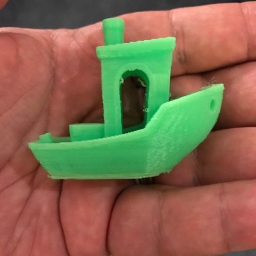
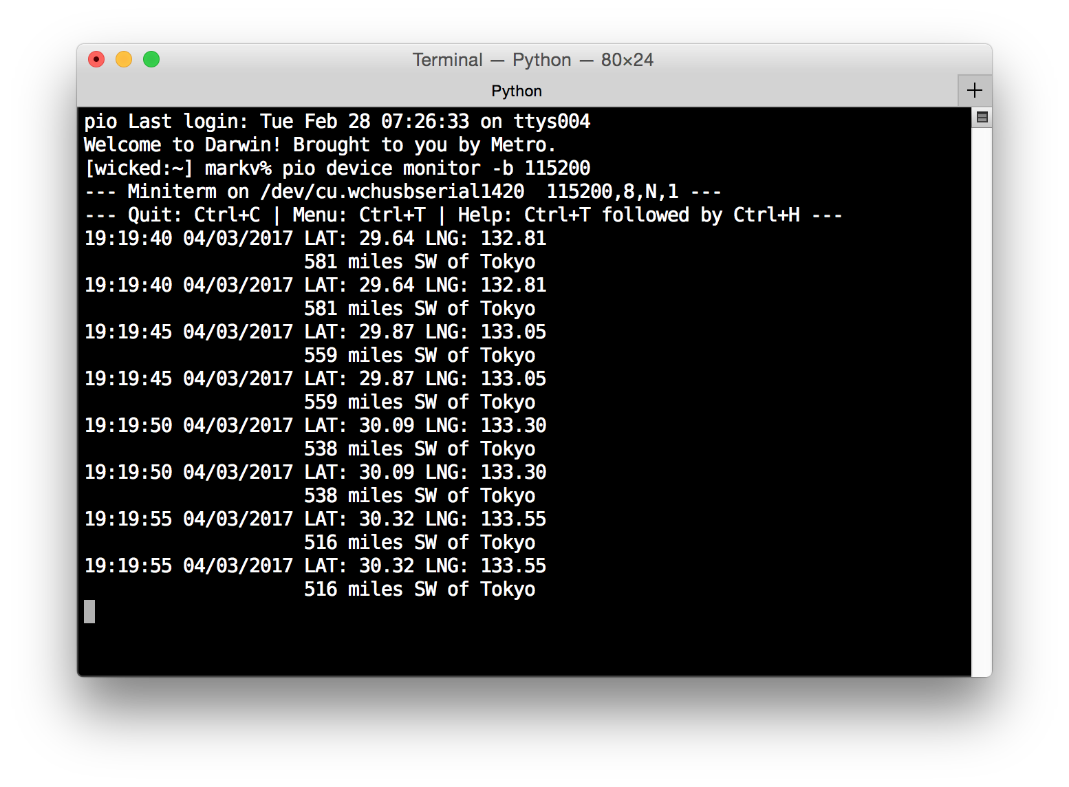
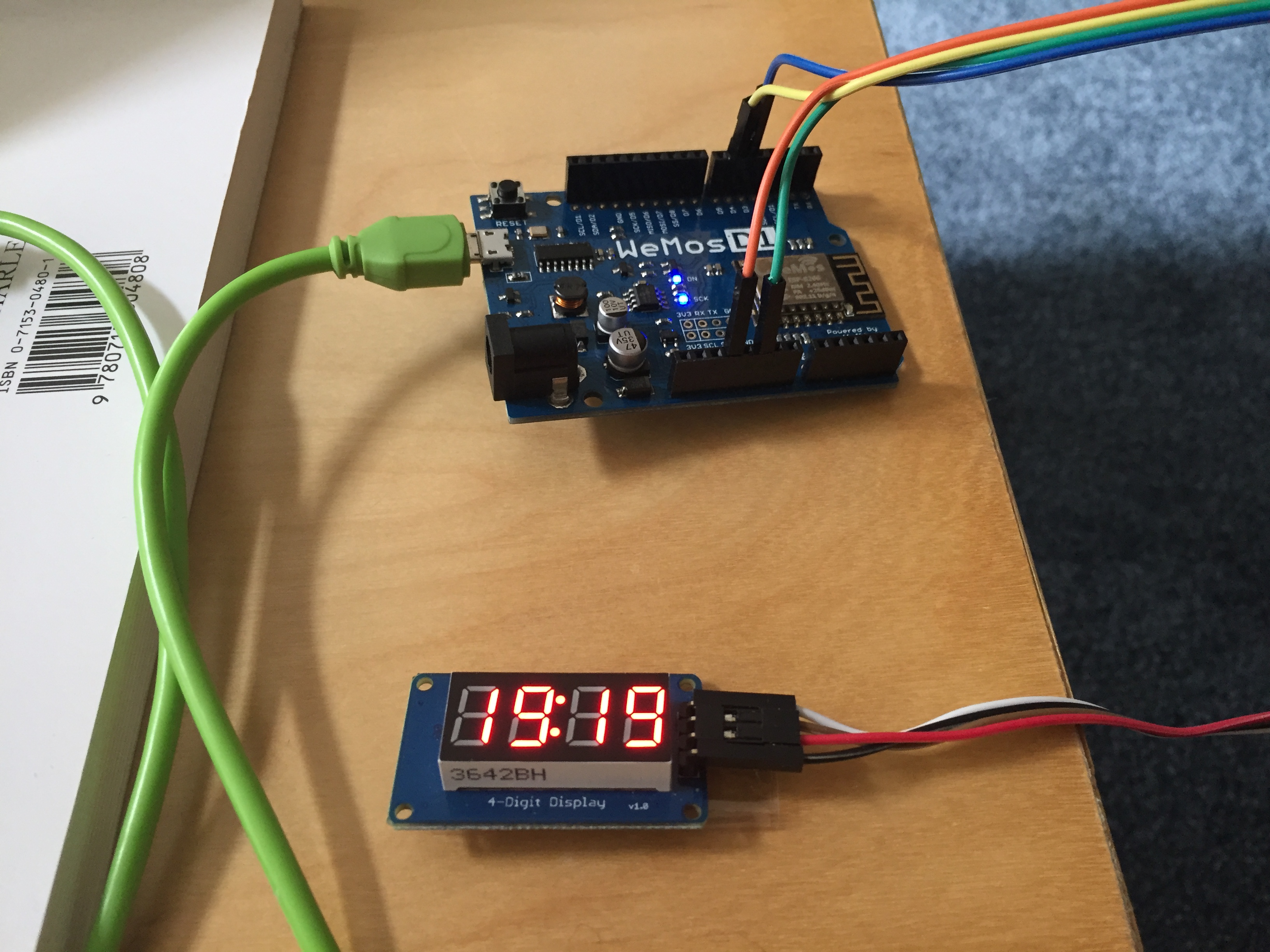
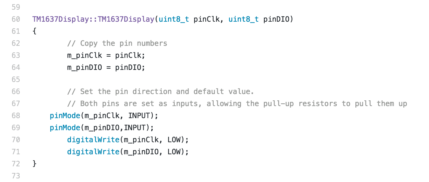
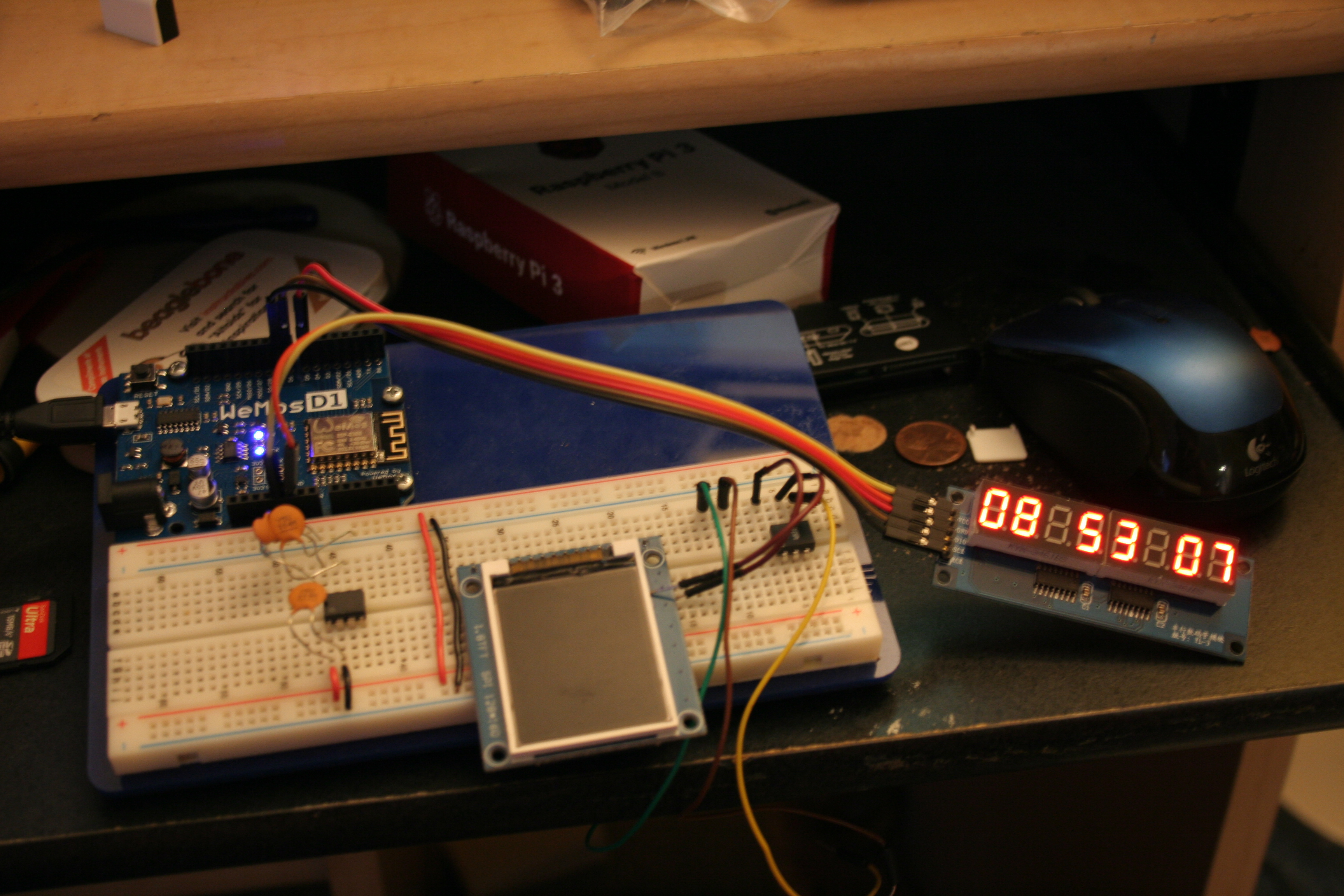
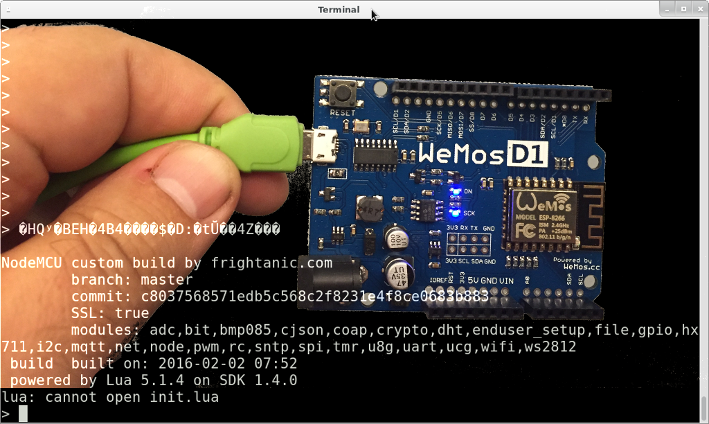
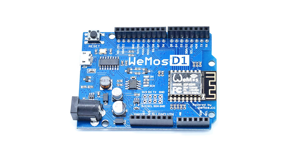
I have to say that this appealed to my ego, and as a result, it began to dig into my time that I normally would have spent on my blog, which slowed to a trickle over the last six months. It’s not that I haven’t done anything interesting and Quora is taking 100% of my time. I upgraded my soldering equipment to include a hot air rework station and a better soldering iron. I started to import lots of cool modules and stuff from China and play with them. I ordered a kit for a 3D printer and built it.

But I had stopped writing about the things that I do, and instead spent that time answering questions about stuff which mattered less to me, but which were (apparently) interesting to more people.

Over the holiday break, I began to consider where this state of affairs had led me.

Yes, it’s flattering to get comments and followers. It’s easy to add your voice in the form of opinion or indignation, and in a political environment where you feel like you need an outlet, it can be quite attractive to use easy outlets like Facebook, Twitter or Quora to vent.

But it’s not really what I want to be doing. Or at the very least, the amount of effort that I am placing in that area is out of proportion to its importance.


My blog was about stuff that I liked and stuff I was doing. It was intended to be half documentation and half inspiration. The documentation was often for me: to remind me of the stuff I had learned and might need again. The inspiration was to get others to look into the same sort of things that I like, and to come talk to me about them.

Quora doesn’t serve either of those purposes, but it is taking all of my time. So, I’m trying something new in 2018.

I’m trying to dedicate just thirty minutes of my day to do something and write about it on my blog. It doesn’t matter what it is. It might be a recommendation for a book I enjoyed. It might be projects I’m working on. It might be a review of some tech product that I found especially useful. It actually doesn’t matter what it is. It will begin with something I’m doing or thinking about, and something which I think might be worth sharing. If any of my old readers (or any new ones) find anything interesting, I’ll hope that you’ll follow my blog and comment. I’ll probably work on ways to make sure that it is as easy as possible to do so, and I might even start thinking about using a platform like YouTube to do interesting and engaging stuff. But my goal is to get back to discussing the stuff that I find fun and interesting.

I hope that you will find it so too, and come back again soon.

brainwagon.org should now redirect to use HTTPS

January 3, 2018 | Blogging | By: Mark VandeWettering

I set up a plugin so that trying to access http://brainwagon.org should now automatically redirect to use https and the HTTPS protocol.   If anybody has any difficulty with pages, drop me a quick comment here, or a note via twitter (@brainwagon) and I’ll try to see what’s up.

Coming soon: my review of Google WiFi, plus my experiences with the Anet A8 3D printer.

Happy New Year!

January 3, 2018 | Blogging | By: Mark VandeWettering

Well, I have decided to do a little well needed maintenance on the blog.  I installed an SSL certificate so my blog will now be available via HTTPS, and played around a bit with a U2F Zero dual factor authentication key.   My goal for the New Year is to try to spend 30 minutes every day working on my blog, which I am going to take from the entirely too much time I’ve spent on Quora.   Stay tuned for more stuff to come.

Some new addition to the brainwagon labs…

September 25, 2017 | 3D printing | By: Mark VandeWettering

Okay, I bet that hardly anyone comes to this blog anymore.  I’ve been slack, and there hasn’t been any reason other than the simple fact that I haven’t felt motivated to invest the time and energy to talk about any of my projects.  But that doesn’t mean that I have completely halted all attempts at doing cool (or at least “cool to me”) projects.  Over the last few months, I have:

  • started teaching myself how to use Kicad
  • ordered all sorts of crazy electronics modules from China
  • upgraded my soldering iron to a Hakko 888 and got a hot air rework station from Sparkfun
  • ordered my first boards from OSHpark
  • and in the last week, assembled a 3D printer from a $150 kit

Just as a tease, here’s my second print off my completely unoptimized 3D printer.   Not at all bad!

If any of these projects sound interesting and you’d like to hear more, why not send me a tweet (@twitter) and let me know what topics you are interested in.  I could use a little poking and prodding to increase my enthusiasm.  I still might get around to it without your questions and polite prodding, but every little bit helps.

pinMode v. digitalWrite: what’s with this use (abuse?) of internal pullups?

March 4, 2017 | Amateur Satellite, ESP8266, My Projects | By: Mark VandeWettering

This post is the kind of round about post you get first thing in the morning.   I’ll get to the title question at the end.

This morning, I was interested in doing a tiny bit of tinkering. I had found one of these 4 digit 7 segment LED displays while digging around for something else. You can get these modules for about $2.50 from banggood, and potentially for as little as a buck on eBay.

A little over a week ago, I was tinkering with a WeMOS D1 Mini board that I had acquired, and decided to port my Plan-13 library to it. Long (long long) time readers may remember some years ago that I wrote this code to predict the position of satellites, first in Python, but then ported it to C and had it running on the Arduino as part of my ANGST (Arduino ‘n Gameduino Satellite Tracker) project. But that project had a number of shortcomings:

  • It was fairly complicated, and required a number of additional add-ons to work.  I used the Gameduino to generate graphics, had an external RTC and EEPROM to store orbital data, and used an optical shaft encoder to move around.  Yes, it was attractive and fun, but not cost effective.
  • It had no easy way to update orbital elements.  You had to connect it to a PC and reprogram it with new orbital elements each time you needed an update.

But these WeMOS boards are built around the ESP8266 modules, which have a number of advantages:

  • They are based around an 80Mhz 32 bit processor, instead of a 16Mhz 8 bit processor.
  • They have 4Mbytes of flash memory.  You can easily configure some small part of that to serve as a miniature file system, ample to store orbital elements without any additional hardware.
  • They are cheap: around $5.
  • And most intriguingly: they have WiFi. 

So, I worked on the spiritual descendent of ANGST.   Using the platformio system I moved a copy of my Plan13 library to a new project, and started tinkering.   As of now, the project:

  • Wakes up and connects to my local WiFi network
  • Establishes a connection to an NTP server, so I can get the time
  • Connects to Celestrak and downloads the latest orbital elements for the ISS
  • Predicts the next three passes from my home location
  • And then enters a loop, predicting the sub-satellite latitude and longitude, its location relative to some major world cities, and if it is above the horizon, then the azimuth and altitude of the satellite.

Here is the current data as I write this:

But the one thing it did not have until this morning was an external display.  Hence, the TM1637, and a little tinkering.

Time is in GMT, but eventually I will also have it have the option of using local time (it is more convenient to use GMT for the satellite computations.)

To get this to work, I could have dusted off the work to drive the similar TM1640 based displays that I used in another project, but I thought that I’d use a standard library instead.   The platformio system has a pretty nifty library manager, so I searched for a library, found one (cool!) and it claimed compatibility with the ESP8266.  Neat.

So I read some of the example code, patched it to output the time in the main loop(), and tried it.

It didn’t work.

I double-checked connections.

It didn’t work.

I tried their example.

It didn’t work.  The displays remained dark.

Grumble.  I opened up the code and tried to see what was going on.   It didn’t take me too long to figure out what was going on:

Here is a link to the code, and a screen grab of the offending lines:

Link to the source on github

It’s not exactly my first rodeo, so I was immediately suspicious when I saw that the initializer set the mode for the two pins to INPUT, rather than OUTPUT, but then immediately wrote to them.  That doesn’t seem right, does it?

Well, this isn’t even my second rodeo.  I know that Arduino’s ATMega328 processor has internal pull up resistors, and I’ve seen odd code which used pinMode to swap back and forth between high and low, not using pinMode.

But the ESP8266 (thought I) doesn’t have internal pull ups.   I’m pretty sure that’s true, but I never got to verify it, because all of a sudden, with no change whatsoever, my program started working.

hate it when that happens. 

It’s been that kind of a week.

But it made me think about how this works.  Here is my guess, and I’d appreciate corrections.

During initialization, it sets pinMode to INPUT, and writes a LOW value to the data pin.   Even though we’ve written a LOW, the pin is pulled HIGH by the action of the (external) pull up resistor.

When the driver wishes to shift the output pin to LOW, it uses pinMode() to shift the type for the pin to OUTPUT.   When it wants it to be high, it sets pinMode() to INPUT.

I find this odd in a couple of ways:

  • It is not any shorter or more efficient than using digitalWrite.
  • It is certainly no clearer.

Is there something I’m missing about why you would code this stuff this way?

Of course, I wouldn’t have dug into this code at all had I not had a mysterious (and fleeting) failure at the beginning, so I am not sure how it really matters.

Addendum:  While I was typing this, the ISS did a 65 degree elevation pass which was captured thusly.  I only then noticed that it was producing duplicate messages for each five second message.  Must have goofed when I installed the code to blink the clock’s “colon” segments.  I’ll get it sorted later.


How making an ISS clock turns into researching an optimization problem involving spherical Voronoi diagrams…

February 20, 2017 | Amateur Satellite, ESP8266 | By: Mark VandeWettering

A few years ago, I got seriously interested in amateur radio and satellites. I would often haul out a small Yagi antenna and my trusty Kenwood TH-D7A and try to talk to other hams by bouncing signals off the various satellites which acted as amateur radio repeaters. During that time, I wrote a Python version of G3RUH’s Plan-13 algorithm for predicting satellite locations. Eventually, I converted that code to C++ and made an Arduino/Gameduino version that I called “Angst”.


But there were a number of problems with it as a general project. Most notably, it utilized some special hardware which made it more expensive than I would like, and it required an external display. I suppose I could have found a small composite display, but one serious issue remained: there was no simple way to update the orbital elements that are used to predict the satellite locations. The ISS is particularly problematic, since it is in low earth orbit and frequently fires its engines to boost it to a higher orbit, which is not something that can be accounted for statically.

But in the years since I did that project, the ESP8266 has taken the world by storm. Not only is it cheap (I got some WeMos D1 Mini clones for less than $5 shipped from China) but it is faster (an 80Mhz 32 bit processor) and most importantly includes WiFi.

For the last couple of days, I’ve been tinkering my old Plan-13 code together with some new code written especially for the ESP8266 to create a “clock” that will automatically tell me the position of the ISS and details about the next pass. The nice thing is that since the ESP8266 has WiFi, it can update itself automatically. Right now, I have code running that contacts celestrak.com, finds the latest orbital elements, predicts the next three passes, and then enters a loop where it shows the current position of the ISS every five seconds. Right now, it just echoes that information out on the serial line, but eventually I’ll get a tiny TFT or LED display to display the live information:

But just seeing the latitude and longitude of the “sub satellite” point didn’t really help me know where the satellite was in its orbit. Sure, I could (and probably will) make a little graphical display for the gadget sooner or later, but I thought it might be nice if I could have it tell me when it was passing close to certain major cities. To give this a try, I found a list of world cities and their coordinates and population, and selected the top fifty cities of the world and within the United States (make one hundred cities total) and then when I do a prediction, quickly compute the distance and bearing to each of the cities and display the closest one. And that works, and doesn’t take too much time. You can see in the run above that the closest city was Honolulu.

But, I noticed a problem.

If you imagine that the earth is a sphere, and imagine that the each city is a point on the surface which you can think of as a seed. If you collect all points on the sphere that are closest (in the great circle) sense to that point than any other seed, you end up with the globe being divided up into a number of regions, each bounded by arcs of a great circle. If you took the same computer and math classes as me, you can recognize this as a “spherical voronoi diagram”. You can read about them here where I swiped the illustration from. Here is the Voronoi diagram of the earth with seeds at each of the World Airports:

You’ll notice something: the regions are widely varying in size. If I had loaded my ISS code with these locations, it would spend a lot of time talking about how it is thousands of miles from some remote airport in the middle of the Pacific, but when it was flying over the United States, it would rapidly shift from region to region. Indeed, because population centers are often close, it might be fairly rare for it to be closest to New York City, even though it is perhaps an obvious landmark, more obvious than the smaller ones that surround it. It might also be the case that if you have two population centers which are fairly close to one another, that approaching from one side would be masked by the other city.

Ideally, we’d like a collection of cities which:

  • are well known
  • divide the globe into a number of Voronoi regions which are nearly the same size
  • and where shape of the Voronoi regions are not too lopsided, so the cities are near the center of a roughly circular region

I haven’t figured out how to do this yet, but I’m betting that I am going to use some kind of genetic algorithm/simulated annealing approach. Stay tuned.

Musing about a 2 dimensional delta robot…

February 2, 2017 | electronics, Embedded, My Projects | By: Mark VandeWettering

First of all, if anyone is still swinging by this blog, yes, I’m still alive. While I haven’t exactly been prolific in my leisure activities, they haven’t stopped entirely. I worked on some simple embedded development for the hackaday.io 1K code challenge, which you can see on my hackaday.io page, and which hopefully I’ll write up here. I’ve got some additional projects in mind, so perhaps with a little extra effort on my part I’ll be getting back to more regular entries.

One of the things that has been kicking around in my head is to “make something that moves.” In particular, I’ve long been interested in gadgets like plotters, 3d printers, laser cutters and CNC machines. A few months ago on a whim, I ordered a CNC shield and Arduino so that I could begin to think about maybe creating a project which drives some steppers around to trace some pattern. I doubt that I possess the skills or know-how to do a good job of making a real CNC machine, but I kind of liked the idea of making a plotter. I started to work on the basic mechanical design of a simple 2D gantry. But frankly, I began to balk at the idea. You need two different sets of parallel ways, which seemed large and cumbersome, and each axis is different.

At the Maker Faire I had observed some simpler setups which generally go under the name of “Drawbots”. You can see an excellent write-up here on the “Death To Sharpie” page. I liked the idea a lot: it uses two steppers and the setups for each are symmetric. Each one winds and unwinds a chain, and the pen is suspended at the intersection of the two chains. In this incarnation, the pen doesn’t even have a separate control: it is simply drug around the poster board, leaving a trail wherever it goes. Pretty cool! I must admit though, I thought his software setup (laptop + Raspberry Pi + Arduino?) was a little complicated, and I’d probably enjoy working on the control software anyway.

But I was discussing this with my constant lunchtime companion Tom, discussing catenary curves and the like, and he basically said “why don’t you just use solid arms, making a 2D analog of the 3D delta robots you see in 3D printers?”

An awesome idea! One of the cool things about constructing a delta robot is that it consists of three essentially identical pillars. Yes, the three pillars all move slightly differently, but that is really a software issue, not a hardware one. A few moments of thought and I realized that you could make a pretty spiffy 2D version, and the math would actually be pretty easy.

So, in between tasks, I worked out the necessary quadratic equations, and created this gif that will demonstrate how the motion works.

The work space is the unit-size gray square at the bottom. It is bracketed by two rails, each of length two. Each has a carriage which runs along its side, and pins one end of a fixed arm (again, of unit length) which are held together in the center by a pin, which is where the pen will be. As you drive the red and green carriages back and forth, the intersection moves back and forth. It isn’t hard to see that the pen can reach any location in the unit square at the bottom.

It isn’t quite as compact as the typical drawbot, but I can’t help but think there are some serious mechanical advantages to setting up a bot this way. It should not be very hard to create an interpreter that could run on the Arduino that would take a small subset of G code and some basic scaling and rate information, and drive a pair of steppers to create this kind of a robot. I’ve never written code exactly like this before. It should be fun.

Stay tuned.

Simple tests using the WeMos D1 R2…

August 25, 2016 | ESP8266 | By: Mark VandeWettering

I didn’t have a ton of time to tinker when I got home, but I did play a tiny bit more with the WeMos D1 R2. I got it mounted on an old breadboard that I had previously used for Arduino experiments, and then tried reflashing it with new, fresh NodeMCU firmware that I built on the cloud. That did not result in success, but I’m willing to bet that was because of something stupid I did, although what precisely that may have been is still a mystery to me. But I then dusted off some old “clock” code that I wrote for the Arduino, and tried a quick port to the WeMos. Several of the libraries that I used on the Arduino (RTClib and TimerOne) were not supported on the ESP8266, so for the moment it’s not a real time clock: it just counts in seconds, and uses the Ticker library instead. But in the span of fifteen minutes that I eeked out just before bed, I got it working:

IMG_0036

Pardon the poor quality snapshot against all the clutter on my desk.

So far, I’m having fun with the WeMos. I will probably a sketch which uses the WiFi next, and perhaps the MQTT framework.

New WeMos D1 R2 boards have arrived…

August 24, 2016 | ESP8266 | By: Mark VandeWettering

wemosI just got a trio of WeMos D1 R2 boards from Banggood this morning. I haven’t had a chance to do anything with them yet, other than power one of them on and check it for basic function, but I thought I’d give a brief review.

For those of you who maybe haven’t been tracking the ESP8266 based boards, they are basically a small 32 bit processor which run at 80Mhz and include WiFi. What’s really astonishing is how cheap they are: simple ESP-01 boards are available for around $3. These super cheap boards don’t have a lot of expansion pins, and are a little bit of a hassle to program though, since you’ll need a FTDI or similar serial cable.

The WeMos D1 R2 takes one of these modules (the tin package to the right) and mounts it with all the necessary interface logic to interface to USB. When I plugged it into my linux box, the following messages showed up in the output to “dmesg”, indicating that it had connected it to the serial port ttyUSB0:

[48095.058498] usb 1-3.3: new full-speed USB device number 7 using ehci-pci
[48095.186475] usb 1-3.3: New USB device found, idVendor=1a86, idProduct=7523
[48095.186482] usb 1-3.3: New USB device strings: Mfr=0, Product=2, SerialNumber=0
[48095.186485] usb 1-3.3: Product: USB2.0-Serial
[48095.191571] ch341 1-3.3:1.0: ch341-uart converter detected
[48095.251692] usb 1-3.3: ch341-uart converter now attached to ttyUSB0

Then, I ran “sudo screen /dev/ttyUSB0” and connected to it. It was booted into a custom build of the “nodemcu” firmware, which runs the open source language “lua”. You can read the documentation and figure out how to access many of the peripherals and libraries.

The quality of the boards seems quite high. One thing to note is that while the pin layouts and physical form factor of the boards is identical to the Arduino, the ESP8266 board supports much fewer pins. There appears to only be a single analog input, and the labeling of the digital “D” pins are somewhat odd, and it appears that multiple pins may be connected to the same input. It also appears that there are a different set of labels on the bottom of the board, which is truly confusing.

I’ll dig in a bit more when I have some time and figure out what the deal is.

Here is the link to the Banggood page for them. I found a 15% off coupon code “BG15%OFF” using the Honey Chrome plugin, so the cost for three shipped was about $16.

A new theory of dorodango…

August 22, 2016 | Dorodango | By: Mark VandeWettering

Okay, I’ve done two, with nearly identical outcomes: a fine network of relatively shallow cracks in the “capsule”, the thin layer of fine particles which encapsulate the core. I’ve been rereading various accounts on how other people make dorodango, and have noticed a couple of differences which I think I am going to test.

I suspect now that I’m being too timid in my initial drying of the core. After forming the wet inner core, you then sprinkle on relatively fine, dry dust until it won’t hold any additional material. What I was doing was then cycling this in a plastic bag, essentially drying the core very slowly, while adding additional finer and finer material. Eventually, when I did dry out this fine material, it was relatively inflexible, and as the core shrank slightly, it tension cracks. I’m now wondering if the bulk of drying shouldn’t happen while the outer skin is still relatively coarse. So, my next ball will be worked relatively longer in its primitive stage, and will be allowed to dry overnight. One account says that if it cracks, it will likely do so in the first 30 minutes of this stage.

I think I am going to ditch the soil that I purloined from Golden Gate park as well. It has a lot of faintly greasy black silt embedded in it, which is quite slick and messy. My normal backyard dirt was easier to work. I may also buy a bag of fire clay just to see what I could do with a 50/50 clay sand mixture.

Dorodango cracks again…

August 21, 2016 | Dorodango | By: Mark VandeWettering

Sigh. My second attempt has also cracked, although it is beginning to look pretty shiny.

IMG_0028

Ordered some ESP8266 boards in an Arduino form factor…

August 20, 2016 | Arduino, Embedded, ESP8266, Hardware | By: Mark VandeWettering

r2_1The ESP8266 is an amazing little processor: cheap and capable and (most interestingly) WiFi enabled. I have some of the older “nodemcu” boards that I got for about $7 each, but there are newer alternatives that include up to 4M of flash memory, and a variety of interesting form factors.

I noticed that WeMos was producing these boards which nominally have the Arduino Uno form factor. With a 15% discount coupon from banggood.com, I got three of them on order for under $16. I’ll let you know how they work out. I’m normally not a fan of the classic Arduino shape, but I do have a number of 3d printed cases and bumpers that can be used, which makes them relatively easy to mount and wire up.

If you want to program the ESP8266, you might try using platformio, which makes it easy to use both the native SDK as well as a simpler Arduino based framework. It also supports a number of other embedded architectures, including the Arduino, but allows you to use your own editor and the like to build and organize your code. Worth looking at.

FFMPEG overlay needs “repeatlast” argument…

August 17, 2016 | Video | By: Mark VandeWettering

I use ffmpeg to add some information overlays to the videos that I often upload to YouTube. I’ve documented these before, but I had a problem that arose from time to time that I never figured out: occasionally my encodes would seemingly just go on forever, and never terminate. I discovered today that this was because the use of the “overlay” filter. It apparently keeps generating frames even after the main stream has terminated, which seems odd to me, but… whatever. If you add the repeatlast argument, you’ll get what you want.

Stashed here for reference later.

[sourcecode]
#!/bin/sh
ffmpeg -y -f concat -i files.txt -movflags +faststart -aspect 16:9 -crf 24 \
-vf "scale=854:480, fade=in:0:30, hqdn3d [xxx] ; \
color=0x33669955:854×64 [yyy] ; \
[xxx] [yyy] overlay=0:416:repeatlast=0, \
drawtext=textfile=hdr:fontfile=/usr/share/fonts/truetype/ttf-dejavu/DejaVuSans-Bold.ttf:x=10:y=432:fontsize=16:fontcolor=white" \
quad.mp4
[/sourcecode]

No! My precious dorodango!

August 11, 2016 | Dorodango | By: Mark VandeWettering

IMG_1245Eek! I was getting a bit impatient with my dorodango, so I decided to leave it out in the open air when I went to work today so I could let it dry out a bit. I returned to it having dry cracks! Note to anyone attempting this: don’t be impatient. Let it dry out slowly.

On the other hand, it does still look pretty cool. I snapped this with my Canon Digital XT and did a bit of tweaking to enhance the contrast and the cracks, and frankly, it looks pretty good. I put it back in a bag and put it in the refrigerator to sit for a half hour. I’m thinking that maybe that will draw some residual water to the surface, and maybe a little more dust rubbing will polish it. I wouldn’t mind if there were some cool looking cracks in it, if the surface was smoothed out.

It’s all an experiment!

Addendum: The center of the worst crack appears to be where the dorodango was the least round. My guess is that as the tension of the drying dorodango would have been evenly distributed if it were perfectly spherical, but the defect caused the stress to bunch up and break through. It’s spent a couple of rounds in the fridge, and the smaller cracks are filling in nicely, the center of the cracking is the only part where you can feel the cracks. I’ll try a few more rounds in the fridge to see what happens.

Addendum2:

It’s beginning to take a polish, at least for a bit. A little work with some dry fine dust and a paper towel yielded this:
IMG_1246

Dorodango: Having (or rather making) a ball with just mud

August 9, 2016 | My Projects | By: Mark VandeWettering

File_000On Sunday, I started a new project which on the face of it, seems like an enormous waste of time, but if you’ve been reading my blog for any period of time, you know that wasting time is pretty much the bread and butter of my online presence, so here we go.

I’ve started work on a dorodango (????).

A dorodango is essentially a ball of mud, carefully formed into a sphere, and then covered with layers of dried dirt until it becomes a smooth, solid sphere, and then polished to a high shine.

I’m sure that some of your are blinking your eyes and wondering if I’ve gone stark raving mad. Wonder no further. It is kind of a lunatic thing to do. On the other hand, it’s also relaxing, and gives me time to think about interesting things, or just clear my mind and think of nothing at all. And, of course, the materials you need are quite literally just some dry dirt and a little water.

If you want to see some excellent examples, you can surf over to Bruce Gardner’s excellent dorodango.com website and have a peek. My example will no doubt be less beautiful, but still pretty interesting.

I began by going out to my back yard with a small shovel and a strainer I bought just for this purpose for $1 at the Dollar Tree. I went to the portion of my garden which doesn’t get regular watering, and where the ground is very dry, and scooped up a bunch of dirt, and ran it through the sieve to remove the large pieces of gravel and other organic matter, which I dumped into a cheap $1 food container. Once I had a layer a few inches thick of relatively fine material, I strained some more into a smaller container. When I felt that I had enough material to form the initial core, I added some water (probably too much) and worked it into a paste. I then formed a rough ball, squeezing out some of the (again, too much) water, and then forming it roughly into a ball, shaking it back and forth between my two hands until a relatively good sphere was formed.

I then held it over my container of dry dirt, and sprinkled the surface with this, adding some, and then brushing it off with the base of my thumb. At this stage, the core is still pretty easy to squish, and several times, cracks would form across the ball. I then added a little bit more of the dirt and wiped across the crack, and they would go away. For a half an hour, I fought the appearance of new cracks, and then they seem to stop. The surface became quite smooth, and the ball was no longer easy to compress out of shape, although I was handling it pretty gingerly. I kept adding dry dirt to it, and rubbing it gently off with the base of my thumb until the surface appeared quite dry, and dirt would no longer stick to it. Then, I put it in a ziplock bag and set it aside in my garage on top of a piece of foam so it wouldn’t create a dent. After a few hours, water will condense out on the bag and on the surface, and you extract the ball and add more fine dirt. I’m currently in the process of repeating this process until the core is completely dried out. Then, there will be more polishing to bring up the surface sheen.

Here’s a brief iPhone video I made of the ball in progress (apologies for the vertically oriented video). The texture of the ball is already quite smooth and leathery. I estimate it will take a few more days of intermittent work before I’ll begin to work on polishing it.

I’ll hopefully post a picture of the beautiful finished sphere in a week or so. If this sounded boring, consider that I did most of the work while sitting outside, watching hummingbirds and generally relaxing. I found it a great stress relief.

If you’d like to give it a try, check out these instructions on the Make Magazine website.