I picked up an Adafruit GPS module while at the Maker Faire. It’s a cool little module. I had a couple of old GPS modules: a Parallax PMB 648 and a Garmin 89, but this one is pretty nifty:
It is small.
It is breadboard friendly.
It has a one pulse per second (1PPS) output for timing applications.
It can output position/velocity information at up to 10Hz.
It has a u.FL connector external antennas.
It can be powered down by pulling an ENABLE pin low.
Lots of good features. I hooked it up tonight. My previous modules had a difficult time getting a lock inside, but this module had no difficulty at all. From a cold start, it had no problem locking. I hooked up the 1PPS output to my oscilloscope. It generates a nice 100ms positive pulse. The specifications say the timing jitter would be around 10ns. Very nice! That should be able to make a nice timebase to test the accuracy of the DS1307 module I was playing with yesterday. Data to come soon.
I mentioned in my Maker Faire wrap up post that I had spoken with Ben Krasnow, the science guru behind the Applied Science Youtube channel. If you haven’t watched his videos, by all means, go over there and give it a whirl. Between playing with chemicals, low temperatures, rockets, X rays, and electron microscope, it’s simply humbling.
He’s also a skilled woodworker, and build this rheoscopic coffee table. What is a rheoscope, you ask? A rheoscope is a device for measuring or detecting currents, usually in fluids. His table includes a spinning disk filled with a fluid that makes it easy to see the turbulence that goes on. If you go to as many science museums as I do, you’ll recognize the gadget. If you’ve tried to build furniture, you’ll recognize the craftsmenship.
This year, Ben brought some simpler fluid cells that are easier for people to construct. I cornered him and asked him what people used for the fluid that was in the cell. He mentioned that all sorts of particulates and fluids were used, including mica. I got home, and did a little web searching, and found that you could get a small container of powdered mica via Amazon Prime for under $10, so on Sunday I ordered some, and it arrived during my lunch hour. I couldn’t resist. I dumped about 1/4 of a teaspoon into a Smart Water bottle (purchased from the cafeteria) and filmed a quick demonstration.
And then recorded a longer explanatory video (only two minutes):
I suspect that the addition of some blue food coloring would enhance the contrast of the flow significantly.
Anyway, a kind of fun science fair project for a ten year old, or an aging computer scientist.
Greetings readers. I’m hopefully wishing there is still more than one.
This weekend was the Bay Area Maker Faire 2015, the 10th incarnation of an event which has become increasingly (even frighteningly) popular. I’m tempted to channel Yogi Berra, who said “Nobody goes there. It’s way too crowded.” Anyway, I got out of my house around 9:00AM, with the plan of parking at one of the offsite parking lots and shuttling in. It took me about an hour to get to the Oracle lot on 10 Twin Dolphin Drive, and there were already probably six or eight busses lined up, but probably a thousand people lined up as well. As it happens, it took slightly more than an hour to make it onto a shuttle, drive in and enter the gates. Bleh. Not the most fun, but I had a good nights sleep the night before, so I was mostly in good spirits as I entered the park.
It was very crowded. I was by myself, so I just started wandering. When I go to these things, I am mainly looking for three things:
Projects that inspire new projects.
Cool new products, especially inexpensive dev boards and gadgets for future projects.
Cool artwork that I haven’t seen before.
Sadly, I didn’t see a ton of projects that made me think of new projects, but there were a couple. I had a nice chat with Ben Krasnow who brought some low-tech versions of his excellent rheoscopic coffee table, which were just plastic cells that rotated on a lazy susan. You’ve probably seen identical gadgets in science museums. Fluid flow is always interesting. He said the instructions were already on the Make Magazine site, but I forgot to copy the url, and didn’t find it. He also said it would be in the print edition sometime soon.
I had a nice chat with Erin Tomson of Modulo Labs LLC. She’s a former Pixar colleague, who has gone off and created Modulo, a set of pluggable programmable modules that can be used to assemble modules in a tiny, secure network, without the hassle of routing jumper wires on breadboards. (In fact, a system like this would have prevented a lost hour of my time tonight, I’ll tell that story below.) It’s a very slick little system, and I’d like to see something like this take off. I can particularly see this as useful in education.
Check out her Kickstarter video.
I particularly like optical gadgets like telescopes and microscopes. My buddies Rich and Dave from the Chabot Telescope Makers Workshop were there, grinding away and answering questions about telescopes. Nice to catch up with them. They said that quite a few people came up to them and asked “So, you guys sell telescopes?” Sigh. This is the Maker Faire. If you are in the North Bay and want to learn how to build a telescope, click on the link above, and think about attending one of their free workshops (every Friday!).
I like projects which reuse camera phones, and this microscope project seemed pretty cool. They had a little gadget that allowed you to swap out three different lenses to get different magnifications. Their system seemed pretty cool, but the basic idea is pretty simple (in fact, it’s basically a version of Antonie van Leeuwenhoek’s first microscopes, but instead of holding it close to your eye, it’s held close to your cell phone, which can use nifty features like zoom and exposure adjustments, and can of course record video and stills. I should design such a gadget myself.
I also had a nice chat with Alan Yates who was demonstrating some “Lighthouse” technology that he’s been working on at Valve. The basic idea is to create a set of “beacons” that can be scattered around an environment, and a sensor that can (for instance) be mounted on a VR headset and can be used to figure out the position and orientation of the headset with high accuracy and low latency. I don’t have a link for this work yet (did I miss it, Alan?) but when I do, I’ll try to update it.
That was kind of it. I did poke my nose into various people experimenting with aquaponics, which I find interesting. I had a brief chat with the creators of Chip, the $9 computer currently on Kickstarter (I hope to have more information on that soon, stay tuned.) I didn’t spend much time in the “Dark Room”, the noise and flashing gives me a headache. I did spend some time looking at the various gardening and bee keeping exhibits.
And, I did pick up some new gadgets. Here’s a short video of my purchases, along with some links to the various items mentioned.
A Spark.io Particle Photon Kit Spark.io has changed their name to Particle, and then did a deal with Sparkfun to build additional add ons and distribute the Photon. I don’t know a lot about the Photon yet, expect some posts about it in the future.
A little wireless keyboard from dfrobot.com. Hooked it up to my Raspberry Pi in my living room, and it seems to work pretty well. DFRobot appears to have their own line of Arduino clones, including ones that do Bluetooth Low Energy at fairly reasonable prices. Might be worth checking out.
And that’s about it. If anyone thinks I missed something super cool, drop me a comment below and I’ll check it out.
Today, I had a bunch of chores to do, but I did start to play around with my AD9850 project a bit more. Since I spent so much time driving around yesterday, I had lots of time to think, and realized that the code the determined the tuning word (the 32 bit value used to select the frequency of the oscillator) was probably going to not work properly, since it used floating point arithmetic, and that probably didn’t have sufficient precision to do the calculation the way that I had coded. Indeed, when I got home, I hooked up and Arduino and found that I was not getting the sub-Hz spacing that I requested. I played around with the math a little bit, and got it working better, and then set it up and started it going. I had the output of the AD9850 going into my oscilloscope, so I could monitor the waveform.
And it was glitchy. Intermittent. Not working properly. Had I made a programming mistake?
I spent the better part of 45 minutes trying to understand how I had broken the program. Nothing made sense. I was cranky. I decided to step back and go buy some cat litter than I had forgotten, and give it a rest.
And of course when I got back, I stared at the board again. And it was immediately obvious. I had the AD9850 module on a breadboard, with all the RESET/CLOCK/LOAD/DATA lines going to the Arduino. And… that was it…
There was no common GND. I had somehow tugged out that little jumper wire. Without a common ground, it was surprising that there was any communications between the module and the Arduino.
Plugged it back in and voila. All works. Sigh. An hour of my life, wasted.
Yesterday, I mentioned the idea of using the cheap ESP8266 as a clock source for a WSPR beacon transmitter. My initial idea was to basically write code for the Arduino that connected to a remote NTP server, formulate UDP packages… sounds like a pain. But then I found that there was alternative software I could upload to the ESP8266 that would implement the NTP client on the ESP8266 module, and then simply fetch it with an “AT” style command.
So, I downloaded the firmware, and gave it a shot.
I rebooted, and then told it to connect to my local wifi network, and then told it to start the NTP client with the following commands…
AT+CWJAP="ssid","password"
OK

AT+CIPNTP=0
And it works! I can get this connected to the Arduino and write up a simple sketch, and it should be able to update the time really easily. This is cheaper and probably easier than using a GPS as a time source. Very cool.
Yesterday I finally found a copy of the code that I wrote years ago to figure out the tone sequence for messages used by the Weak Signal Propation Reporter system. To avoid losing it again, I decided to put both the C versions and the Python versions on my github page so that even if my servers go down I’ll have the code archived somewhere. If you have need of the code, feel free to use it (it would be nice if you gave an attribution in any derivative works that you distribute, but I won’t go so far as to insist).
When I got home, I found myself thinking about using the AD9850 as a WSPR beacon, using an Arduino (or similar) to generate the tone sequence, telling the AD9850 to switch to those frequencies, and generate the appropriate RF. This was basically a meld of two programs: the genwspr.c code that I listed above, and a simple sketch that can be used to set the AD9850 to different frequencies. It seemed very simple, so I sat down and started tinkering.
I began by copying the genwspr.c program into a new wspr.ino sketch. It pretty much would compile as is (after I added the necessary dummy setup() and loop() entry points needed by the Arduino) but it did not generate the same code sequence as the code did when I ran it on my desktop. A moment’s thought revealed the likely cause: “int” values are only 16 bits on the AVR. It actually took me a bit of time to get the types sorted out (maybe 30 minutes), mostly because I didn’t remember that I should use (1UL< <n) instead of just (1<<n) to get the needed 32 bit values.
Once I got that sorted out, I extracted the needed “setFrequency” routines from an AD9850 sketch, and created a loop that would send the different frequencies at the right time. The four tones needed by WSPR are 12000/8192 (or about 1.465 Hz) apart and are 8192 / 12000 seconds in duration. My initial code simply calculated the frequency for the the given message entry, sent the appropriate tuning word to the AD9850, and then called delay(8192/12) (delay uses microseconds). Because that didn’t take into account the time spent calculating and setting the tuning word, the overall message was a bit long (actually only 22ms long) so instead I did a delay(8192/12-1), and then a delayMicroseconds(22000/162). That put it right at the 110.592 seconds that are specified. (I know it’s silly, the clock in the Arduino could easily be off, but I thought it would be good to be tidy. If you had source to an accurate 1PPS source, you could do a better job of this).
I was a tiny bit concerned that the tuning resolution of the AD9850 was insufficient, but consulting the datasheet, the nominal resolution is about 0.029 Hz. That should be fine. I’ll dig out my SDR-IQ this weekend and try to do some workbench reception tests over the next few days.
The next bit you need to make a functioning beacon is to ensure that the transmissions start one second after even minutes. That requires some accurate time keeping. My initial idea was to hook up an old Parallax PMB-648 GPS module that I had lying around. During slots where it wasn’t transmitting, it could use the time signal from the GPS to ensure that the clock had not drifted. I hadn’t played with this module in a while (it’s listed as obsolete on the Parallax page) so I hooked it up to the Arduino, wrote a simple sketch to read data from it, and let it run.
Frown. It’s just not sensitive enough to get a lock while inside my house. I thought about alternatives for mounting it. Grumble. Didn’t like that idea. External antenna? Newer module? Grumble.
Perhaps a different approach was needed. I considered the various wireless modules that I had lying around. Perhaps I could use the esp8266 modules (which are really cheap) to fetch the time with NTP, and then the Arduino could use that to trigger the transmissions.
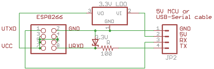
Hooking the ESP8266 to the Arduino is not quite as straightforward as the GPS because the Arduino that I use is 5V, and the ESP8266 is a 3.3v device. I have some Sparkfun level converter boards around, but it turns out that you really only need to be careful about the TX from the Arduino. The circuit below uses a little 3.3V Zener diode to drop the voltage to avoid blowing the URXD on the ESP8266. I think I have some 3.3V zeners in my box somewhere. The circuit shows a separate 3.3V low drop out regulator because the ESP8266 can be quite power hungry, and the regulator on your traditional Uno can only supply about 50ma. I believe the Redboard has a better regulator, the MICREL MIC5205 LDO can supply 150ma, so that should be fine. If I can find the Zeners, it should be easy to breadboard.
My idea was to use the ESP8266 to send out NTP packets, parse the results… but a little googling revealed a better way. There is alternative firmware for the ESP8266 that adds support for NTP directly via AT commands. If you send the AT command below, you’ll get the time back:
AT+CIPNTP?
Time: 22:22:42 12/02/2014 GMT+02
That seems awesome. The idea will be that when the Arduino is reset, it will bring up the network and try to get the time and will figure out when the next time slot begins for transmission. When that slots begins, it can decide to either transmit, or wait until the next slot. Easy-peasy.
When I get the completed sketch up, I’ll add it to my github respository.
May 11, 2015 | My Projects | By: Mark VandeWettering
Just a head’s up that I’ll be at the San Mateo Maker Faire this Saturday, May 16th. If anyone if exhibiting or attending, either drop a comment here, or email me, or just send a tweet message to @brainwagon (you do follow me, right?) and we can try to get together and say hi. I guarantee that I’m no more exciting in person than I am online, but I’d appreciate hearing what everyone else is finding cool at the Maker Faire. Hope to see you there.
May 1, 2015 | Amateur Radio | By: Mark VandeWettering
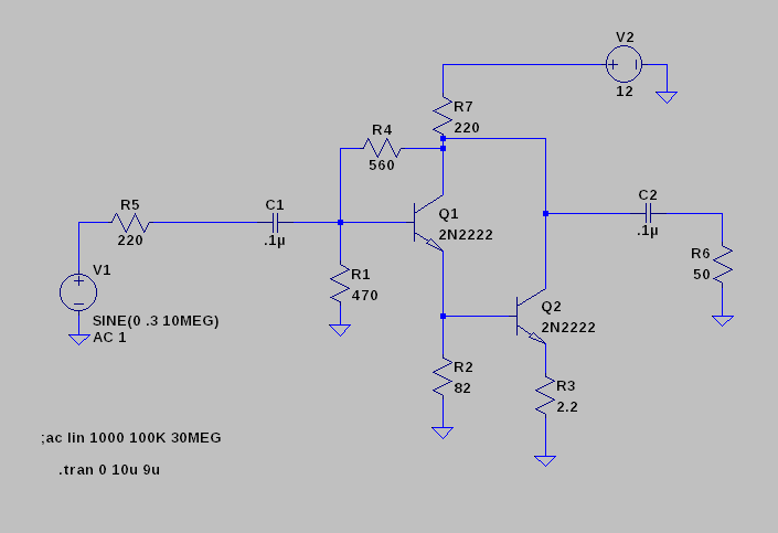
I tinkered together a circuit for a buffer amplifier that I thought would be good to use with the AD9850 DDS board I have. In particular, for the purpose of this exercise, I was trying to preserve the nice sine-wave nature of the DDS input, and present it at the output into a 50 ohm load. I dug around and ended up creating this circuit in LTSpice.
(I didn’t do the design, it was from my notes, but I failed to crib where it originally came from.)
I know it is is ridiculous to look at this from the standpoint of efficiency, but this feedback amp is astonishingly inefficient. Overall power draw averages at 470mw, with only 2.6mw of power actually delivered into the 50 ohm load. That seems pretty ridiculous in terms of efficiency.
Surely there must be a better way (power wise) to preserve the original waveform over a large range of possible output frequencies, yes? Or maybe not. I feel like understanding this is one of those teaching moments for me.
April 29, 2015 | Amateur Radio | By: Mark VandeWettering
As I’ve mentioned over the last few months, I have piles of different development boards, and lots of little display modules and the like. I’ve been thinking of doing a simple radio project, aimed at helping further experimentation with QRP (low-power) radio homebrewing. Inspired by Pete and Bill over at the Soldersmoke Podcast, I thought that I might use a dev board to build a gadget which I am calling:
The Big Box O’ RF
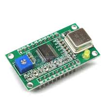
The idea is to take an Arduino (or maybe Teensy?), and connect a couple of different peripherals to it that can generate RF. I have both an AD9850 DDS module:
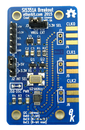
And one of Adafruit’s Si5351 boards, which are cool because they can generate three different outputs at once, under I2C control:
I also have one of Jason’s (NT7S) little Si5351 kits that I could assemble:
And of course I have a bunch of I2C display peripherals, some rotary encoders, and various power jacks. All I really need would be a nice aluminum box, and I could assemble a general purpose signal source/VFO that I could use in experiments.
Sounds pretty cool, yes?
Well, I have a few details to work out:
I’m envisioning a front panel which has a bunch of panel mount connectors that I can attach coax pigtails to route RF to my various project. (Probably 4, one for the AD9850, and three for outputs from the Si5351). The (semi) obvious choice would be SMA female panel connectors, and use pigtails to inject the RF into various other projects. Does anyone have any recommendations for where to get reasonably inexpensive SMA male-male pigtails? Is there a better (read cheaper) alternative that could be used? I’ve used Type F or even RCA jacks before, is that stupid?
Inside the box, would you use RG174 or RG316 to carry RF signals from the board outputs to the panel mounts? Any hints on shielding?
Should I make a buffer amplifier for the outputs? Or low pass filter modules (switchable?)
This project doesn’t need to be perfect, but it would be nice if it was good enough to serve as test equipment that I would want to keep on my desk. Anybody have any ideas?
Addendum: This box built by Bob, WV2YAU seems close to what I have in mind:
April 27, 2015 | Arduino | By: Mark VandeWettering
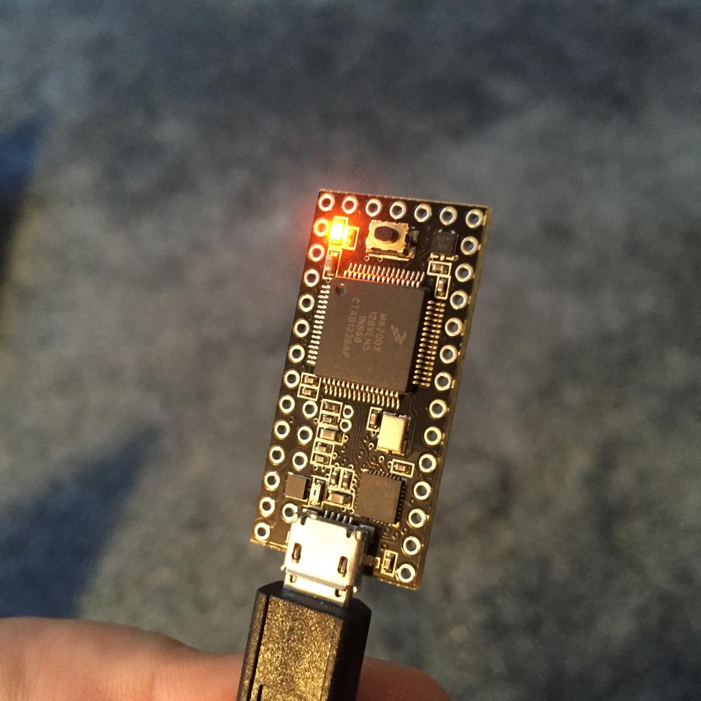
I was trying to make some headway on my robotic platform project, so I went digging through boxes in my office to find the large, 12v SLA battery that I know I have somewhere. While searching I found a bunch of stuff: hundreds of red LEDs in a pack, two Arduinos, a Sparkfun breakoutboard for an electret microphone, a bunch of level converters, and a Teensy 3.0. But of course, no battery.
So, I played a bit with the Teensy.
The Teensy 3.0 is an older version of the more modern Teensy 3.1 and the Teensy LC (which I have on order right now from Sparkfun). It’s a, well, teensy board: only 1.4″ x 0.7″ It has a 32 bit arm processor which has 128K of flash and 16kb of RAM, and a bunch of peripherals. You have to solder on your own header pins, but it would be easy to do so and put it on a breadboard. And, what’s sort of cool, you can program it pretty much exactly like an Arduino. Same setup()/loop() structure. You use pinMode(), digitalRead() and digitalWrite(). The Serial objects work the same. Pretty cool.
As a first (but not particularly challenging) test, I downloaded my Morse beacon code. It worked fine, with no changes: the Teensy even uses pin 13 to flash its tiny onboard orange led. Pretty nifty.
I’ve been pondering using Arduino Mini/Nanos for future projects, but I’m kind of viewing the ATMega328 chip that underlies those Arduinos as a bit of a dinosaur. These chips are a lot faster, and at around $13 for the Teensy LC (which has same clock rate, but only 64K flash and 8K memory) I think I may have found a better embeddable CPU for projects.
Addendum: the Teensy family is well supported with platformio as well.
April 25, 2015 | Amateur Radio | By: Mark VandeWettering
I was originally licensed under the callsign KF6KYI (Kenwood-Yaesu-Icom, or what I prefer, Kiss Your Iguana) but when I upgraded to Extra a few years back, I dug around and was lucky enough to snag the callsign K6HX (missed out on getting the highly desirable K6TT, which would have been AWESOME). I never really gave it much thought. I remember looking up the history of the call, and finding that it was previously held by something called the “Lew Stoner Memorial DX Club”, with Donald Stoner, W6TNS listed as the club trustee. Both his call and the club call (along with a second one called the Lew Stoner Memorial DX Club East W8IMS) had expired, so I hypothesized that this gentleman had become a silent key, and nobody had stepped forward to claim his call or renew the club calls.
Tonight, I dug a little deeper, and found something interesting that I did not know.
No doubt some of you are familiar with Don. He is perhaps most famous for being the guy who first dreamed of the OSCAR: which stood for Orbiting Satellite Carrying Amateur Radio. He laid out a vision for the program in a February, 1961 article for QST magazine (if you are a member of the ARRL, you can download a copy). In it, he lays out the vision of a satellite beacon, and a later satellite repeater that could be operated and worked by radio amateurs on the 2m band. It’s a very cool article, and of course now 50+ years later, amateurs achieved all he dreamed of and more. In it, he mentions that he would publish the circuit for a beacon transmitter that could be built by amateurs for “less than $15”, but as near as I can tell, that article was never published.
I was not able to find any references to “Lew Stoner” or to any activities by the DX Club which bears his name. Does anyone else know any more information?
AMSAT is excited to announce that we have accepted an opportunity to participate in a potential rideshare as a hosted payload on a geostationary satellite planned for launch in 2017. An amateur radio payload, operating in the Amateur Satellite Service, will fly on a spacecraft which Millennium Space Systems (MSS) of El Segundo, CA is contracted to design, launch, and operate for the US government based on their Aquila M8 Series Satellite Structure.
This would be very exciting. The only satellites I’ve worked have really worked with any regularity have been the FM satellites in low earth orbit. I’d love to have an opportunity to develop a station to work a bird in geostationary orbit. I’ll be watching this closely, and probably kicking in some donations to AMSAT-NA to grease the skids.
A couple of people on my twitter feed yesterday (aside: I tweet using @brainwagon, and passed 5000 tweets yesterday) had questions about how this light field camera worked, how fast the sensor was, how long it takes to acquire the image, etc… While this is the first Lytro camera I’ve ever had the time to tinker with, I did spend a couple of years doing R&D on computational photography in general and light field photography in particular, so I am pretty familiar with how these things work, and combined with information like the Lytro Meltdown and the lfp splitter, I was able to tear apart my example the files for the example “monkey” picture I took yesterday. For completeness:
So, how does the Lytro take pictures that can do this?
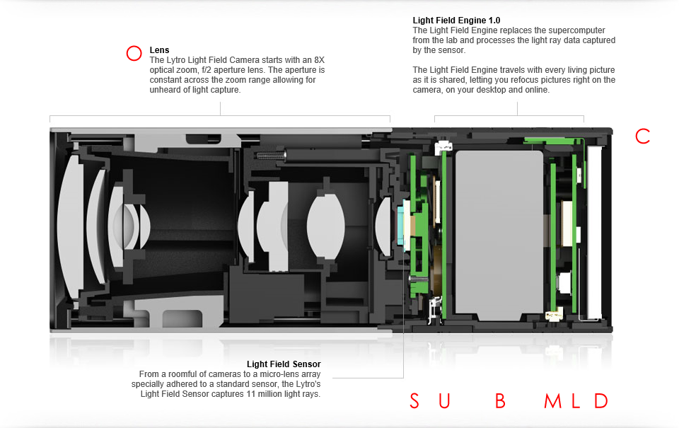
First, let’s take a look at the cross section of the camera, thoughtfully provided from Lytro on the web:
Despite it’s kind of primitive outer appearance, inside it’s remarkably complex. As someone who played a small part in the optical design of a similar camera, it can be remarkably tricky. But you might look at it and say: “Gosh, it’s a telephoto lens, big whoop! Where is the ‘secret sauce’?”
It’s in the area labelled light field sensor. Instead of having an ordinary CCD which simply samples the illumination on the focus plane at a bunch of individual locations, the light field camera has a micro lens array: an array of tiny lenses which allow the camera to not only measure the total illumination arriving at a location, but it’s distribution: what proportion of that light is arriving from each direction. It’s this property that will eventually allow the computational magic allows refocusing.
You probably aren’t able to visualize that very well (I certainly couldn’t when I began), but here’s an example which may (but probably won’t) help a bit. Even if you don’t completely get it, it’s kind of cool.
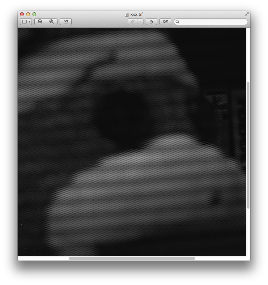
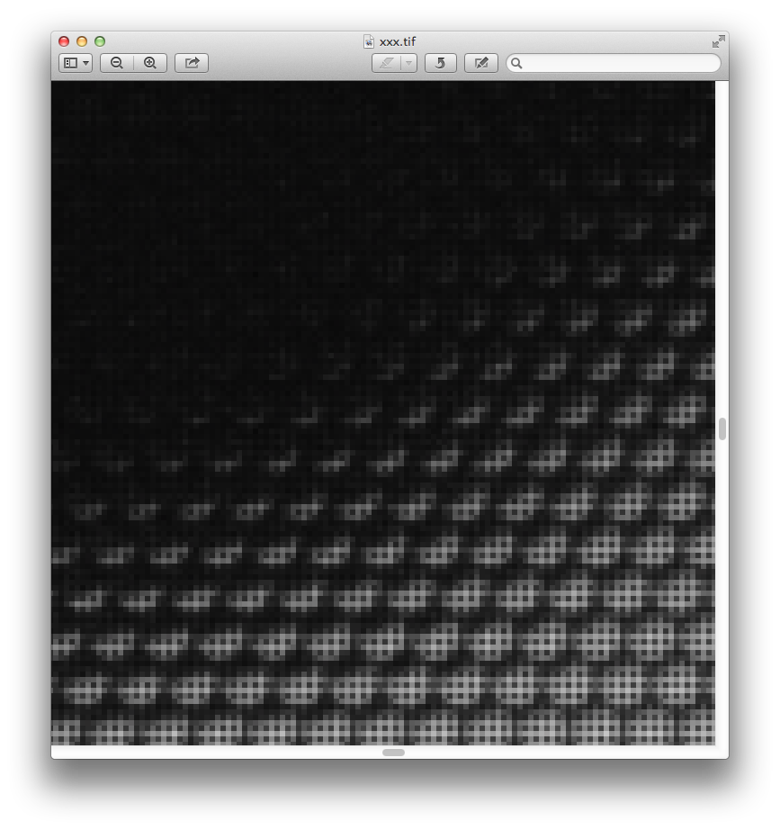
Using the lfpsplitter tools above, I extracted the “raw” pixel data from the monkey snapshot I did. If you are familiar with the way most cameras work, you might know that inside digital cameras is a sensor which can be thought of as an array of pixels. Some are sensitive to red, some green, some blue, usually arranged in an grid that is called a a Bayer filter or a Bayer mask. Software in your camera is responsible for looking at each individual R, G, and B pixel and combining them to produce RGB pixels of a resolution lower (usually by 1/2) of the native resolution of the sensor. The image below is a similar “raw” image of the sensor data coming from the Lytro. It is represented as monochrome values, each of which is 16 bits. It looks dark because all the processing of the Bayer filtering, exposure, color balance etc has not been done. The original images are 3280×3280, which I’ve shrunk down to fit on this page.
You can probably see monkey, but might ask, “again, what’s the deal? Seem just like a dark, bad image of the monkey?” Let’s zoom in.
And further?
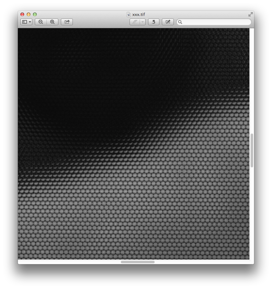
And finally down at the bottom, looking at individual pixels:
The large image is actually made up of little tiny circular images, packed in a hexagonal array. Each pixel is about 1.4 microns across. The circular images of each lenslet are about 13.89 microns across. The rectilinear “gridding” artifact you see is from the Bayer mask.
Pretty nifty.
The software that gets you from this raw image to the final image is actually non trivial, in no small part because the calibration is so difficult. But it’s awesome that I have a little gadget that can acquire these raw light fields (our prototypes were far bulkier).
Last night, I spent some time trying to understand the Wifi protocol, and wrote some code that was successful in receiving the callback messages from the camera, but had a bit more difficulty with understanding and getting the command messages to work. The idea is to create a set of Python programs that will allow me to pull this kind of raw data from the camera, without needing to go through the Mac OS/Windows Lytro Desktop software. If anyone has done this, I’d love to compare notes. Stay tuned.
April 24, 2015 | My Photos, Optics | By: Mark VandeWettering
I spent a couple years of my life working on a light field motion picture camera (and got named on two patents) as part of my former work, so I’ve been interested in light field photography and computational photography more generally. The company Lytro was basically the first to market such a device, and recently they were discontinued. Because of that, they were pretty cheap on woot.com, and I couldn’t resist picking one up. It arrived today.
Here’s my first picture. Try clicking on it in various places, or clicking on it and dragging a bit.
I may do a video review of the product, not so much as a product, but basically as an introduction to light field photography, which I still think is interesting, even though the technology isn’t quite their yet.
Stay tuned.
Addendum:The Lytro Meltdown site documents the Wifi protocol for the camera, which means that I might be able to hack together some python code to extract the images from the camera. I might use the Raspberry Pi to experiment. Basically, the camera creates a private wifi network, which you can connect to. Once on that network, you connect to the camera and issue commands over special ports, in a bizarre format. Why they didn’t choose to use HTTP? That’s why the product is no doubt discontinued.
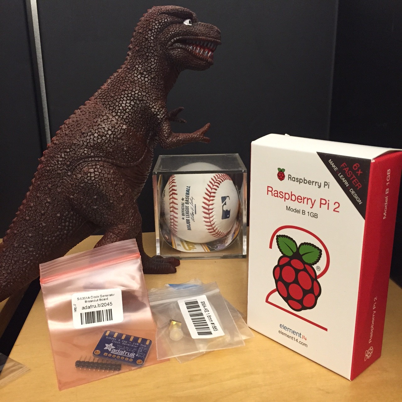
I think Bill and Pete have been having way too much fun with the radio projects centered around the Arduino and the SI5351, so I decided to join them and ordered one of Adafruit’s SI5351 boards (I still have the kit from Jason’s Kickstarter which will almost certainly be better once I get up the nerve to do a little surface mount soldering). At the same time, I noticed that Adafruit had the new quad-core Raspberry Pi 2 boards in stock. It’s likely that my hummingbird cam may be resurrected onto this board to give me a little extra CPU oomph.
Oh, and the other items? I like to have plastic dinosaurs in my office, and the baseball was a ball I caught during an (otherwise completely forgettable) Oakland Athletics game.
I was informed by email that Pete was unable to achieve the same minor level of success that I had following my directions on how to get the Arduino 1.6.3 environment working with the I2C LCD display. For now, Pete seems content to use the 1.0.x versions, which I suppose is okay, but maybe we will revisit this sometime in the future. In the meantime Bill has had greater success in getting his Si5351 board working as a VFO/BFO, and has it mounted on some copper clad. Looks very nice. I should do a project like this.
Anywho… today’s aquisitions will likely show up in a future post/video. Stay tuned.
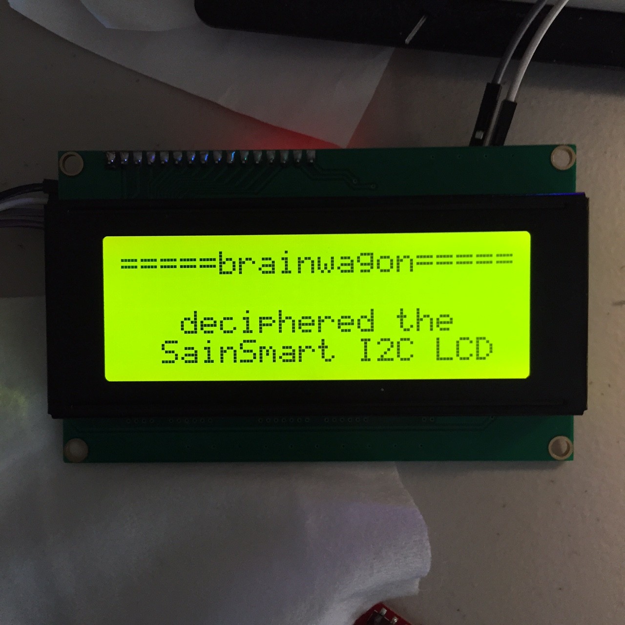
Yesterday I experienced some frustration with the SainSmart I2C LCD Module that I bought to help Pete and Bill uncover the problems that they’ve been having. If you go and read, you’ll find that I had a lot of difficulty finding the right combination of code that can be used with this module. Eventually, I figured out how to use it, so I thought I’d document it here, to avoid the pain that someone else may feel.
The basics are essentially this:
The LiquidCrystal library that ships with I2C is probably fine for connecting to LCDs with a parallel interface, but it does not support I2C bus displays.
There is a so-called “New” or “FM” version of the LiquidCrystal library that you can find documented here. You can download the code by clicking here. I tested LiquidCrystal_V1.2.1.zip while typing this up.
The new library is viewed as a replacement for the existing library. That means that you have to delete the existing library from the 1.6.3 libraries directory, and add the LiquidCrystal library in its place. This is kind of a pain, and is the worst part of this procedure. The instructions are here, but not very explicit. The commands you type also vary a bit with what operating system you use. Basically, the idea is to find the directory where the Arduino system libraries are installed, and delete (maybe after backing up) the LiquidCrystal directory, and replace its contents with the new LiquidCrystal directory. You’ll have to shutdown and restart the Arduino IDE after making the change.
And, you are almost home. You’ll have to make a couple of small changes to your sketches to make them use the I2C LCD display. Instead of including “LiquidCrystal.h”, you’ll need to include “LiquidCrystal_I2C.h”. And, you’ll need to make a small change to the “constructor” that builds the LCD object.
#include "LiquidCrystal_I2C.h"
#define BACKLIGHT_PIN (3)
#define LED_ADDR (0x27)  // might need to be 0x3F, if 0x27 doesn't work
LiquidCrystal_I2C lcd(LED_ADDR, 2, 1, 0, 4, 5, 6, 7, BACKLIGHT_PIN, POSITIVE) ;
And then you should be able to use the “lcd” object just like any other. If you look at this page, you can see all the operations that the lcd object supports. If you ever want to use (say) a parallel interfaced LCD, you’ll probably be able to do so by just changing the include and the constructor.
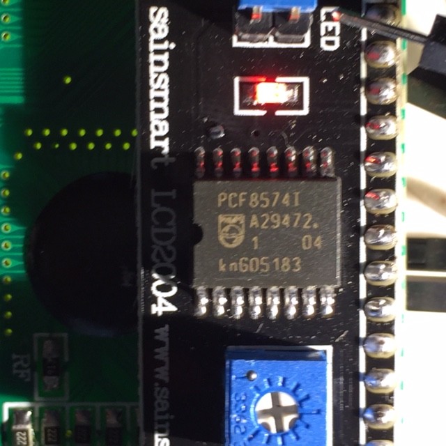
Bonus explanation: You are probably asking “what’s with all that the numbers in that constructor?” and “why those numbers?” and “what do they mean?” Here’s the basics (the details are not that important). The “piggyback” board that we use is mostly a chip that we call an “I2C I/O expander”. If you look carefully, you can read the part number off the chip. In this case, it says that it’s a PCF8574. A little Googling will reveal that it’s a chip made by Texas Instrument, and it basically has a set of data pins that can be individually configured as inputs and outputs, and read and written by commands sent over the I2C bus. The little backpack connects each one of those outputs to a particular pin on the LCD board. The library (you can think of it as a driver) is basically the code that knows how to send commands over the I2C lines, that causes each of the eight or so pins on the PCF8574 to go high or low, and thereby activating functions on the LCD.
There are a couple of complications that can arise. First of all, while the PCF8574 is a common chip, there are similar backpacks you can buy that might use different (but similar chips). If your backpack doesn’t have a PCF8574 on it, you may find that my code above doesn’t work, and you’ll have to figure out what’s happening on your own.
But even if it does, there appear to be incompatibilities between some backpacks as well. As I mentioned before, some appear to have the address 0x27 (like mine) but some might have the address 0x3F. I’m not sure why that may happen (perhaps they are using a “work-a-like” chip whose real only difference is the I2C Address it response to?)
But the major problem is that even if they use the same chip, they need to wire the circuit to the LCD in the same way. I’ll try to explain. Let’s say the I/O expander has 8 output pins, which we will label P0 through P7. They all have similar capabilities. To drive the LCD parallel inputs, we need to wire them up. One of the LCD pins controls the backlight. Which of the I/O expander outputs should we wire to it? It’s actually arbitrary, we could pick whatever we like. But to turn on the backlight, we need to know which choice was made (which of the P0-P7 we need to turn on), and the same goes for all the other pins that we need write. Thus, the software needs to know how the wiring of this little backpack is setup.
And sadly, it appears that there might be different boards, with different wiring. Luckily, in this new LiquidCrystal library, they foresaw this eventuality, and allowed you to specify how those things are wired up. If you look in the file LiquidCrystal_I2C.h, you’ll see a definition for the constructor that we are using:
This looks a bit daunting, but what it means is that you can specify an LCD panel by specifying a bunch of values. The uint8_t is just an ugly shorthand for a small integer (an unsigned value, ranging from 0-255). The first argument is the I2C address (0x27 in the case of my board). The next arguments are which I/O pin on the I/O expander goes to the named pin on the LCD board. For example, in our case, the next argument after the address was a 2. That means that P2 of the I/O expander is wired to En (the enable pin) on the LCD board. Similarly P1 goes to the Read/Write Pin, and so on. The final two arguments say that the backlight was wired to P3, and that it’s polarity is POSITIVE (some displays have the LED turn on when the pin goes to ground).
So, how did I figure out which pin goes to which? If you had a schematic for the board, you could work it out using datasheets. I actually got lucky, and realized that the example sketch on the SainSmart product page had an example sketch which included these lines. The code they posted there is not compatible with the 1.6.3 IDE (sigh) but the information was helpful.
So, it took WAY too much time, and WAY too much work, but I have it working. Hope that helps someone else who comes along later.
I’m Mark VandeWettering, former senior technical director for Pixar Animation Studios, and (for the moment I’m a husband and father and grandfather. I like telescope making, radio, and all sorts of other things.
Latest Comments
I recall burning three or four weeks of a sabbatical getting Saccade.com on the air with Wordpress. So much tweaking…
I move my pretty useless blog to Hugo about 7 years ago, since I got frustrated at too many security…
Something I used to good effect for a while was a "Pocketmod". You take a single page, fold it a…
Bloat is a serious problem, to be sure, but I'm not aware of many modern programming languages that avoid it.…
I'm running static pages (Notepad++) and a couple instances of Wordpress, and an instance of dokuwiki, all on ubuntu on…


I recall burning three or four weeks of a sabbatical getting Saccade.com on the air with Wordpress. So much tweaking…