A day at the Official Propeller Conference

May 5, 2013 | electronics, Microcontrollers | By: Mark VandeWettering

Even casual readers of this blog know that I’ve enjoyed playing around with the Arduino and the Atmel AVR chips. I really like them, and have used them for a variety of personal projects, as well as using them for a variety of educational projects for a local high school where I mentor students. But I also have a variety of other boards, from MSP430s to the BeagleBone, from the Raspberry Pi to the Parallax Propeller.

The truth is, I haven’t done a lot with the Propeller board. I must admit that a lot of it is simply inertia: if something you already know fairly well serves your needs, then learning something new is often a distraction from your task at hand. But there are things about the Propeller that I do find interesting and compelling.

It’s fast. The chip can be clocked up to 80Mhz, and has 8 cogs, each a 32 bit core with 2KB of local storage for instructions and data.

It has a built in byte code interpreter for SPIN, a high level language. Each cog can execute about 80,000 of these high level byte codes per second, or about 640,000 max if all cogs are funning. I have mixed feelings about Spin, but it’s a cool idea nonetheless.

It avoids interrupts, preferring to use cogs to process events. Interrupt processing is challenging for new programmers (and in some cases, even experienced ones) and the cog model might be easier and more flexible for many real time tasks.

It avoids dedicated hardware peripherals, instead providing “virtual” peripherals as software. Because the chip is fast, and there are many cogs, it’s possible to implement many devices such as UARTS, PWM, servo drivers and even video as code which runs on a particular cog in parallel with the user program. This gives the programmer a great deal of flexibility. SPIN supports a library of user-contributed objects which can really lend to the flexibility of the Propeller.

So, there is lots to like! So, for the second year in a row, I’ve shuffled off to meet some of my friends from tymkrs.com at the Official Propeller Conference. It’s a fairly small get together of Propeller enthusiasts, hosted by Parallax and featuring short presentations on Propeller hardware and software techniques. I had a lot of fun. Parallax is a remarkably small company, run by Ken and Chip Gracey, and having maybe forty employees. Besides the Propeller, they manufacture a bunch of other items, including sensors and robotics items. The highlight of the day was a talk by Chip about the upcoming Propeller 2. Chip’s talk was remarkably informative, and so devoid of normal marketing bull that I actually blinked several times at his honesty.

Propeller 2 looks very cool. To me, the most exciting thing is that it one ups the flexibility of the Prop 1 in allowing any pin to be configured as digital or analog, and an input or output. The Prop 1 has been used by hams to directly generate beacon signals but the new capabilities would seem to open a variety of demodulation as well as modulation techniques. Chip said that the first actual silicon for the Prop 2 will be arriving at Parallax this Monday, and that he’ll let us know via the Parallax forums how that goes. I’ll be paying attention.

I had a great time, culminating with a BBQ dinner with Atdiy, Whisker, Roy, Joe, and some of the Parallax crew. It’s inspired me to actually dig in and start learning Spin. I’m staring over at my Parallax board, happily blinking LEDS. It’s a start.

More details on the Propeller as I goof around.
Neat little beacon using an 8 pin Atmel AVR…

April 28, 2013 | Amateur Radio | By: Mark VandeWettering

Previously, I have read about a wireless Morse thermometer designed by Steve Weber, KD1JV. I played around with the basic idea in a YouTube video I made. It basically powers a little Colpitts oscillator from an IO pin on an Arduino. Weber’s circuit did much the same, just using a small 8 pin AVR and a temperature sensor to send the current temperature via Morse code.

Over on the Open Emitter blog (sorry, don’t know whose blog this is) there is a twist on this basic idea: instead of using a separate oscillator, use the oscillator that drives the microcontroller as the emitter (probably of just a few microwatts into a short wire antenna). To on-off key the oscillator, the Atmel chip is put into power-down mode, and woken up via the watch dog timer. I think it’s a cool idea, and worthy of experimentation. I’ve got some ATTINY85 chips on sale (just $1.10 each) which will probably be breadboarded into a test circuit, using either some of my 10.140Mhz crystals or maybe some of the 80m or 20m crystals that I have lying around.

Check out the article:

Tiny Beacon

Bill, N2CQR uses my Morse-sending code for the Arduino…

April 21, 2013 | Amateur Radio | By: Mark VandeWettering

I’ve been busy lately, and have done almost nothing radio related. But John was kind enough to point out to me that Bill, N2CQR of Soldersmoke fame had posted a mention of me, and I surfed over to his blog to have a peek.

His post that apparently uses my code to send Morse which is tracked by the Reverse Beacon Network

Awesome. It’a actually pretty gratifying to see how often this simple (at least for me) code has been used and reused by people. I think of this code as being almost too trivial to worry about, but it’s clear that there are lots of people who are using the Arduino to try to get into some very simple code and electronics projects. I think that’s awesome! There are a number of authors/technocrats/philosophers who are saying that those who don’t learn to write programs are simply going to be left behind: appliance operators in life, and that those that do will be able to achieve. I don’t know that it’s true, but I do think some passing knowledge of programming can be leveraged into cool projects, and I’m glad to see that Bill has taken his first steps into the world of Arduino, and glad that I could be a part of it.

Addendum:

You can get my code from this blog post.

I made a couple of different videos using variations of this code. I was inspired to make this video after seeing Steve Weber’s “Temp2Morse” project, which basically keys a small oscillator powered directly from the pin of an ATTINY processor (in his case) or an Arduino in mine.

I used another variation of this code to interface a PS/2 keyboard to the Arduino, and then used it to key my FT-817:

(Apologies if you all have seen these before, but I thought they might be new to some of you.)

Apologies for the lack of updates…

April 14, 2013 | Amateur Radio | By: Mark VandeWettering

Tap… tap… tap… Is this thing still on?

Apologies to my loyal readers (reader?) for the lack of recent updates. A combination of work pressure, family visits, general lassitude and other distractions have caused the writing muse to flee, and every time I sit down to write something down, I have just felt physically tired and unable to write stuff down. But the good thing is: the days are getting longer, my project at work is shipping, and I’m hoping that May will mark the beginning of some good new projects.

Some things I have in the works:

  • A number of Raspberry Pi related projects. In particular, I’ve got most of the parts for a little robotic platform that will carry a Raspberry Pi and a webcam. It’s my first real complete homebrew robotics project, which is kind of cool.
  • I’ve been experimenting with 3D printing, and hope to do some more.
  • Weather is improving, so the urge to get my RC airplanes back in the air.
  • I need to get back to some radio projects. I was up to 43 states on my WAS via JT65, it would be great to polish that off this summer.

Stay tuned!

My Arduino bumper, with actual prints!

March 23, 2013 | 3D, 3D printing, Arduino, My Projects | By: Mark VandeWettering

Okay, our Replicator 2 went back online this week, and I decided to give printing my Arduino bumper another try. Since the last time, I have revised the program and code a couple of times. I was concerned that the various bits of solder protruding from the bottom of the board would need extra relief cuts. As I tried to account for more and more of these, I decided I did not like the design especially well, so I took a different tactic: I decided to make the bumper’s walls as thin as possible, and only include an area around each of the Arduino bolt holes. This minimized the amount of material needed, and also means that it could be printed more quickly.

And so, I printed it out. I use the Makerbot software, set for the Replicator 2, once using medium quality (with a print time of about sixteen minutes) and once using the high quality (print time of nearly an hour). I used 25% infill for both, I wanted to make sure the outer and inner shells were sufficiently bonded. I then printed it!


I had a little spare time, so I also decided to print out a simple model I made in OpenSCAD: a cross section of the Clark Y airfoil, with 1/8″ thickness. It turned out rather well, fairly smooth, and with only a minor divot at the trailing edge. It was also reasonably sturdy, I don’t think I could crush it in compression with my hand, although it’s impact resistance is unknown. I also took the time to download a model of the chicken from Minecraft and print that. It comes in four parts, which we could then glue together. I had no real failures:


But there were a few issues.

First of all, my Arduino bumpers were a pretty tight fit.

I coded in a clearance of 0.008″ around the nominal board size, but that was simply not enough. I think I’ll expand that to 0.012″ or even 0.015″ next time around. I was able to press fit one of my OSEPP Arduino boards into it, but just barely, and only by shaving a small amount off one corner of the board with an Exacto knife. I also think I should thicken the bottom slightly: if you used this shield to bolt against a conductive surface, some of the solder joints on the bottom of the board could still short out. I am also thinking of widening the channels cut for the USB and DC jack a small amount, they fit, but just barely. An additional 0.02″ of an inch would make them more comfortable. I also noticed that one of the prints had a corner which seemed to pull up and not be level/coplanar with the rest of the print. Not sure what that was about. But overall it worked! I’ll make these changes to the design, and then try another set of prints, and then you should be able to see it on Thingiverse.


I also printed this model of the chicken from Minecraft. It comes in four parts (body, head, two feet) which you can assemble and paint. The model is quite simple, I printed it with medium quality settings and 10% infill. It worked rather well, except that the parts do not assemble easily: the head is slightly too wide to fit into the slot in the body and the feet do not fit into the holes left in the bottom. I think a little judicious belt sanding will make the head fit, and I’ll measure and redrill out the holes to make the legs fit. But in general, the issue of clearances seems to be one I need to explore more. Does anyone have any good references/hints/guides they would like to share?

Another stab at an Arduino bumper…

March 9, 2013 | Arduino, My Projects | By: Mark VandeWettering

Earlier this week, I tried to print out the first version of my Arduino bumper. Sadly, our Replicator 2 had a malfunction mid print, and it’s still offline (a problem with the temp sensor) but that doesn’t mean I’ve been entirely stationary. I mentioned on twitter that I was having trouble using the minkowski operator to generate interior offset surfaces, and @kitwallace responded this pointer to some code he used which helped me generate a “lip” inside the outer wall that would snugly fit the Arduino. I also realized that this wall would bump into the backside of some of the pins, particularly around the DC jack, but also on the ICSP and header pins. So, I revised this a bit, and came up with this program:

[sourcecode lang=”cpp”]
module arduino_outline() {
polygon([[0, 0],
[0, 2100],
[2540, 2100],
[2600, 2040],
[2600, 1590],
[2700, 1490],
[2700, 200],
[2600, 100],
[2600, 0]]) ;
}

px = 2505.512 ;
py = 1198.031 ;

module icsp() {
translate([px, py-200, 31.25]) minkowski() {
cube([100, 200, 62.5]) ;
cylinder(r=50) ;
}
}

eps = 0.001 ;

s = 25.4/1000. ;

cl = 8 ;
th = 62.5 ;

module os() {
linear_extrude(height=250)
minkowski() {
arduino_outline() ;
circle(r=th+cl) ;
}
}

module is() {
translate([0, 0, -eps]) linear_extrude(height=250 + 2 * eps)
minkowski() {
arduino_outline() ;
circle(r=cl) ;
}
}

module final() {
difference() {
os() ;
is() ;
}
}

module neg() {
union() {
intersection() {
minkowski() {
difference() {
translate([-200, -200, eps]) cube([3000, 3000, 62.5]) ;
os() ;
}
cylinder(r=200+th+cl*2) ;
}
os() ;
}
final() ;
}
}

module holes() {
union() {
translate([550, 100]) cylinder(r=125/2., h=500, center=true) ;
translate([600, 2000]) cylinder(r=125/2., h=500, center=true) ;
translate([2600, 300]) cylinder(r=125/2., h=500, center=true) ;
translate([2600, 1400]) cylinder(r=125/2., h=500, center=true) ;
}
}

off = 31.25 ;
d = 31.25 ;
w = 31.25 ;

module relief() {
translate([1100, 100, 62.5]) translate([-w, -w, -d])
cube([1400+2*w, 2*w, 2*d]) ;
translate([740, 2000, 62.5]) translate([-w, -w, -d])
cube([1740+2*w, 2*w, 2*d]) ;
}

module slots() {
union() {
translate([-100, 125, 63+off]) cube([550, 350, 500]) ;
translate([-250, 1275, 63+off]) cube([625, 500, 500]) ;
translate([-cl, 125, 0]) cube([450+cl, 350, 500]) ;
}
}

$fn = 24 ;
scale([s, s, s]) difference() { neg() ; holes() ; slots(); relief() ; icsp() ; }
[/sourcecode]

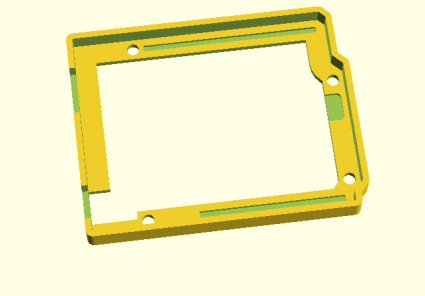
Here’s a quick picture:

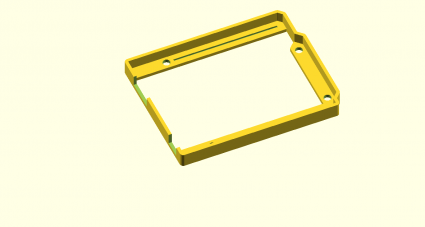
bumperv2

It might be a few days before I can get this printed. If anyone uses this to generate STL and print it, I’d love to hear about what you think.

If not, stay tuned. I’ll get there eventually.

Arduino Bumper Shell, created with OpenSCAD

March 2, 2013 | Arduino, My Projects, Raspberry Pi | By: Mark VandeWettering

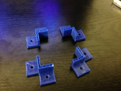
bracketsLast week, I got a chance to experiment with a Replicator 2, and printed some brackets for my robot project. I designed them using OpenSCAD, which is kind of a scripting language for solid shapes. It can export in STL format, which I then used MakerWare to drive the Replicator 2. The picture at the right shows my first attempt, which aborted when my silly laptop went to sleep. Still, the brackets worked out pretty well. The holes in the bracket were coded to be 0.125″ in diameter, which is a loose clearance hole for #4 hardware. The resulting brackets actually were close to tap size: I could thread a screw into them, but not push one through it. That seemed like a pretty good test.


bumperWhile digging around for new stuff to make, I saw a “bumper” style case for the Arduino on Thingiverse. I thought that might an interesting project, and I needed something like this to mount my Arduino onto the robot platform I’ve been working on. In about an hour, I coded up one:

[sourcecode lang=”cpp”]

module arduino_outline() {
polygon([[0, 0],
[0, 2100],
[2540, 2100],
[2600, 2040],
[2600, 1590],
[2700, 1490],
[2700, 200],
[2600, 100],
[2600, 0]]) ;
}

module edge () {
difference() {
minkowski() {
arduino_outline() ;
circle(62.5) ;
}
minkowski() {
arduino_outline() ;
circle(8) ;
}
}
}

module bands() {
minkowski() {
square([2600, 200]) ;
circle(10) ;
}
minkowski() {
translate([0, 1900]) square([2600, 200]) ;
circle(10) ;
}
minkowski() {
polygon([[2600, 1590],
[2700, 1490],
[2700, 200],
[2600, 100],
[2500, 200],
[2500, 1490]]) ;
circle(10) ;
}
}

d = 31.25 ;
w = 16 ;

module bumper() {
difference() {
union() {
linear_extrude(height=250) edge() ;
linear_extrude(height=62.5) bands() ;
}
union() {
translate([550, 100]) cylinder(r=125/2., h=500, center=true) ;
translate([600, 2000]) cylinder(r=125/2., h=500, center=true) ;
translate([2600, 300]) cylinder(r=125/2., h=500, center=true) ;
translate([2600, 1400]) cylinder(r=125/2., h=500, center=true) ;
}
translate([-75, 125, 63]) cube([525, 300, 500]) ;
translate([-250, 1275, 63]) cube([625, 500, 500]) ;
translate([1100, 100, 62.5]) translate([-w, -w, -d]) cube([1400+2*w, 2*w, 2*d]) ;
translate([740, 2000, 62.5]) translate([-w, -w, -d]) cube([1740+2*w, 2*w, 2*d]) ;

}
}

scale([25.4/1000., 25.4/1000., 25.4/1000.]) bumper() ;
[/sourcecode]

I haven’t had the chance to print it yet, so it might not be exactly right for fit, but I’ll let you know how it works out.

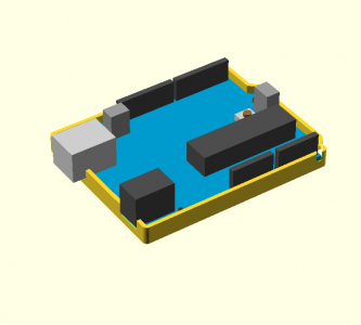
Addendum: I found a model for an Arduino in OpenSCAD, and tried merging it with my bumper. That revealed that I had made a mistake in the code listed above: the DC connector should be 350 mils wide: the slot as coded would be too narrow. I also decided to widen the relief channels for the pins which stick out the bottom, and provide an extra depth relief to support the DC and USB jacks. When I get a chance to print this out, I’ll probably upload the kit-n-kaboodle to thingiverse once I’m happy with it.

Until then, here’s the tease:

witharduino

Addendum2: I experimented a bit with export options. I projected the bumper down to 2D, exported it as DXF, and then imported it into Inkscape, where I could convert it to a 300dpi bitmap. Voila.

path3391

PIR sensor from TAUTIC.COM

February 23, 2013 | Arduino, My Projects | By: Mark VandeWettering

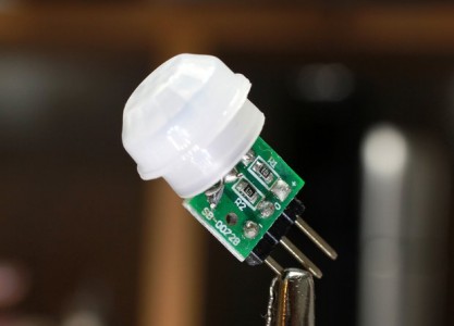
pirA few days ago, I heard that Jayson Tautic (@tautic), manufacturer and purveyor of a interesting electronic prototyping goodies, had put up an interesting offering: a small PIR (passive infra red) motion detector. I’m always up for a new sensor to play with, so I ordered a pair for fun, and they arrived on Friday.

It’s a cute little package, much smaller than I expected, about 8x10mm. It has three pins, but didn’t come with a datasheet. Some queries among my buddies on the #tymkrs channel on afternet turned up this datasheet which appears to be the part. That was good enough to sort out the pinouts: the pin labeled + is the supply voltage, the pin on the opposite side is ground, and the middle pin is the sense pin. When the sensor detects motion, that pin goes high, and remains so for two seconds after the motion halts. And that’s about it.

It was tremendously simple to wire it up to an Arduino for testing. I wired the sense pin to pin 8, and then used this simple sketch…

[sourcecode lang=”cpp”]
const int pin = 8 ;
const int ledPin = 13 ;

void
setup()
{
Serial.begin(9600) ;
pinMode(pin, INPUT) ;
pinMode(ledPin, OUTPUT) ;
}

void
loop()
{
Serial.println("NO MOTION DETECTED") ;
digitalWrite(ledPin, LOW) ;
while (digitalRead(pin) == LOW)
delay(100) ;
digitalWrite(ledPin, HIGH) ;
Serial.println("MOTION DETECTED") ;
while (digitalRead(pin) == HIGH)
delay(100) ;
}
[/sourcecode]

It will turn on the LED wired to pin 13 when motion is detected, and also prints a message to the serial port. Simple.

I haven’t done any testing with this, but it appears they might be sensitive enough to detect the motion of my cat, which seems like it could be interesting. Stay tuned.

Using the Raspberry Pi as a wireless webcam server…

February 7, 2013 | My Projects, Raspberry Pi | By: Mark VandeWettering

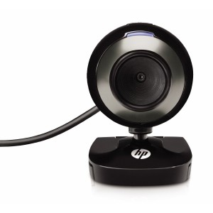
webcamThe other day, I was walking around in Fry’s Electronics, and noticed that they had HP HD-2200 webcams on sale for a mere $6. I thought to myself: hey, even if the camera is crappy (and it is) that is simply too cheap to pass up, and grabbed one. Last night, I decided to try to pair it with my Raspberry Pi and the WiPi dongle, and see if I could make a simple webcam that I could move around. Over the next 30 minutes or so, this is what I came up with.

The driver for the webcam already existed. The USB driver lists the maximum power from this webcam at 200ma, which seemed modest enough, so I configured my Raspberry Pi with the WiPi and webcam plugged in directly, without any powered hub. Technically, the combination of the WiPi and the Pi might be over the reasonable limit, but I have seen others do a similar setup, so I decided to step boldly. This is nice, because it means that you just have one plug, and the resulting package is quite compact and mobile.

Experimentation using ffmpeg to read from the v4l2 device showed that the camera needed to capture a few frames before the automatic exposure would yield a decent image, so I grumbled a bit and experimented. After 10 minutes of inconsistent results, I recalled hearing about a different but simple webcam server program called fswebcam. It’s a simple little program, and was in the package repository, so a simple “sudo apt-get install fswebcam” and I had the software installed. It’s got a pretty good man page too. Fswebcam doesn’t stream video, but it can do one-shot and periodic captures, and has a lot of the essential features that I wanted, including capturing and skipping a bunch of frames, and capturing and averaging a bunch of frames for output.

This morning, I left my camera aimed at the bed in our guest room, which is where my cat Scrappy likes to take his naps. I hoped that later in the day, I’d be able to get a picture of him. The room has some direct sun during the day, which makes for some harsh lighting, which makes the picture pretty unimpressive.

output

Nope, he wasn’t napping there. Or was he? I loaded the image into gimp, and stretched the contrast with the Levels adjustment:

scrappy

Ahah! Hiding next to the wall! (That’s a cloud painted on the wall above and to the right of him).

Pretty neat.

Oh, incidently, I didn’t have an http server installed on the Pi, but then remembered that it does have python. If you run “python -m SimpleHTTPServer” it will create a webserver that can serve files out of the current directory on port 8000.

Later, I may try to use ffserver or motion to do something fancier, but I’m happy with this setup so far.

The Raspberry Pi, and the WiPi USB dongle, with questions about power…

February 6, 2013 | My Projects, Raspberry Pi, Robotics | By: Mark VandeWettering

I’m having lots of fun with my Raspberry Pi, and I’ve decided to launch one of my crazy spare-time projects: inspired by this article detailing the construction of RUDEBOT, a kind of mobile tablet robot, I decided to build a robot of my own. But, anything worth doing is worth changing and adapting, so I thought I’d put my own spin on it, and use the Raspberry Pi and an Arduino combined to provide the brains of this robot.

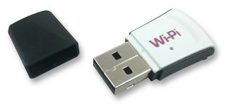
wipi The original incarnation of the RUDEBOT used an Arduino and a WiFi shield. I didn’t like this approach because the WiFi shield is, by all accounts, fairly buggy and limited, and the actual cost of the shield is rather high. It dawned on me that I could buy a Raspberry Pi and a WiPi (the tiny USB 802.11n dongle you see on the right) for less money, and I’d have the advantage of also carrying a full Linux computer on board. I could turn my incarnation into a kind of mobile hotspot, which seemed like it might be a fun thing to try. I would still use the Arduino to handle the basic motor controls with commands sent over a serial port from the Raspberry Pi. Having that much hardware on board makes all sorts of software possible.

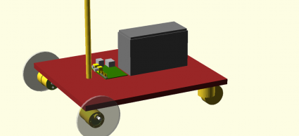
robotWhile waiting for parts to arrive, I just sort of began doodling using OpenSCAD to design the basic layout. I built CAD models for the motors and the platform, and selected a 12V 7 amp hour SLA battery. And then… began to think about power.

The documentation says that the Raspberry Pi can consume up to 700ma of current while running. Often, you’ll see that whenever anyone adds any significant USB peripherals to a Pi, they use a powered USB hub. In theory USB devices are supposed to be able to request 500ma of current from the host, but the Raspberry Pi (the second version, the originals ones had even lower power capabilities) has fuses which limit total current at 1A. So clearly, power hungry peripherals can require additional power, and a powered hub is the common solution.

But which peripherals are power hungry? In particular, it would be great if I could hook up the WiPi wireless dongle without having to provide additional power. So, I set out to research whether it was feasible. I saw three ways to proceed:

  1. Simply try it. If it works, then it works. Hard to argue with that, but it doesn’t tell you a lot about what the limits are. Would adding an additional keyboard/bluetooth/mouse push it over the edge? Undisciplined trial and error doesn’t seem like a good approach.
  2. Try it, but measure the current required. This seems like a better approach, and gives you hard data. Basically I’d need to tap a microusb cable so that I could put in my trusty multimeter, and I could measure the current directly. I probably will do that soon.
  3. Try to research how much current these things are spec’ed to use.

The last is easy to do when you have an iPad in front of you during lunch, so that’s of course what I did. But the figure that I’m interested in (power consumption) is not very often listed for USB peripherals. But it turns out that USB peripherals are supposed to give some hints to the host about how much power they require. If you plug in a peripheral to your Linux box (including the pi), you can simply use the command “lsusb -v” to get a dump of all the USB devices, and see what the driver for the hardware thinks it needs.

So, I did just that. I plugged my WiPi into the powered hub, and had a peek. Here’s the dump, most of which is pretty uninteresting, but which contains the Max Power…

Bus 001 Device 008: ID 148f:5370 Ralink Technology, Corp. RT5370 Wireless Adapter
Device Descriptor:
  bLength                18
  bDescriptorType         1
  bcdUSB               2.00
  bDeviceClass            0 (Defined at Interface level)
  bDeviceSubClass         0
  bDeviceProtocol         0
  bMaxPacketSize0        64
  idVendor           0x148f Ralink Technology, Corp.
  idProduct          0x5370 RT5370 Wireless Adapter
  bcdDevice            1.01
  iManufacturer           1 Ralink
  iProduct                2 802.11 n WLAN
  iSerial                 3 1.0
  bNumConfigurations      1
  Configuration Descriptor:
    bLength                 9
    bDescriptorType         2
    wTotalLength           67
    bNumInterfaces          1
    bConfigurationValue     1
    iConfiguration          0
    bmAttributes         0x80
      (Bus Powered)
    MaxPower              450mA

450ma. Ouch. That seems like a lot. I find it kind of hard to believe that such a tiny transmitter can pull that much current without melting itself (it’s tiny). So, I’m left with some questions:

  1. Can the WiPi really pull that much current?
  2. Can I use it without plugging it into a powered hub? Some people do seem to be doing that, and have even said that it doesn’t work properly when plugged into some powered hubs.
  3. I’m also interested in hooking an Arduino to the Pi. How much current can the Arduino pull?
  4. Ultimately, I probably will want to power all of this equipment with my 12V SLA battery. What’s a reasonable solution to powering the Pi, Arudino and potentially a powered hub? I’m looking for quick and dirty, but also reasonable and reliable.

Any hints from robot/power/Raspberry Pi experts are welcome, here or via twitter @brainwagon.

More OpenSCAD tinkering…

February 3, 2013 | My Projects, Robotics | By: Mark VandeWettering

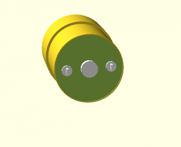
The other day, I was at Harbor Freight, and picked up an inexpensive set of digital calipers. While goofing around, I decided to try to reproduce an object using OpenSCAD. I had just received a pair of motors from Pololu. They look like this:

pololu

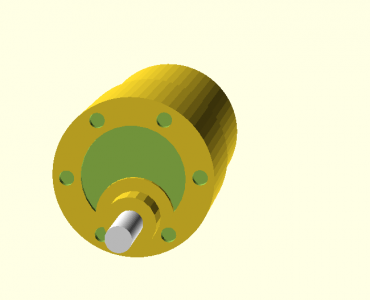
I sat in the editor, and set to work measuring. I didn’t really plan this out, I just hacked until the CSG operations worked out. I did not model the flat on the drive shaft, and only modeled the six mounting holes, not the three that hold the motor together on the front. But overall, in about half an hour, I learned a bunch and came up with the following model.

motor1

motor2

I’ll probably model the flats, and then figure out how to instantiate two of these and model a robots platform I’m imagining. More later.

Tinkering with OpenSCAD…

February 2, 2013 | My Projects | By: Mark VandeWettering

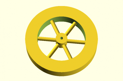
It seems like I might have access to a 3D printer, so I thought it might be fun to see what I could design. I thought using OpenSCAD, a scripting based 3D modelling software that can generate models in STL, a fairly simple but flexible format that can be printed by lots of printers. I had never used it before, but I am fairly comfortable with the ideas, so I thought I’d try a simple project: designing a 6″ (150mm diameter) wheel for a robotics project that I’m working on. It’s not really meant to be serious for construction (it is solid and uses way too much material) but it was a modest first attempt. Here’s the program I came up with in 20-30 minutes.

module dumbwheel() {
	difference() {
		union() {
			difference () {
				cylinder(h=25, r=75, center=true, $fn=200) ;
				cylinder(h=35, r=50, center=true, $fn=96) ;
			}
			rotate(a=90, v=[1, 0, 0]) {
				for (r = [0, 60, 120, 180, 240, 300]) {
					rotate (a=r, v=[0, 1, 0]) { cylinder(h=60, r=4, $fn=16) ; }
				}
			}
			cylinder(h=25, r=12, center=true, $fn=100) ;
		}
		cylinder(h=35, r=3, center=true, $fn=100) ;
	}
}

dumbwheel() ;

And it generated the following wheel.

simplewheel

I’ll have to think about this a bit more to generate a pragmatic wheel, but it’s not a bad start.

My weekend…

January 28, 2013 | Amateur Radio | By: Mark VandeWettering

I lost 1.8 pounds this week.

I went on 2 mile walk with Carmen.

I soldered some clip leads onto pennies to make a touch sensor for the Arduino.

I figured out how to run the card deck on the Computer History Museum’s 1401 restoration page that computes pi on the 1401 simulator.

                                               000000003. * 10E-00000
  1415926535 8979323846 2643383279 5028841971 6939937510. * 10E-00050
  5820974944 5923078164 0628620899 8628034825 3421170679. * 10E-00100
  8214808651 3282306647 0938446095 5058223172 5359408128. * 10E-00150
  4811174502 8410270193 8521105559 6446229489 5493038196. * 10E-00200
  4428810975 6659334461 2847564823 3786783165 2712019091. * 10E-00250
  4564856692 3460348610 4543266482 1339360726 0249141273. * 10E-00300
  7245870066 0631558817 4881520920 9628292540 9171536436. * 10E-00350
  7892590360 0113305305 4882046652 1384146951 9415116094. * 10E-00400
  3305727036 5759591953 0921861173 8193261179 3105118548. * 10E-00450
  0744623799 6274956735 1885752724 8912279381 8301194912. * 10E-00500

We saw Life of Pi in 3D. Excellent.

I played too much minecraft.

I didn’t get enough sleep.

Resources on the IBM 1401

January 23, 2013 | Retrocomputing | By: Mark VandeWettering

Okay, I was trying to find more information about the IBM 1401, and the bitsavers website again came to the rescue. If you surf over to to their directory of IBM 1401 information, you can find some nifty references. One of the most useful references is 1962 manual Programming the IBM 1401. A somewhat less conversational but perhaps more complete reference is A Guide to 1401 Programming. Another useful reference is this 1401 Data Processing System Reference Card. Armed with this information, can it be long before I write my first 1401 program?

Well, it might be, but who knows?

An IBM 1403 font…

January 23, 2013 | Computer Science, Fonts, Retrocomputing, Typography | By: Mark VandeWettering

A few days ago, I was playing around with my Raspberry Pi, trying to get a new, freshly compiled version of the TOPS-10 7.03 monitor running. I was having some difficulty with it, as it appears that a bug had crept into the code that simulates the DZ11 serial ports as telnet connections, and I could no longer login from “remote” terminals. While I was grumbling about that patiently awaiting a fix to appear on the simh github server, I started thinking about other computers. (Long time readers may remember that I suffer from occasional bits of technological nostalgia, having previously written an emulator for the PDP-1 so I could play SpaceWar! and written all sorts of fun code for the Atari 2600.)

So, I started looking into the IBM 1401.

Recently, the Computer History Museum completed a restoration project to bring an IBM 1401 back from the dead. Actually, they have now have two. Each weighs about 4 tons, and the 1401 was quite possibly the most plentiful computer back in 1964 when I was born.

It’s a really odd machine. You can read more about it here. It was mostly implemented using diode-transistor logic (now you know where my recent poking at DTL logic came from). It had core memory, with up to 16Kbytes! The first machines where announced in 1959, and construction ceased in 1971 as the IBM/360 architectures became dominant.

But all this is really an aside. I was thinking about my DEC experience, and started thinking about the line printers we had back then. Unlike the quiet woosh of today’s laser printers, these where heavy, loud, mechanical monstrosities, but they were fast. They could spew out a printed sheet of green bar paper in about six seconds, and if you had lots of form feeds, could eject 75 inches of paper each second. I remember seeing someone do that at the University of Oregon (probably on a DEC LP20) and you could visibly see the stack of fanfold beneath the printer drain away).

I suspect that the printer hooked to our DEC-1091 at the University of Oregon in the early 1980’s might have been an LP20, but I got hooked on researching the technology with some judicious googling, and found references to the IBM 1403 printer, which was commonly paired with the IBM 1401. I ran across this page about the IBM 1401 restoration, which included the following example print sample:

1403Font-

I liked it. So, on Twitter, I idly mentioned that I wondered if anyone had created an IBM 1403 inspired font.

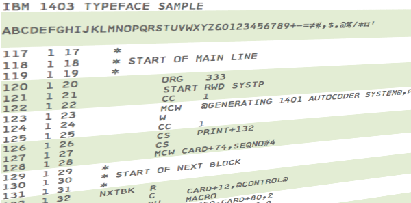
And it turned out that a hacker friend of mine with diverse interests, Jeff Kellem (@composerjk) heard my call. Among his interests and talents is typography and font design. Jeff took some print samples and started working on a 1403 inspired font. While he’s not ready to release yet, the preliminary results look awesome:

sample-text-listing2-12pt-clip-perspective-small

What is even cooler is that Jeff wrote up some notes on his blog about how he did it, as well as some additional inspiring links about the 1401 restoration project. Great stuff, and thanks to Jeff!