Okay, a few weeks ago I bought a little Dewalt DW745 table saw for use in my garage. I’ve never actually owned a table saw, but lately I’ve been wanting to do more construction, and I thought investing a fairly small amount of money in a table saw would be a good way to go.
And I’ve begun to do experiment with some cheap, simple projects to learn how to operate it and operate it safely.
The way I’ve decided to start is by trying to research and build some simple jigs to help me safely and accurately cut pieces of various types. One of the jigs which everyone recommends that you build is a cross cut sled.
I had some old 3/4″ plywood lying around my shop, left over from when I built my last telescope more than a decade ago. I decided to rip some pieces to form the bed and the two ends of the cross cut sled. It was good practice. All the pieces had nice clean edges, and sighting along them and checking them with a square shows the edges to be nice and straight.
The only part that I didn’t have was material to make the rails that will fit in the miter slots. While I have a fair amount of scrap plywood and softwood like Douglas Fir 2x4s lying around, I haven’t done any hardwood woodworking before, so I don’t have the usual oak or maple that most people use for it. I will probably go out and source some 1″ material I could trim down over the next few days, but while thinking about it, I ran across this nice video series of videos to help newbies like myself build their first cross cut sled.
They suggested that it actually is reasonable to cut runners out of plywood, at least if you use a good quality plywood like Baltic Birch. As it happens, I don’t have any of that either, but there is still a lot of good information here which I’m trying to absorb. If you are a beginning woodworker, you could probably learn some good stuff from this series too.
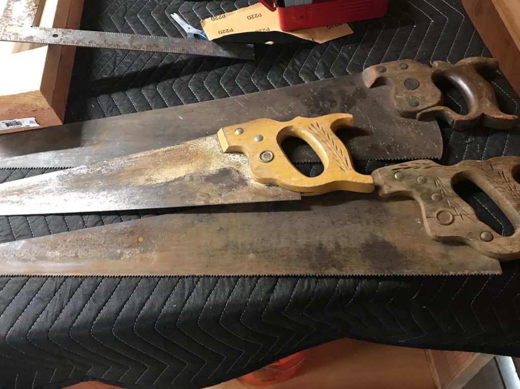
I heard some friends of mine that I haven’t seen in some time were having an estate sale, so I drove over to say hi and, well, to also see if they had anything interesting. Lately I’ve become interested in doing more work in my shop, and I’ve always had a bit of a fondness for old tools, even though I know almost nothing about them. I had a nice visit, and then dug around. In their old workshop, I found I found this trio of old saws, which they generously donated to me. They are a bit dirty and rusty, and I don’t know anything about old tools really, but I liked the shape of the handles and the wheat motif that was carved into the handles, and imagined that they were probably fairly old.
In fact, I think they are probably over a hundred years old. I took some photos, and will ponder what I’m going to do with them. At the very least they could stand a bit of rust removal and cleaning, and probably have some linseed oil rubbed into the handles.
As you can see, these are a little rusty and dirty, but it’s mostly surface corrosion, and they are in pretty good condition. I doubt you would really call them sharp, but they are not missing any teeth, and they are straight and even. One has a fairly loose handle, and the one pictured on the bottom has a split in the handle. The handles are secured to the saws with screws which are (I believe) brass.
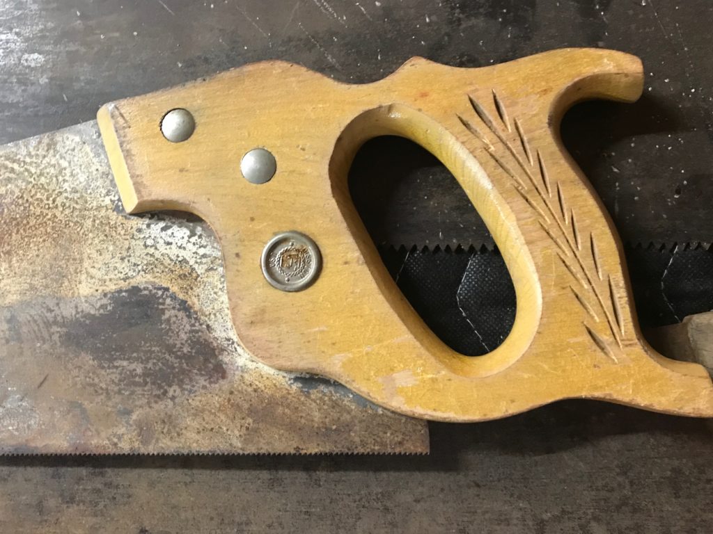
This one is probably in the roughest shape. As you can see, the wood is split right through the medallion in the center, and there is a fair amount of sticky, gloppy looking stuff stuck onto the handle, specially near the base of the wheat motif.
Here is a not very good picture of the medallion. It’s fairly corroded, but I haven’t tried to clean it yet. My guess is that it says “DISSTON”, but I’m not 100% sure. I looked at this quick identifying chart, and believe it to be a Disston D-23 or one of the related models. Neat!
The next saw:
has another dirty/gunky medallion.
It is pretty clearly another Disston saw, also tagged with USA. I think it might be a No. 76, but I’m not sure. If so, it’s a bit more rare than the first saw, and while the blade is in kind of gunky condition, the handle and hardware appear much better. Overall the feeling of the saw is more modern, but what do I know?
The last is a different manufacturer.
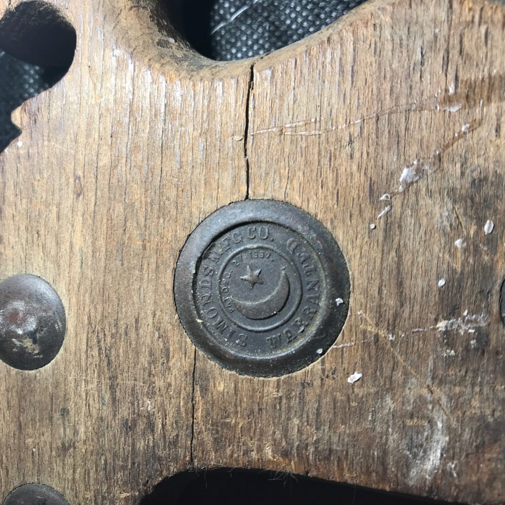
Rather odd construction to my eyes. The slotted/split construction is particularly odd, and the curves are more exaggerated. Looking at the medallion:
Reveals a kind of nice motif with a crescent moon and five pointed star, and “SIMONDS MFG CO. WARRANTED”. I wasn’t able to find too much more information about this in a casual Google, but it’s a cool medallion.
Anyway, I doubt I am going to be using them for much woodworking, but I thought they were cool objects. I’ll probably try to get them cleaned up at least, remove the rust and figure out some way to display them. If anyone has more knowledge/expertise about old handsaws you can email me or drop a comment. I’d love to know more.
A couple of days ago, I found out about thecavepearlproject.org through a link on hackaday, and an article which gave an interesting idea about how to do temperature sensing using an Arduino and no additional parts. I didn’t really recap the actual underlying technique. The idea was a fairly interesting one. The watch dog timer (WDT) in the ATmega328 (the chip of many Arduino variants) is normally used to help detect if your embedded application has crashed or hung. You configure the watchdog timer to trigger a routine (ISR, or Interrupt Service Routine) after a given interval, say one second. In your application’s main loop, every once in a while you “feed” the timer by calling the wdt_reset function. This resets the timer, and keeps the ISR from triggering. If your application goes into a loop or hangs, then the wdt_reset won’t get called, and when the timer expires, it triggers the routine (perhaps resetting system).
What does this have to do with temperature sensing? The WDT is driven by an oscillator inside the ATmega328, and which runs independently of the main (usually crystal) oscillator. And, as it happens, it is not engineered to be especially accurate or stable. It is not derived from the input crystal (crystal oscillators are normally pretty stable). In particular, it is not designed to be temperature stable. And it’s not. It’s that instability that makes using it for temperature sensing. You measure the time it takes to trigger the WDT, and then, with a little math (more below) you can figure out the temperature.
Anyway, that’s the theory. I wanted to give it a whirl. So, I tinkered together some code, using my favorite development environment platformio, and running on a Sparkfun RedBoard, with some other sensors that I had lying around: an Si7021 temperature humidity sensor and a DS3231 real time clock. Previous data logging experiments I had done mostly used to log data to the Internet (I mostly have been using ESP8266 boards like the WeMOS D1 Mini), but I was inspired by the work on The Cave Pearl Project website, so I decided to try to log the data to a MicroSD card instead. So, I tinkered this code together:
#include <SPI.h>
#include <Wire.h>
#include <SdFat.h>
#include <RTClib.h>

#include <avr/sleep.h>
#include <avr/wdt.h>

/*  _
 * | |__ _  _ _ _ _  _ __ _ _ _
 * | '_ \ || | ' \ || / _` | ' \
 * |_.__/\_,_|_||_\_, \__,_|_||_|
 *                |__/
 * an Arduino based data logger
 *
 */

#define BUNYAN_VERSION          "1.00"

////////////////////////////////////////////////////////////////////////
RTC_DS3231 rtc ;
////////////////////////////////////////////////////////////////////////

void
fault()
{
    Serial.println("::: SYSTEM FAULT RECORDED") ;
    delay(10) ;
    for (;;) ;
}

////////////////////////////////////////////////////////////////////////

////////////////////////////////////////////////////////////////////////
// microSD card adapter settings
////////////////////////////////////////////////////////////////////////

SdFat SD ;
SdFile f ;

void
motd()
{
    int ch ;

    if (! SD.exists("README.TXT")) {
        Serial.println("::: no motd") ;
        return ;
    }

    if (f.open("README.TXT", O_RDONLY)) {
        while ((ch=f.read()) > 0) {
            if (ch == '\n')
                Serial.write('\r') ;
            Serial.write(ch) ;
        }
        f.close() ;
    } else {
        Serial.println("motd: not found.") ;
        fault() ;
    }
}

////////////////////////////////////////////////////////////////////////
// It's useful to be able to detect all the devices on the I2C bus.
////////////////////////////////////////////////////////////////////////

int
i2cprobe(int addr)
{
    byte error ;
    Wire.beginTransmission(addr) ;
    error = Wire.endTransmission() ;
    return error == 0 ;
}

void
i2cdetect()
{
    char buf[12] ;

    Serial.println("    SCANNING ALL I2C ADDRESSES") ;
    Serial.println("    =======================") ;
    for (int i=0x08; i<0x78; i+=8) {
        Serial.print("    ") ;
        for (int j=0; j<8; j++) {
            if (i2cprobe(i+j))
                snprintf(buf, sizeof(buf), "%02X ", i+j) ;
            else
                snprintf(buf, sizeof(buf), "-- ") ;
            Serial.write(buf) ;
        }
        Serial.println() ;
    }
    Serial.println("    =======================") ;
}

////////////////////////////////////////////////////////////////////////

volatile boolean WDTalarm=false;

ISR(WDT_vect)
{
    wdt_disable() ;             // only fire once.
    WDTalarm=true ;
}

////////////////////////////////////////////////////////////////////////

#include "Adafruit_Si7021.h"
Adafruit_Si7021 sensor = Adafruit_Si7021();
////////////////////////////////////////////////////////////////////////

char msgbuf[40] ;

char fname[40] ;

void
setup()
{
    // Most of the time, we won't really have (or need) a serial
    // cable attached to the data logger, but during development it
    // is convenient, and I'm not really working at trying to eke out
    // every last bit of battery life, so we'll go ahead and turn it on
    // here.

    Serial.begin(115200) ;


    // wait for the serial port to be initialized
    while (!Serial) delay(10) ;

    Serial.println("BUNYAN Version " BUNYAN_VERSION) ;

    Wire.begin() ;
    i2cdetect() ;
    Serial.println() ;

#if 1
    Serial.println("::: testing WDT_count()") ;
    snprintf(msgbuf, sizeof(msgbuf), "::: CNT=%ld", WDT_count()) ;
    Serial.println(msgbuf) ;
#endif

    // I envision A0 to be connected to a simple resistor divider, so we
    // can keep track of the battery voltage.

    Serial.println("::: A0 set for analog input") ;
    pinMode(A0, INPUT) ;

    // Try to setup the SD card...
    snprintf(msgbuf, sizeof(msgbuf), "::: SPI MISO=%d MOSI=%d SCK=%d CS=%d",
        MISO, MOSI, SCK, SS) ;
    Serial.println(msgbuf) ;

    if (!SD.begin(SS, SD_SCK_MHZ(4))) {
        Serial.println("::: unable to initialize microSD card reader") ;
    }

    motd() ;

    if (i2cprobe(0x68)) {
        Serial.println("::: found DS3231 at I2C address 0x68");
        rtc.begin() ;
        if (rtc.lostPower()) {
            Serial.println("::: DS3231 lost power, resetting time.") ;
            rtc.adjust(DateTime(F(__DATE__), F(__TIME__)));
        }
        DateTime now = rtc.now() ;

        snprintf(msgbuf, sizeof(msgbuf),
                "::: %02d/%02d/%04d %02d:%02d:%02d [%ld]",
                now.month(), now.day(), now.year(),
                now.hour(), now.minute(), now.second(),
                now.unixtime());
        Serial.println(msgbuf) ;

    } else {
        Serial.println("::: could not find DS321 RTC module") ;
        fault() ;
    }

    if (sensor.begin()) {
        Serial.print(F("::: found "));

        switch(sensor.getModel()) {
        case SI_Engineering_Samples:
            Serial.print(F("SI engineering samples")); break;
        case SI_7013:
            Serial.print(F("Si7013")); break;
        case SI_7020:
            Serial.print(F("Si7020")); break;
        case SI_7021:
            Serial.print(F("Si7021")); break;
        case SI_UNKNOWN:
        default:
            Serial.print(F("Unknown"));
        }

        Serial.print(" Rev(");
        Serial.print(sensor.getRevision());
        Serial.print(")");

        Serial.print(" Serial #");
        Serial.print(sensor.sernum_a, HEX);
        Serial.println(sensor.sernum_b, HEX);

        float fT = sensor.readTemperature() ;
        float fH = sensor.readHumidity() ;

        int iT = (int) (100. * fT) ;
        int iH = (int) (100. * fH) ;

        snprintf(msgbuf, sizeof(msgbuf),
                "::: TEMP=%d.%02d RH=%d.%02d%%",
                iT / 100, iT % 100, iH / 100, iH % 100) ;

        Serial.println(msgbuf) ;
    } else {
        Serial.println("::: could not find temperature humidity sensor") ;
        fault() ;
    }

    int cnt = 0 ;

    do {
        snprintf(fname, sizeof(fname), "DATA%03d.CSV", cnt++) ;
    } while (SD.exists(fname)) ;

    Serial.print("::: Using ") ;
    Serial.print(fname) ;
    Serial.println(" for data.") ;

}

// https://thecavepearlproject.org/2019/02/25/no-parts-temperature-measurement-with-arduino-pro-mini-to-0-005c-or-better/

unsigned long
WDT_count()
{
    noInterrupts() ;
    MCUSR = 0 ;
    WDTCSR |= (1<<WDCE) | (1<<WDE) ;                    // prep for update
    WDTCSR = (1<<WDIE) | (1<<WDP2) | (1<<WDP1) ;        // and change it to 1s
    wdt_reset() ;
    WDTalarm = false ;
    interrupts() ;


    unsigned long st = micros() ;

    while (!WDTalarm) {
        set_sleep_mode(SLEEP_MODE_IDLE) ;
        noInterrupts() ;
        sleep_enable() ;
        interrupts() ;
        sleep_cpu() ;
        sleep_disable() ;
    }

    return micros() - st ;
}

void
loop()
{
    Serial.print("::: LOGGING TO ") ;
    Serial.println(fname) ;

    if (f.open(fname, O_CREAT | O_APPEND | O_WRONLY)) {
        Serial.print("::: ") ;
        Serial.print(fname) ;
        Serial.println(" open, logging data") ;

        // First, get the time
        DateTime now = rtc.now() ;
        snprintf(msgbuf, sizeof(msgbuf),
                "%ld,", now.unixtime()) ;
        f.print(msgbuf) ; Serial.print(msgbuf) ;

        // and the temperature and humidity
        float fT = sensor.readTemperature() ;
        float fH = sensor.readHumidity() ;
        int iT = (int) (100. * fT) ;
        int iH = (int) (100. * fH) ;
        snprintf(msgbuf, sizeof(msgbuf),
                "%d.%02d,%d.%02d,",
                iT / 100, iT % 100, iH / 100, iH % 100) ;
        f.print(msgbuf) ;
        Serial.print(msgbuf) ;


        unsigned long wd_cnt = WDT_count() ;
        snprintf(msgbuf, sizeof(msgbuf), "%ld,", wd_cnt) ;
        f.print(msgbuf) ;
        Serial.print(msgbuf) ;

        f.println() ;
        Serial.println() ;

        f.close() ;
    } else {
        Serial.println("::: Problem saving data.") ;
    }

    // Wait for a minute, then begin again...
    delay(5000) ;
}
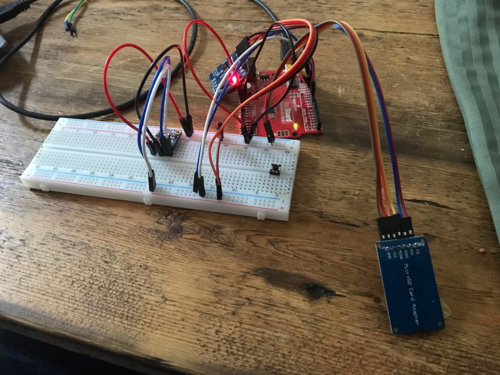
And I wired up the hardware on a breadboard.
Yes, it is just a mess, just like the code.
The data file looks like this. Each line consisted of a time stamp , the temperature and humidity reported by the Si7021, and then the time (in microseconds) that it took the watchdog timer to overflow.
I left this running on my dining room table overnight, recording the data every five seconds (overkill, but why not?) and in the morning I had a data file with about 7800 entries. So, the question was, what to do now? How could I figure out how to convert the raw counts into temperatures?
The answer is of course “math” and the tool I like to use when doing math with computers (particular when the math consists of lots of data) is the numpy library. It turned out that the numpy.polyfit function is just what we need. I wrote 17 lines of code (only two or three which are interesting) to compute an order 2 polynomial that will convert the counts into temperature. I also computed RMS error, and found that the RMS error for the fit curve was about .128 degrees. Not bad at all, and probably pretty comparable to the Si7021.
!/usr/bin/env python
 import numpy as np
 a = np.loadtxt("data008.dat")
 cnt = a[:,3] - 1e6
 temp = a[:,1]
 p = np.polyfit(cnt, temp, 2)
 ptemp = p[2] + cnt * (p[1] + cnt * p[0])
 e = ptemp-temp
 print "# rms error %.3f" % np.sqrt(np.sum(e * e) / len(e))
 for a, b in zip(ptemp, temp):
         print "%.2f" % a, b
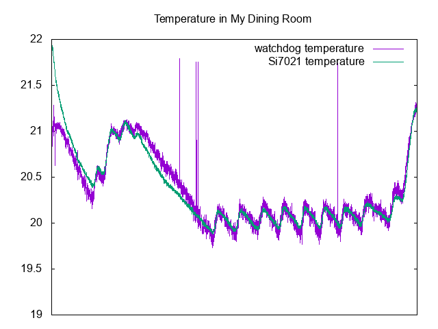
Here is a graph comparing the two (plotted with gnuplot):
As you can can see, there is a bit of deviation at the very beginning (perhaps caused because the board itself had not been powered before, and therefore may not be subject to self-heating), and there are a couple of glitches, but overall the predicted value is a bit noisier, but tracks the temperature from the “real” sensor pretty well.
What’s left is to try to calibrate the sensor over a much larger temperature range, and to potentially determine how to compensate changing battery voltage if I were to power it from an unregulated source. But it seems like a completely viable way to do temperature sensing, at least if you take the time to calibrate the temperature against a known source (the same coefficients will not carry over between individual boards).
Addendum: The code above was pretty simple, but I did encounter one issue. I had been slowly adding functionality to the sketch, when suddenly code that had worked before began acting erratically, resetting the board and generally causing chaos. I spent about 20 minutes scratching my head, then went away and came back to it later. I then realized that what probably was happening was that I was nearing (or exceeding) the amount of RAM memory for the sketch. I hadn’t been using the ATmega328 in a while, and had forgotten that it only has 2K, so that’s actually pretty easy to do. In addition, the SdFat library consumes a fair amount of RAM as well, so you have to be careful. I did a few things to trim back memory consumption, and should go back and make sure that all the constant strings that I use for information printout are wrapped in the F() macro to make sure that they are stored in flash. If you do not do that, then they get copied into RAM, which is no good at all for memory consumption, and almost certainly not needed.
I’m still heading toward changing my Creality CR-10 over to use a BLTouch bed leveling sensor, but I still need a few parts that I’m waiting on. I thought it might be a good time to try some prints with a filament that I never used before: namely a roll of Sainsmart TPU filament that I bought months ago but was too chicken to try.
TPU is a soft and stretchy filament which presents some challenges, especially for prints like the CR-10 which uses a Bowden extruder. The filament is pretty soft and compressible, which means that the extruder has to work very slowly to keep the pressure down sufficiently to keep it from bunching up and jamming in the printer. Most people also recommend modifications to the extruder to make sure that the filament enters the feed time immediately after exiting the feed gear. Otherwise a common failure mode is for the pressure to build up and for the filament to kink right there, causing extrusion to stop. My new aluminum replacement extruder hardware seemed pretty good from this perspective, so I thought I’d give it a shot.
Calibration cats, in PLA at 100% and 50% scale
I used most of the suggested settings from the Sainsmart page, which basically meant slowing down the print speed to between 15mm and 30mm/s, and go even slower on the first layer and to disable retraction. For my first test print, I decided to use a calibration cat that I often use for test prints, and is slightly less boring and not much more difficult than a simple cube.
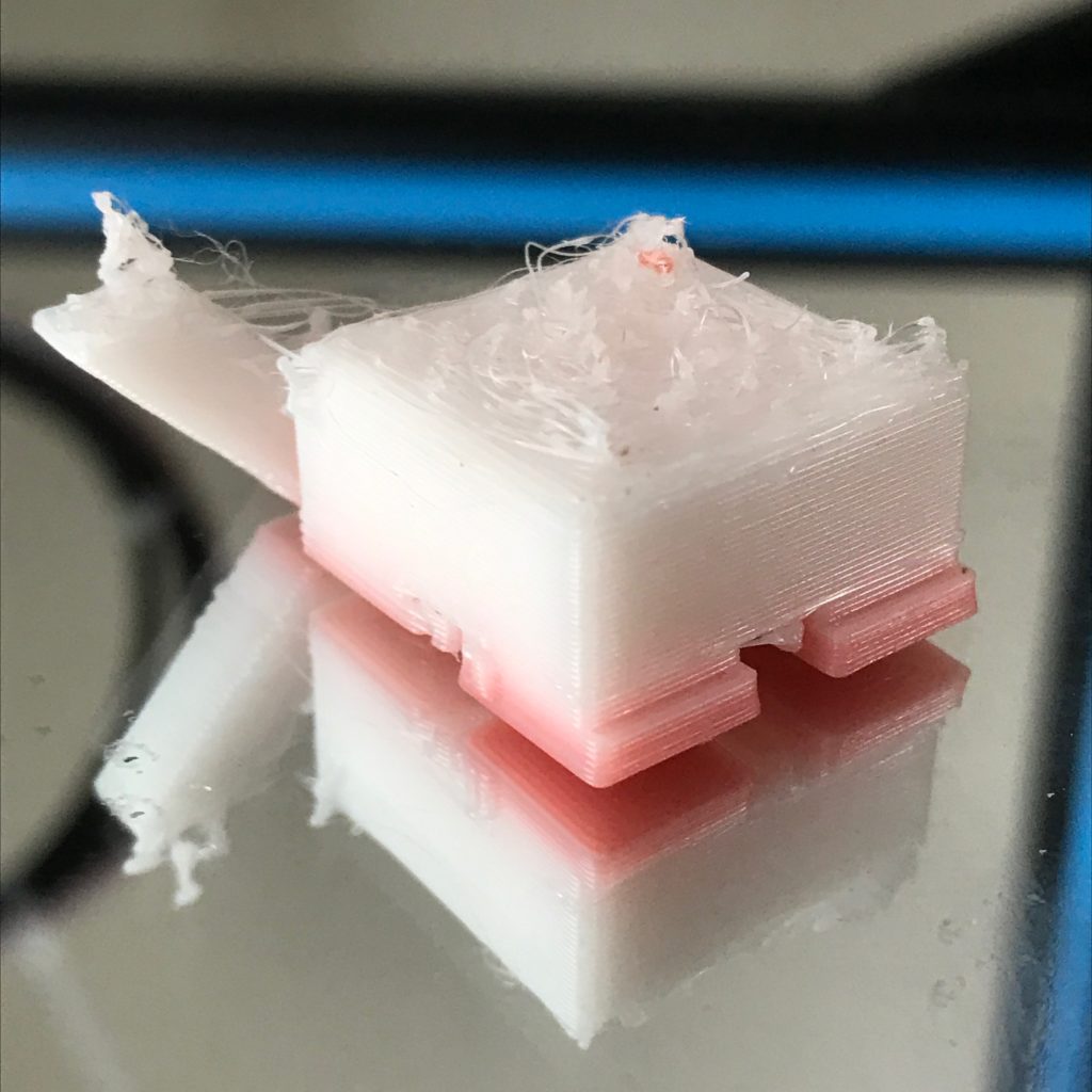
Failed attempt at Sainsmart TPU. Pink is from leftover red PLA in the extruder.
Sadly, it didn’t go particularly well. I had two failures in a row which were basically caused not such much by filament backing up in the tube, but by some back pressure causing the drive gear to stop getting traction on filament, and it just ceases to advance. This happened about 1cm into my first print, so I decided to up the temperature a bit to hopefully reduce the pressure and try again. That print failed almost immediately, about three layers in.
This caused me to abort my attempt for the day, and go off and scratch my head some more.
The obvious things to try would seem to be:
Additional temperature changes (higher, perhaps as high as 230?) but I think that higher temperatures also increase stringing and other undesirable problems.
Make sure that my drive gears are sharp and see if I can increase the tension on the drive spring.
Go even slower. Perhaps 15mm/s or even 10mm/s is reasonable.
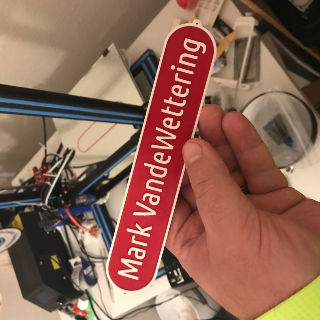
A name plate, printed in two different colors of PLA filament on my Creality CR-10.
Over the last couple days, I’ve been pondering my journey through 3D printing. After having taken a three month break from it (more on that below) I’ve managed to get my Creality CR-10 back up and running in a reasonable way, and have donated my Anet A8 (my gateway drug to the world of 3D printing) to our hacker space at work, and I’m slowly tinkering it back into fighting shape. Last night I decided to try the “change filament” option in the Marlin firmware for first time, and it worked really well. I made the name plate pictured on the right, first by laying down the base in Fire Engine Red PLA I had, and then once the layers with the embossed lettering started, initiating a Filament Change from the front panel. This stopped the print in progress, moved the hot end off to the side and then retracted the existing filament and told me to load the new color. I used 3D Solutech white. The firmware allows you run several purge cycles to get the old color out. It took several tries to get the filament to turn reasonably white, as opposed to pink, but then I hit continue and it worked perfectly. Neat, and with no fancy G-code modifications.
And this has got me thinking about writing up what I think is good and bad about my choice of 3D printer, and where I think the perfect “hacker” 3D printer might be going.
My first printer was an Anet A8. They are still available, and very inexpensive, at $150. I do not recommend them as a printer, even though I had a lot of fun with mine. It’s actually a remarkably capable little printer, and I made some pretty impressive prints with mine. The pluses?
It’s inexpensive, at just $150 or so.
It is (or at least was) a fairly popular option, so a large community with lots of information and upgrades is available.
Replacement parts are cheap.
It runs the Marlin open source firmware, so upgrades are relatively easy to perform.
But it does have a number of significant drawbacks.
It’s not just inexpensive: it’s cheap. The frame is from laser cut plastic, and it’s easy to break parts if you overtighten bolts. In fact everything about the printer is cheap. I spent a lot of time replacing parts which are broken or just substandard.
It’s not ready to go out of the box. It comes as a kit, and there is a lot of assembly. It took me the better part of a weekend to get it going properly.
It is not very well engineered for safety. By default, the version of Marlin installed on mine didn’t even have overheat cutoffs. The connectors used to power the hot bed are not really sufficient to handle the current, and present a fire risk. I wouldn’t leave the Anet printing unattended without a serious audit of all the safety features.
I hate the bed leveling. This isn’t unique to the Anet, I hate it period, but the Anet is pretty bad. The hot bed on mine was not even close to flat, probably well over a millimeter down in the center. Printing directly on the hot bed (or covered with tape) seems wrong. And my pet peeve: nothing that needs to be leveled should ever do so with four screws. It’s overconstrained and never works right. When I used to make telescopes, all my mirrors were adjusted with three screws, which are all you need to define a plane.
The extruder is a direct drive MK-8 extruder. There are reasons to like the direct drive. In theory, they allow you to use less retraction and they will have less stringing than the Bowden type. But there are several pragmatic issues that make me despite them. They seem more complicated to assemble and disassemble. Because the stepper is mounted right next to the heat block, they carry more mass than a simple Bowden style. Loading and unloading filament is kind of a pain, as you don’t have any way to visually inspect the entry of the filament into the hot block. And the way that it’s mounted on the A8 is annoying, and requires that you unscrew a set screw which is awkwardly placed underneath the assembly when its mounted in the printer.
After tinkering with mine for three months, I was sufficiently excited by 3D printing to justify getting a new printer. I settled on the equally (or perhaps more) popular Creality CR-10. This has become my workhorse printer (well, since I use it primarily for tinkering, perhaps “workhorse” is the wrong word, but you get the idea…)
The Creality CR-10 has a number of significant advantages:
It is a very popular machine, with lots of information and support.
It supports the Marlin firmware as well, so upgrades are fairly common.
It’s much less of a kit. It comes in three parts, and if you know what you are doing, you can probably assemble and get the whole thing going in an hour or so. Not quite “out of the box”, but pretty close.
It has a 300mm print bed, and can handle prints up to around 400mm high. That is an awesomely large print bed.
The electronics are housed in a custom aluminum enclosure, and so has a much less erratic appearance compared to the A8.
It uses 2020 Aluminum extrusion for all the structure members.
It uses a Bowden style extruder, which makes the moving parts on the X gantry much lighter and generally easier to service. Loading and unloading filament is much easier.
It is more expensive (~$400) but generally just feels like a better engineered product. I am not constantly terrified that it will burn my house down if I turn my back on it.
I really like mine. I think that it’s an excellent buy if you are a tinkerer and want to learn a lot about the nuts and bolts of 3D printing, but don’t want to either invest a ton of money nor waste your time with a pile of substandard parts. But there are still things which I don’t like about the Creality CR-10, and I’d be remiss if I didn’t enumerate some of them.
Fans are noisy, and it has a lot of fans. The extruder carries two small fans, which are usually not a lot of trouble, and are straightforward to upgrade. The worst ones are inside the power supply/control box. And while we are complaining about the control box, it’s annoying to open to gain access, and you will need to gain access to upgrade its firmware because the controller doesn’t contain a proper Arduino boot loader.
The Anet A8 had dual Z steppers, which helped keep the X axis level. The Creality drives only one side, and to keep it level and moving smoothly, you have to adjust it fairly carefully and keep the tension just right. There are upgrades for the Creality to make it a dual Z machine, but that’s an extra cost and I haven’t done mine yet.
The extruder is a Bowden sort, which means that only the heater and fans are carried on the X-axis. That also simplifies the mechanics there, but the stock housing is pretty bulky and makes access and viewing of the nozzle more cumbersome. It also has questionable value in directing the nozzle fan. Updated “fangs” are available, I printed the Petsfang v2 for mine, which I have my own complaints about (it’s a pain to install and take off, and it’s not the easiest thing to print) but it works better.
All the bed leveling issues I had with the Anet A8 are true for the CR-10 as well. I installed an https://www.th3dstudio.com/ezabl-kit/EZ-ABL bed leveling kit on mine to help, and while it does work, it’s been a bit fussier than I would like. The overall repeatability of measurements seems pretty iffy (maybe only accurate to 0.2mm) and occasionally much worse. I think if I were to redo it, I’d probably go with a BLTouch instead.
The bed itself wasn’t super flat (probably off by half a millimeter). I covered it with a piece of mirror tile from Lowes, which helped, but I ended up using 5×5 probing to help get things to lay flat on the first layer. Honestly, can we actually get flat build plates? The telescope maker in me hates this with the power of a burning sun.
The controller is based upon the ATmega 1284, which means that the Marlin firmware fits barely into the controller. When new features come out, sometimes you have to disable other functionality to get them to work. I’ve been using the TH3D Unified Firmware Package which works pretty well, but I do wish we had more space. A replacement motherboard is actually pretty expensive to replace ($40) and doesn’t have replaceable stepper drivers, which makes a failed stepper driver a bigger issue than it should be. A motherboard like the MKS Gen L is only $20 or so and allows the possibility of replacing the driver modules with higher quality (and quieter) drive modules. I haven’t done that, but I like the idea. The overall board layout seems nicer as well, and the board supports dual extruders and has the ATmega 2560 which has double the flash space.
I’ve mostly done printing with PLA and a smattering of PETG. I tried to get the bed to heat to 100C for printing ABS, and it seemed like the maximum temperature it could reach was about 82C. If you are wanting to print ABS, you’ll probably need to do some mod to insulate and/or boost the power to the hot bed.
In the end though, I guess I mostly like the Creality CR-10 because nothing about it is very mysterious or proprietary. It is in some ways a fairly obvious design, with lots of room for tinkering, replacement or improvement. It is also capable of making good quality prints at a reasonable cost. I have been considering pickup up an Ender 3, which is the little brother to the Creality for jobs which are smaller, and maybe updating the CR-10 to use a larger nozzle (0.6mm) for larger coarser prints. I’ve also been thinking that it would be possible to easily create a home brew printer using aluminum extrusion, an MKS Gen L (or even better) mother board, and many of the same parts that I would use on the CR-10.
But for now, the CR-10 works well for me, and for the pointless kind of things I do, it’s a nice little printer.
If you have any questions or would like to add any of your experiences, leave a comment.
Okay, as per the previous installment, I carted my new current transformer tap upstairs, and plugged in the Litter Robot. It entered its startup sequence, which ran the motors back and forth, and I was able to grab some data. It looked like the following:
Just 28mV peak to peak, and looking nothing like a sine wave…
Using the built in ADC of an Arduino would give me relatively little accuracy, and the shape of the waveform isn’t super pretty. This gives me some pause.
But it was immediately apparent to me that I was amazingly stupid, and I was totally taking the wrong tactic, with the result that I was making things way too complicated.
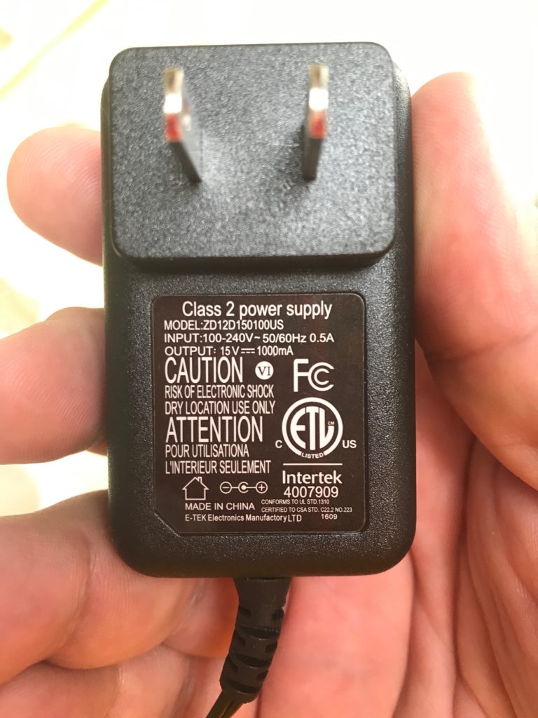
See, the fact is that the Litter Robot plugs into the wall, but it does so via this little wall wart:
Input is rated at just 0.5A, output is 15V at 1A.
It is nominally rated at 120V at 0.5A, which means that even if it was running flat out, it would generate a voltage of just 50mV. But I suspect that the reality is that the voltages will be quite a bit lower, because the Litter Robot doesn’t actually take that much power, and because the current transformer probably doesn’t operate very well at these very low current levels.
In other words, I’m using the wrong sensor for the job. I went this direction because my inspiration Brian was already going down this path and I was interested in AC sensing, but had I thought about it, the obvious way to implement what I wanted would be to put a current sensor in the output of the wall wart. In fact, I have a perfectly reasonable sensor for detecting current (and voltage) in that kind of situation: an INA219 based I2C current sensor that is identical to the ones I used in my DC current loop for my solar satellite project. These sensors actually have pretty good sensitivity down to the milliamp range, are inexpensive and compact, and I wouldn’t have to tinker around with mains voltage. It is true that I have used them mostly in DC current sensing applications, but it should not be especially difficult to use them to detect AC current. The wart puts out DC of course, which makes it doubly easy. I’ll review the datasheet and start to figure it out.
I really should think these things out first, before I order parts.
Okay, here’s a strange little project that is pushing the limits of what I understand in a couple of ways, and I thought I might write it up and also ask a question from those more knowledgeable than me.
Here’s the idea: in our upstairs bathroom, we have a Litter Robot. This is a commercial product, and basically is a spherical pod that serves as a litter box. When the cat does his business, motion detectors note his arrival and departure, and several minutes later motors engage which rotate the pod around and cause the waste to be sifted and removed from the box, and then rotates back to its starting position. Our cats seem to like it just fine, and it means that daily scooping isn’t required. Huzzah!
As it happens, there is an add-on to this model which makes it an IoT device and it will communicate its operation and control via BlueTooth to your phone. I thought this was a kind of frivolous (and not inexpensive) addition, so we didn’t bother. But refusing to spend a lot of money on a well designed product means I can spend a similar amount of money to bodge something of my own that will be a finicky Rube Goldberg. I justify this by noting that it is a learning opportunity.
I should also thank Brian who inspired this project with a similar “cat litter box” theme: he wants to automatically trigger an exhaust fan. I’m more interested in just the “sensing” part, and may use something like dweet.io or possibly MQTT to merely log when the Litter Robot does a cycle.
Rather than try to do any reverse engineering of this (rather expensive) robot that my wife really loves, the approach that I thought would be most reasonable (and which Brian is again responsible) is to create a current sensor that will note when the current to the robot increases, indicating that the motors are engaged. The way that we decided to do that is by using a current transformer. The idea is to basically create a short extension cord that passes the hot wire from the AC circuit through the center of a clamp on current transformer. You can plug this into the wall, and plug the desired appliance into the other side, and the current transformer will supply a signal (either current or voltage depending on what type you get) that can be sampled by a microcontroller, and you can then do appropriate action depending on what you discover.
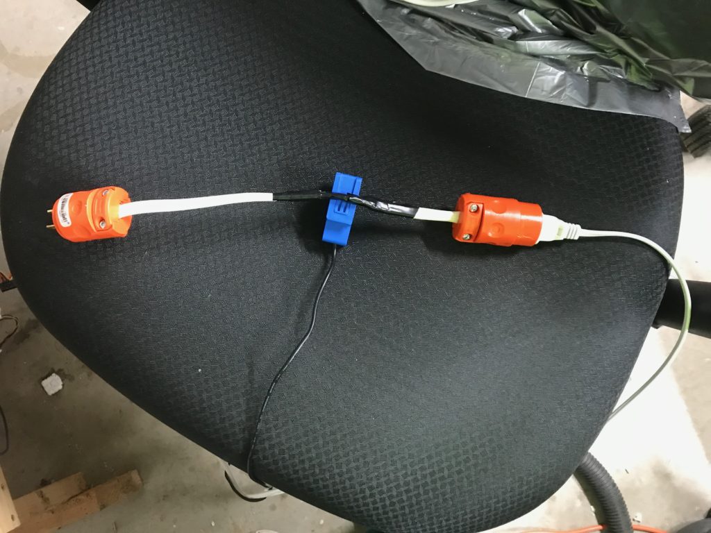
So, a scrap piece of Romex, and a trip to Home Depot later, along with an order for a current transformer, and I created this little experiment (again, following in Brian’s footsteps):
An short extension cord, with a YHDC SCT013-010 current transformer…
The extension cord is just indoor Romex, which consists of three 12 gauge wires in a plastic cover. The ground wire is basically a bare copper wire, and it has two insulated wires which are white and black. You wire the bare wire to the green plug, and then put the white on the silver screws in each end, and the black on the gold colored end. I then checked the operation, first with a wiring fault detector, and then by just trying to use it as an extension cord. No problems were noted, so it was safe to proceed.
I then slit part of the out covering to expose the inner wires. The current transformer is (I’m told) only supposed to have the “hot” or black wire passing through it, so I created a little slack and passed it through the snap on part of the current transformer. A little electrical tape (and a little more for good measure) and I was done.
The current transformer is an SCT013-010 from YHDC which cost about $15 via Amazon with Prime. Here, I will tell you pretty much all I know about such things, since I am well out of my areas of knowledge and experience (which is rather the point of this project).
A current transformer is used to monitor the current flow in a circuit. When the current flows through the hot wire which passes through the center of the ferrite core, it induces a much smaller current on the output of the secondary.
If the current transformer is of the “current output” type, then a shunt resistor (called the burden resistor) is normally placed across the output, and the voltage drop is measured across it. Since you know the voltage drop and the resistance, you can solve for the current through the secondary, and then use the specification of the transformer to compute the current through the primary circuit. Normally the output of such a transformer has a pair of protection diodes wired across the outputs because if the secondary output is an open circuit, the switching of the AC causes large voltage spikes at the output, which isn’t good.
If the current transformer is of the “voltage output” type, then the burden resistor is built in to the transformer, and the output is merely a voltage. There doesn’t appear to be a pair of protection diodes that were present in the current monitoring type, likely because the resistor is built in.
The type that I chose was a voltage output type, with a nominal rating of 10A/1V. I took this to mean that if a 10A AC current was flowing through the primary, it would generate a 1V output on the output of the circuit. This means that the signal would be about 100mV/A, which I thought would be about right, or at least measurable via the ADC in an Arduino or an ESP8266.
But before I tinkered with putting a microcontroller in, I thought I should just look at the output of the sensor. I plugged a lamp into my extension cord and I hooked up my trusty Rigol scope to the output of the current sensor and had a peek. And here’s where something confusing happened: I got this.
What’s the deal here?
See, I was expecting to see something approximating a nice sine wave. Unless the transformer is operating in “saturation” mode, one would expect the output to be more or less a linear representation of the input current. But that’s not what we have here. It looks rather like the kind of spikes that you’d expect from some kind of kick back from switching an inductor, but that’s well, not supposed to happen, at least as far as I know. This kind of signal is pretty useless for trying to determine power consumption, since it’s not at all linearly related to the input power.
Five minutes after getting this result, I realized that I was tired and it required more pondering. I shut it down and went to bed. This morning, I still find it to be pretty odd. I’m wondering if perhaps the bad waveform has something to do with the nature of the load I placed on it: the lamp was a cheap compact fluorescent that also serves as a bug zapper. Could that be part of it?
In any case, I am in unfamiliar waters, and if anyone has any suggestions, feel free to tweet (@brainwagon) or leave a comment here. I’ll update you with more information as the project continues.
Addendum: I just went out to the garage and tried a different load. I had a parabolic heater from Costco sitting there, so I decided to plug it into the circuit and see what it did. It generated a much more reasonable looking waveform.
2.32V peak to peak, or about .82V RMS
This signal was about .82V rms, which represents a current of about 8.2A, or a total power (assuming 120V) of about 984 watts (the nominal rating of the heater is 1000W). Huzzah!
So, the new questions are:
Is the problem with the other load merely that the load is too low to be measured accurately, or is it the nature of (maybe) a poorly switching fluorescent?
Does the Litter Robot have sufficient current draw to operate in this more linear regime?
Back around 2016 I had a tough time. A vertebrae in my neck began to pinch on the nerves that run down my left arm and began to cause pain and weakness. In the end, I had to have an injection into my spine to calm the pain, and spent months in physical therapy. I missed some of the first visits with my youngest granddaughter: while my wife flew out to Florida on an extended visit, I remained home on pain medication waiting for it to subside.
About this time I discovered the question and answer website Quora. On it, people posed questions, and people wrote answers. It had a number of unique features compared to other websites:
It wasn’t a forum for debate. The purpose was to allow people to ask and answer questions, and the answers would be evaluated by a system of up or down voting.
Comments on answers were allowed, but they were entirely at the discretion of the person who originally provided the answer. If a particular answer was especially ignorant or hateful, the author could simply delete it. This feature alone was an enormous benefit to maintaining reasonable discussions: obvious trolls simply found no traction.
It proclaimed that their policy was “Be Nice, Be Respectful.” Unlike platforms like Twitter which have allowed all kinds of hateful or even threatening content to persist on their platform, hateful comments were generally deleted by authors, and hateful answers were generally reported and removed.
Quora policy was that people use their real names. Fake identities were not permitted, and when detected generally quick action was taken to remove them. This also helped elevate the quality of discourse.
I found it fun and a useful distraction from my arm pain. While flat on my back, I started writing. I don’t believe that I was a particularly good writer, but I had a few good moments. My answers spanned a wide variety of topics (for a while I was one of the top ten writers on the subject of “Peanut Butter” or “Cats”) but I spent a lot of time musing about various political themes in the run-up to the 2016 Presidential election, and answering a large number of questions about atheism, topics which I never thought to cover here on my own blog.
And, without doubt, my own blog suffered as many of you observed. Since I was flat on my back, many of my own projects lapsed. It was simply easier to answer random questions than it was to develop a coherent project and document it for the enjoyment of all.
But on Quora, I reached a much broader audience than my blog had ever reached. In my best week, I was getting tens or even hundreds of thousands of views. I rocketed past one thousand followers (a level that I’ve never reached on any other platform, even Twitter) and then two, three, five thousand. I got my first “Top Writer” status in 2016. Today the number of followers I have has slowed, but I still have over eight thousand followers and have been consistently ranked as a Top Writer.
But as of this week, I think I may have written my last Quora answer.
The platform has changed. I’ve no idea what their business model or business plan is, but many of the things that I liked about it in the beginning began to be blunted or removed.
It really begins with the quality of questions. I spend a lot of time in the political arena, and I was not immune to the increasingly partisan nature of political communication in the United States. You might expect some degree of partisanship to creep into answers, but what’s really become annoying is how often it creeps into the questions themselves. I routinely downvote such questions. More often than not, when I investigate other questions by the same author, I find a questionable identity that has been creating dozens of questions in the span of a day. Sometimes they are all on a particular theme, but as time goes by, it seems like some are deliberately injecting different but relatively anodyne questions to (I presume) create an illusion that they are in fact a real person.
But it goes further. Recently Quora instituted a program where people could get paid some small amount of money for writing questions. Writing good question is indeed valuable, or even key to Quora’s value. But this has created an odd kind of perverse incentive. It isn’t hard to find people who are doing nothing but writing questions, at a rate of several per hour, in an obvious attempt to game the system and make money. I spent another minute and found another. My feed (and probably everyone else’s) is clogged with crap of this sort, and there is no getting away from it. Far from incentivizing the creation of good, thoughtful content, Quora has instead provided an incentive to open the fire hose of drivel so that a few people could make a few pennies.
But something bothers me even more.
There are tons of fake identities on Quora. I am normally not opposed to anonymous posts. I recognize that there are some legitimate reasons to want to hide your identity. Perhaps you don’t wish your employer, family or friends to know some particular details about your life. But more often than not, anonymity and false identities are used to create poor quality content that may created to manipulate public discourse on topics that clearly need sober and lucid discussion. As more information comes out about state actors using Facebook prior to the elections in 2016, it raises the distinct possibility in my mind that the increasing popularity Quora makes it increasingly desirable as a vector for injecting disinformation into the minds of the public. Even if you aren’t a state actor, there are likely other groups or people who are gaming Quora to drive traffic to other websites or perhaps just to influence the public narrative about topics of the day. Judging by the number of complaints from other Top Writer colleagues, I’m not alone in noting an increase in obvious spam-related answers. It’s not hard to find posts or Youtube videos about “how to drive traffic to your website using Quora.”
Bleh.
One last thing: Quora is almost entirely opaque as a platform. I can get some basic statistics about my own answers from a webpage, but Quora provides no API or analytics that allows me to gain more insight about Quora answers. I can give you this overview of my views over the last 30 days:
Some data, but it’s not especially useful.
But I can’t answer all sorts of meaningful questions like “How many views per day am I getting?” “Is the trend up or down?” “What topics that I’m writing in are the most viewed?” “What are the views per day for a particular answer that I wrote?” And likely dozens of more questions that I haven’t thought up.
On a related topic, there is no meaningful way to search Quora. It’s impossible to find an answer that you wrote with keyword search, much less anyone else. Among other things, this means that many questions are asked over and over again, with slightly different wording.
Sigh.
But really, in the end, the thing that depresses me the most is that it seems to me that Quora simply doesn’t scale. Maybe it’s simply impossible for public discourse of this kind to scale, and that it will always generate 99% chaff and 1% wheat, but it felt like it was doing a better job before, and now it is fundamentally broken.
So, a couple of days ago I simply logged off with no intention to return. Breaking the habit is difficult, but as you may have noticed one positive benefit is that I’m back to boring you all with reports about cleaning my garage, which at least has the virtue of being a true story about me, who is an actual person.
And for the most part I’m happier writing about vacuum cleaner repair than talking about the increase in hyperpartisanship in the United States. I hope that overtime I will recover my desire to talk about the nerdy and mundane, and that somebody’s life will be better for the effort, even if it is only mine.
I’m back to thinking about radio and electronics. Tools and woodworking. The upcoming Maker Faire. And maybe even some new topics, like building ships in a bottle or model railroads. I think that even though fewer people will read this stuff, more people will feel happier having done so.
I didn’t accomplish much in the garage on Sunday, but I did manage to take down some old, flickery and generally unreliable flourescent lights and replace them with some very inexpensive LED lights. I had previously tried to continue to use two of the old fixtures, including their old fluorescent ballasts, but in general that proved to be more trouble than they were worth. The connectors were already unreliable, and occasionally one of them would just turn off and back on again at intermittent intervals. I grew tired of them, and decided to just take down and take them to the recycling center and replace them with new but inexpensive LED shop lights.
I unplugged the old fixtures and then took them down. They were actually screwed into mostly dry wall, I’m kind of shocked that they didn’t just fall out of the ceiling. We decided to make a run to the El Cerrito Recycling and Environmental Resource Center to get rid of them and the stock of old fluorescent bulbs that we had lying around. They are a great resource, and took everything but the ballasts (I had to snip them out). I guess they have some kind of hazardous chemicals in them, and I have to take them to Richmond Hazardous Waste instead. We have some old paint cans we have to take over there anyway, so that will probably be on next week’s task list.
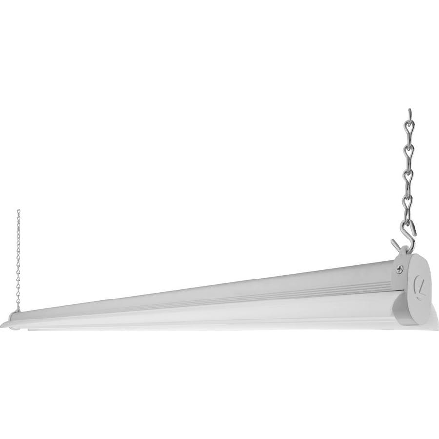
I didn’t want to replace them with anything expensive, so I decided to continue with some cheap $20 hanging fixtures that I got from Lowes. I had good luck with a couple of these cheap lights from Lowes and manufactured by Lithonia. They actually are an integrated unit: you can’t change the bulbs out, they simply run until they are dead, and then you replace them. They are nice and bright, and I had installed two of them a couple of years ago with no complaints. They are also incredibly lightweight (which could also be considered as “flimsy”) at a weight of 1.7lbs. Ironically, they are listed as “4ft” bulbs, but the fixture length is a little over 45 inches. I purchased four more of these, and hung two of them immediately, with the other two waiting until I can get rid of some telescope grinding equipment. I just used wimpy hooks to attach them to the rafters, but the hooks have too fine a thread to be secure in just dry wall. I’ll have to get a couple of dry wall anchors to fix one in the place I intend.
At about 36 watts a piece, I now burn about 150ish watts for lighting in there, but the garage is actually bright and easy to work in. Huzzah.
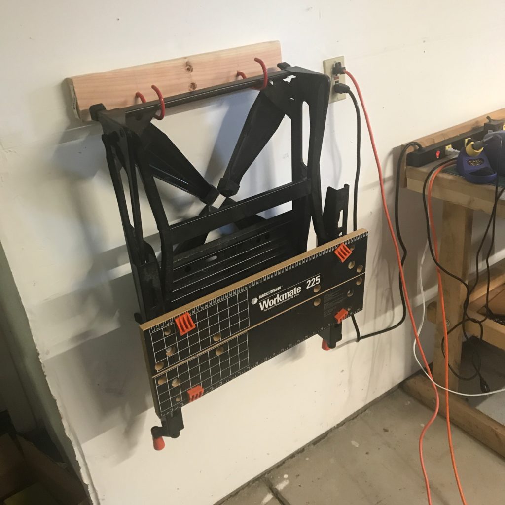
Addendum: I also decided that my Workmate rack of yesterday wasn’t entirely adequate. Because it was only fastened to the wall in the center (that’s the only convenient stud to attach it too) it actually looked like it could twist a bit (the wood is soft and the lever arm is relatively long). I decided to change the simple cross bar into a T shape. I took out my Kreg pocket hole jig, and bored two holes in the end of another scrap, and then fastened it to the original crossbar with glue and pocket screws. I drilled a couple of holes along its edge with a Forstner bit, and then fastened it back (a little bit lower) on the wall. Now, since it has fastening bolts along 2 feet of stud instead of just a couple of inches, it’s rock solid.
So, today I had a list of a few simple tasks in my garage that I thought would be good to get to. It’s now 2:30 in the afternoon, and I’ve… gotten some of them accomplished.
Just to the left of my door as I enter my garage, I had assembled a fairly rickety looking (but probably fairly sturdy) set of sheet metal shelves, and over the years they had acquired a thick layer of pointless crap and a few things that were actually worthy. In particular, it was the resting place of my old Philips 25Mhz oscilloscope, which I hadn’t used since I purchased my relatively spiffy 100Mhz Rigol scope a few years ago. Still, it works, and I thought that perhaps it would be a worthy contribution to our maker lab at work, so I dusted it off and set it aside, and then cleared the shelving unit. The amount of usable stuff was approximately what could fit in a shoe box, the rest was put in a garbage bag and will be gone on garbage day.
I drug the shelving unit outside and had a good look. It’s actually in pretty good shape, and while I don’t have space for it immediately, perhaps relocating it and using it for gardening supplies would be a good idea. I’ll ponder that some more.
In the mean time, I thought it would be good to find a way to hang my trusty Black and Decker Workmate 225. It’s a useful gadget, but it often ends up where I trip over it, or buried under other things. I thought I would just use a pair of bicycle hooks to attach it to the wall, and ordered a pair from Amazon Prime. Sadly, on the day it should have been delivered, they reported it lost and today I see that they refunded my money. But, my sweet wife went out and got me a set of 10 utility hooks from Target which worked out well. I found my good studfinder, and went looking for a stud in the place where I had removed the shelving. I found a scrap of 20″ long 2×4 and put two pilot holes into it, and inserted the largest curved hooks into it 10″ apart. I then predrilled a pair of holes in the middle so I could fasten the board to a stud, and drove it in using some 2.5″ construction screws I had left over from my workbench project. Voila!
The Workmate is now on the wall where I won’t trip on it.
It’s not the greatest bit of carpentry, but it gets it out of the way.
There has been a steady decrease in the amount of crap in my garage, but it’s still fairly crowded. Sometime in the next month I hope to get rid of my old telescope grinding machine. which should free up a couple of square yards of space. I have someone who wants it, but we are trying to arrange a suitable time to hall the monstrosity off. In the mean time, I still have a lot of crap and only a little space.
Some of it was being taken up by a tangled pile of hose and cords which was my Weekender power washer. I decided that I needed to figure out a way to get it all back in its case, which meant disassembling some fittings that I hadn’t done in ages, and which had resulted in me piling it on a bench earlier. I tried looking up the manual, hoping it would provide some hint, but it appears that the manufacturer has gone out of business, so I wasn’t able to figure it out. A little poking and prodding got most of the hoses disassembled, but the spray gun itself was a little odd. I ended up pulling a bunch of screws and disassembling it. Future me might want to remember this little tidbit: to get the spray wand off the handle, push in and twist. I suppose it should have been obvious, but it took disassembling for me to figure it out.
I’ve taken to making photographs of the make and model number of new tools that I get and uploading them to my Google Drive account. Along with their manuals (which I scan using my Brother scanner/printer and upload to Google Drive) I have found this to be really useful. Just for fun, here is a look at how all the parts go back in the case, along with the ID tag for the power washer:
How I squeezed it back in the box.
It’s a model H90.
The truth is that if I have any problems with it in the future, I’m likely to replace it anyway, since it’s not the most glorious power washer anyway. But for now, it’s back in its box and stashed on storage shelves until next time.
I did some more vacuuming. I might go out and replace two old set of ballasted fluorescent lights with some new (and much brighter) LED lights, but overall I think today might be done.
Oh, and by the way, this marks the first time I used my new DeWalt drill and driver. Both are really powerful! I will have to get used to them. I used the drill to do the pilot holes in my 2×4, and it was insane how quickly it punched through the 2×4. The torque of these brushless motors is freakin’ amazing. It really pointed out that the drill bits I have are dull, because it did have a tendency to skip around. I should probably get some new drill bits (perhaps even some bradpoint bits) and get a bit more practice to keep the drill from wandering away from the mark (or punch a small divet using an awl). The impact driver was amazing. I drove these 2.5″ screws into the wall stud without a pilot hole with no problem at all. Definitely need some more practice in the brave new world of power tools. I think I am glad I still have my wimpy little 6v Black and Decker drill for less aggressive uses.
When I was a kid, I went through a phase where I was really interested in model railroading. Like most boys, I had an inexpensive toy train set that ran around on the carpet until someone stepped on it, swore, and then I had to pack it away, perhaps making another appearance around Christmas. But I read Model Railroader magazine and gawked at the magnificent layouts that people had, perhaps taking up the entire basement, with hundreds of cars, and beautifully sculpted trees. In particular, I liked the romance of steam locomotives, and to this day I find trains to be pretty interesting.
Recently, one of my Facebook friends mentioned that Rod Stewart was a model train enthusiast. Calling him an “enthusiast” is damning him with faint praise. He apparently built a lot of his incredible layout in hotel rooms while touring. Judging by the pictures, it’s really amazing.
But back to me…
I don’t have the room, patience or skill to aspire to anything that could even be listed in the same breath as his, but I began to wonder: what could I really achieve? Could I build a small but interesting layout using reasonable time and budget? I’ve been acquiring some wood working tools that makes the benchwork easier to achieve, and while my house is crowded with all sorts of crap of my own, and my modelmaking skills (which never were amazing) are pretty modest, so would it be worthwhile to tackle a new project like this?
So, I did what I always do. I hit the web to look for inspiration, and to refresh what knowledge I used to have but may have forgotten.
First, gauge. All of previous toys had been either O or HO scale, but I had definitely preferred HO at the time, as my layouts were always space constrained, and HO gave me enough space so that I could put some switches in. But in considering possibilities for a new layout, I’ve begun to consider N scale, which is a little over half the size. The locomotives are positively diminutive, but it does mean that a layout which would be 4’x8′ in HO can probably be squeezed into a much more manageable 2’x4′ layout, which seems really attractive to me.
But what could I really accomplish on such a small layout? I didn’t know, so I went out looking for inspiration. And I found it in abundance on the All Gauge Page at thortrains.net. As it says, it contains tons of information about layouts of all gauges, sizes and interests. But what I found most helpful were some of their layout designs like this page full of N scale mini layouts. What’s especially cool is that they include lists of all the track that you need to construct them. There are a bunch of other nifty small layouts here as well as well as many others. There is a ton of information here. I haven’t begun to scratch the surface.
Simple loop with just one siding. Still cool though, and lots of room for scenery.
Something as small as this could still be interesting. At just 2’x2’6″, I could easily imagine constructing this entire layer as part of a small coffee table with a glass top, which would both protect it and make it serve a dual purpose.
I’ve no idea whether this will stick in my head as interesting, but for an evening at least, it was pretty interesting to think about.
Previously I had written up a bit on my project that I have called my “solar satellite station.” I used quotes around the word “solar” in the title because for the past couple of months, it has mostly been sitting on my workbench in my garage, occasionally powered up by a 12V charger rather than the sun. My hope is to get it out into the sunshine fairly soon, but that’s rather waiting on a couple of changes to the software. Most importantly, it consumes rather too much power than I would like which I suspect is that it runs continuously, even though it samples the data (temperature, pressure and current) only periodically. If I utilized the deep sleep mode of the ESP8266, chances are excellent it would reduce the power consumption by a factor of ten or more.
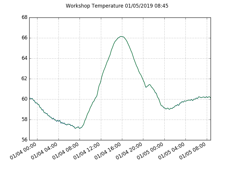
But that is a post for another day. Today, I thought I would bore you with graphs from the data that I’ve been logging. Currently I have detached my charger, so it has been running from the battery power (a 7.2Ah lead acid battery, if you haven’t been following along). First, the temperature in my garage:
It’s not exactly warm in my garage, but it is south facing, so when the sun comes up I get about a 10 degree boost in temperature.
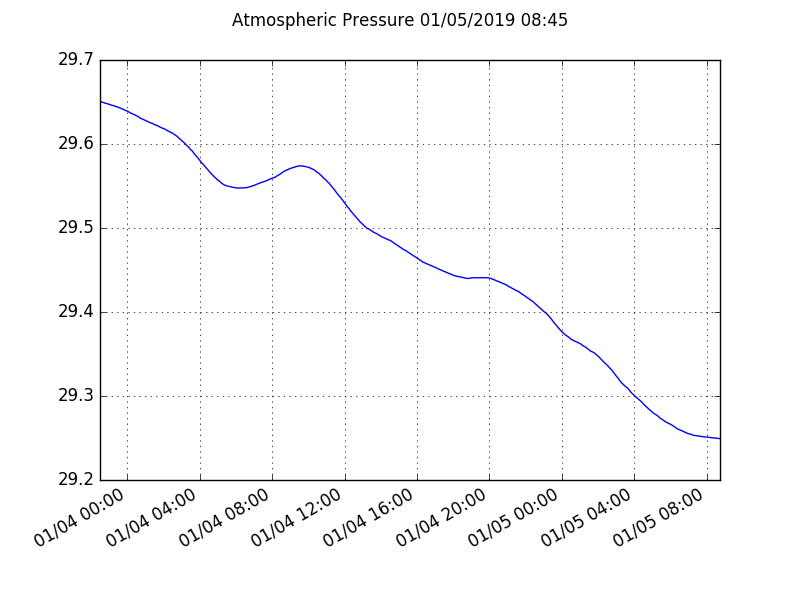
The skies were clear last night, but we are expecting some rain today (indeed, it’s already begun) and we don’t have much sun today, so I would expect it to be a bit chilly. On to atmospheric pressure:
Pressure has been dropping pretty significantly over the last 24 hours.
This was sensed with the MPL3115A2 sensor from adafruit. This is about as significant a drop as I’ve seen in recent memory. The prediction is that we are going to see three or more inches of rain in the next couple of days. Neat.
Now, onto power and current consumption. I have separate INA219 voltage/current sensors monitoring the lines to the solar panel as well as the battery. The “solar panel” in this case is currently an unplugged charger. As you can see the current is zero amps, so the battery is not being charged at all. The voltage has dropped by about half a volt in the thirty six hours or so that the graph spans. The voltage is actually pretty much equal to the battery voltage, since the charge controller has a common positive between the panel and battery circuits. Power is the product of voltage and current, and is of course zero as you would expect.
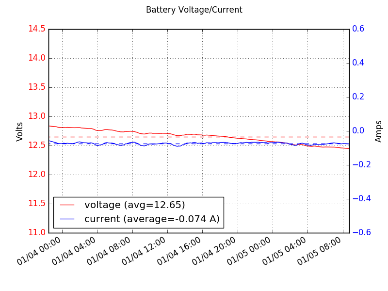
Moving on to the battery side of things:
The battery side indicates the total consumption of all elements of the system. You can see that it’s average about 74 milliamps at 12.65 volts, or about 936 milliwatts. This is the combined consumption from the charge controller and its inefficiencies, as well as powering the two ESP8266 (one is still being used as a serial bridge for debugging) and all the various I2C sensors. If we call that 1W, then we can estimate the total capacity of the setup pretty easily. The battery is a nominal 12V at 7.2Ah, or 86.4 Watt/hours. That means that we’d discharge the (large and rather heavy battery) in under four days. Since I really want the battery to be discharged no deeper than 50%, a couple of days is probably all it can really take.
I know I can do better. Currently it’s maintaining two processors, each with their own WiFi connections. If I removed my debugging one, power would immediately drop by half. And I really need to get back to using deep sleep mode. I prototyped a deep sleep version of the code that just sent temperature, but I haven’t worked on deploying it yet. I also want to shift to using my own MQTT server. Perhaps we’ll get to it this weekend. Until then, I’m off into my garage to cut up boxes for the recycling bin. Have a good weekend, all.
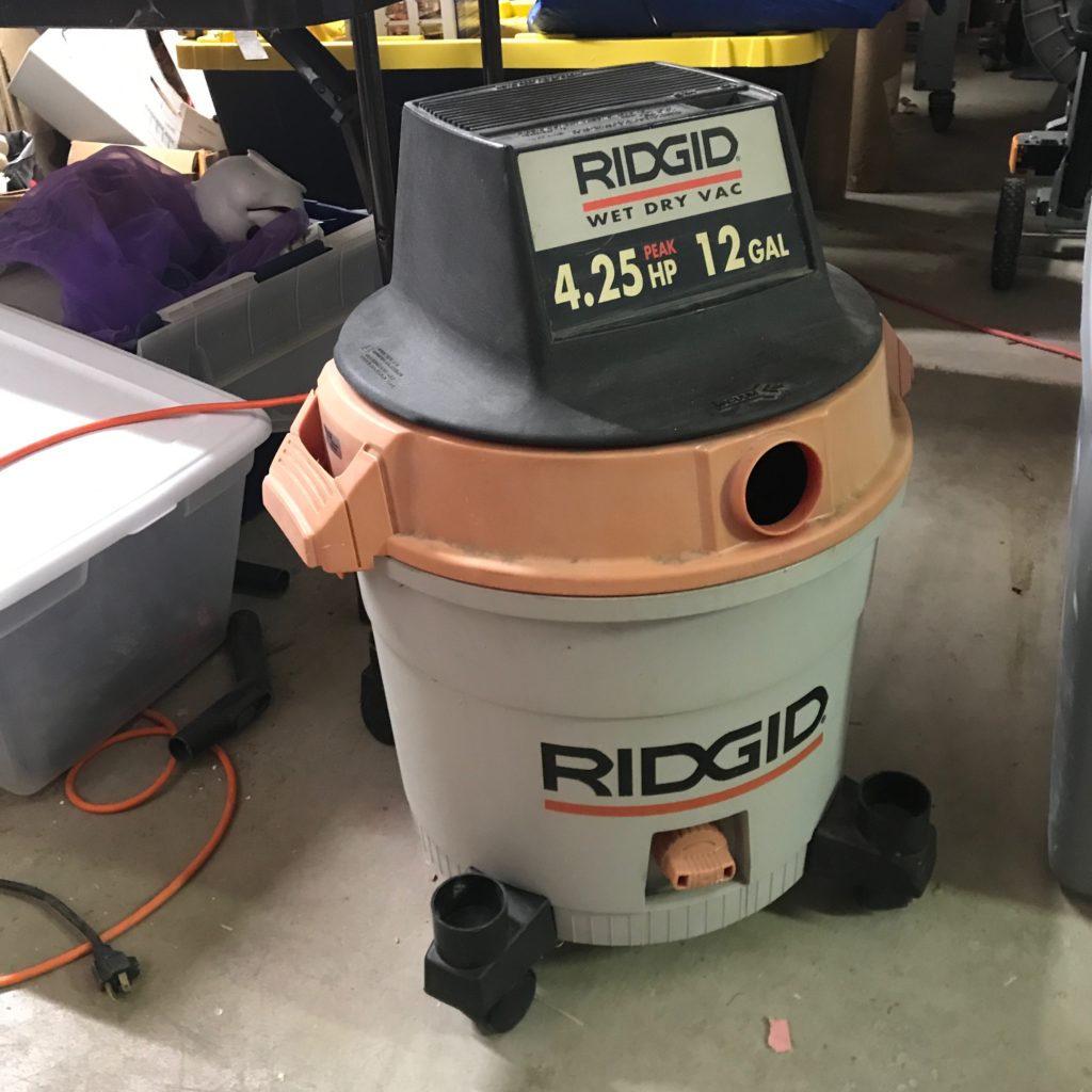
Okay, this doesn’t really count as a hack or anything, but it is a tiny bit of virtuous behavior: I fixed an old Rigid 12 Gallon shop vac that I had sitting around. I hadn’t used it in a while, probably a few years when I had a water leak in my garage this summer. I used it to suck up some water and gook, but noticed that the switch on it had broken and it was jammed in the on position. I could still turn it on and off by unplugging it, but that wasn’t super convenient. I also noticed that it didn’t smell particularly great, with a slight “motor burning out smell”, so I set it aside until last weekend.
Before Christmas, I disassembled it to see how difficult it would be to repair. First of all, I noted that the filter was… well beyond disgusting. Clogged, dirty, it would be truly surprising if any air got through it at all. I removed it, and then disassembled the top of the vacuum. I found that the switch was actually a pretty easily replaced item: made by Carling Technologies, it was held in place by a couple of clips, and wired to the power line with a couple of slide on spade connectors. The glue-on label for my vacuum had long since departed, so I wasn’t able to find the exact model, but it appeared that the switch in many similar models was officially discontinued. But a little searching on line yielded this switch, which appeared to be the same size and had a similar clip structure. Unlike the original, it was a rocker style switch instead of the “bat” shaped one it came with, which was fine with me, as those switches seem to break more easily in my experience.
Got the switch today, fitted it in (worked perfectly) rehooked up the switch and plugged in the vacuum. I had pressure washed the can, and had removed the bad filter. Turned it on, and… it works! Huzzah. Of course I installed the switch in backwards, so the “ON” position is actually off, and “OFF” is on, but I don’t feel like unscrewing it just to fix that. While running it, I could smell a hint of what I smelled before, but I left it running for about five minutes, and the scent seemed to fade, but I am not sure if anything is wrong. Perhaps a little lubrication is in order, I’ll have to look it up. In the mean time I’ll get a replacement filter. I suspect I’ll get a few dollars worth of use out of it anyway, and I may as well use it until it’s dead.
It will get some use to get rid of some dirt and grime in my shop this weekend.
Addendum: Matthias Wandel (in addition to being a fascinating woodworker to watch on YouTube) had this nice video on oiling the bearings in your shop vac.
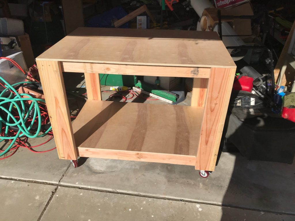
Okay, I never have been much of a woodworker, and haven’t done anything significant in a decade or so. But as I’m trying to clean my garage workshop and get things tidy and in order, I have decided that it would be both cost effective and fun to construct some crude workshop furniture. I got myself a Kreg pocket hole jig and a new miter saw over the Christmas holiday, and decided to go ahead and try to make a rolling cart that I could use to store some items like my combination disk/belt sander and vacuum cleaner for dust collection, as well as possibly provide some additional mobile work surface.
Skipping to the end, a short day in the garage yielded this cart:
Not perfect, but functional.
I’m generally happy with it, but I did have a few notes/criticisms about the general construction that I’m going to keep in mind for future construction projects.
I went to home depot to buy four 2x4s and 2 2x6s to form the frame and risers. They didn’t seem to have dried lumber in 2×6 form, so I built this out of green Douglas fir. The lumber was fairly straight, but the moisture content was probably somewhere north of 18%. I could have let it dry out over time, or gone in search of dry lumber somewhere else, but I was impatient, and decided that using green lumber would probably be fine. Indeed, I think it will be fine, given the crudity of my carpentry skills.
The frames were assembled with pocket screws, which I seemed to have mixed results with. I think in at least one case, I stripped a screw by over tightening. Perhaps I should get a better drill with a proper torque clutch.
The rest of the frame was screwed together with 2 1/4″ deck screws with a star drive. This worked rather well. I didn’t drill pilot holes. I will next time, I think in at least one case where I screwed one in near the end, I got some splitting.
I used 3″ locking casters from Harbor Freight, which worked well. I fastened them down with the same #10 2 1/4″ deck screws, but with a #10 washer to help center them. I did predrill those holes, and managed to snap a drill bit off doing one. Note to self: get some better drill bits.
I made the table taller than the original design, and noted that the top had a bit of flex front to back. After the table dries out a bit more, I’ll probably screw a board across both sides, or maybe some thin sheet plywood to stiffen it up more. It’s plenty strong for storage, but if you were going to use it as a platform for power tools, the vibration may not be good.
For quickness/expedience, it’s held together with just screws: I didn’t glue any of the joints. That ultimately limits the strength and rigidity. If I get a small table saw, I’d probably rip them more square and put some half lap joints in, and do a proper gluing job. But for now, it’s fine.
Anyway, the plans are available on the Kreg website. The only modification I made was to make it a bit taller to match the height of my other bench and to match the casters that I had on hand. It was a good refresher project, and the first time I used pocket screws. I’ve got some other projects in mind, so stay tuned.
Okay, as part of my ongoing attempt to clean my garage (“Project Virtue”) I called up some friends from the Chabot Telescope Maker’s Workshop. I had a pile of telescope making supplies that frankly I’m not going to live long enough to use effectively, and I thought that I would try to get rid of some of this stuff. They ended up hauling away a bunch of tubing, some blanks (both totally raw and some ground) and various bits of hardware like focusers and mirror mounts.
Frankly, I was hoping they would haul away more, but it appears that I’ll have to do some work to get rid of some of the more “specialty” items. I’ll probably write up some of the others later, but today’s post will focus on this:
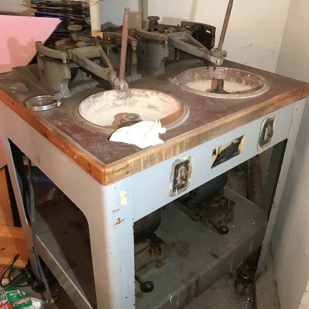
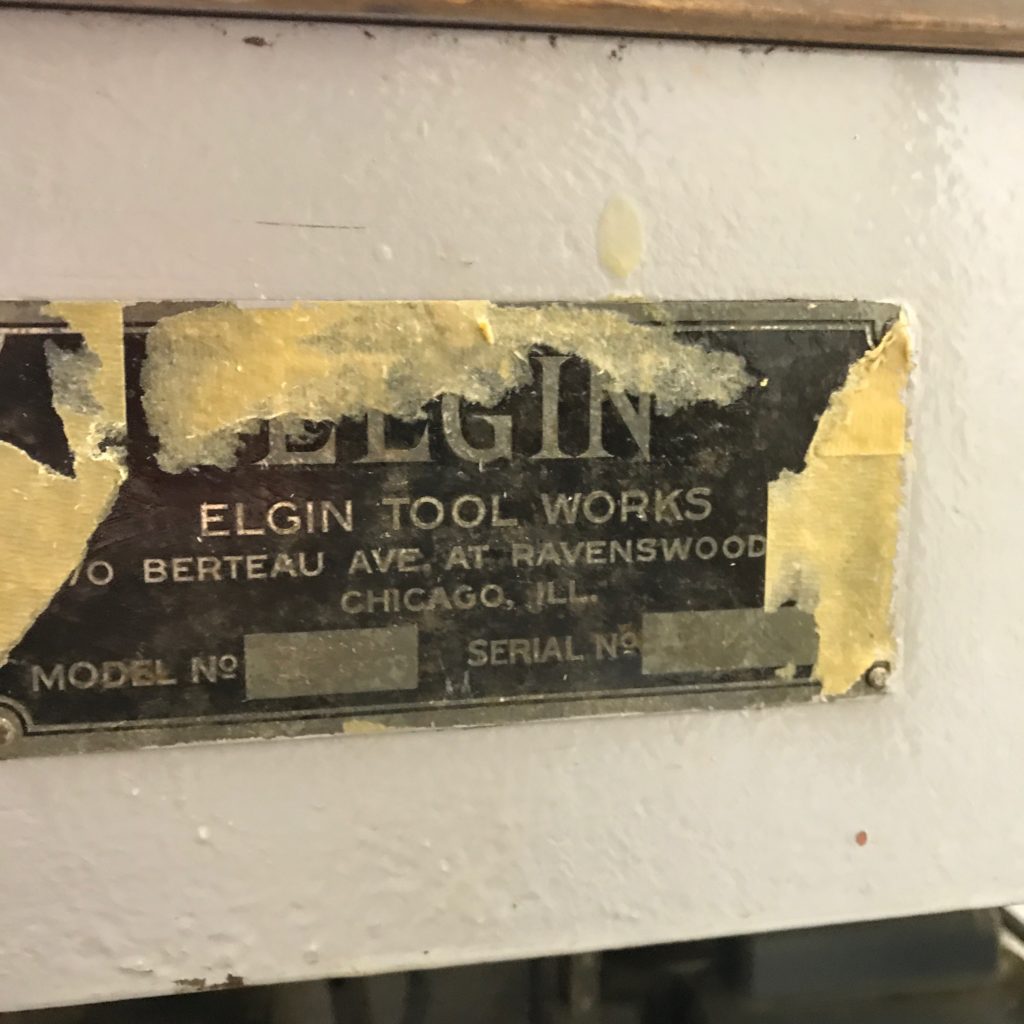
Elgin Model No. 2-12, Serial Number 9120
The numbers are hard to read, but here is the ID plate
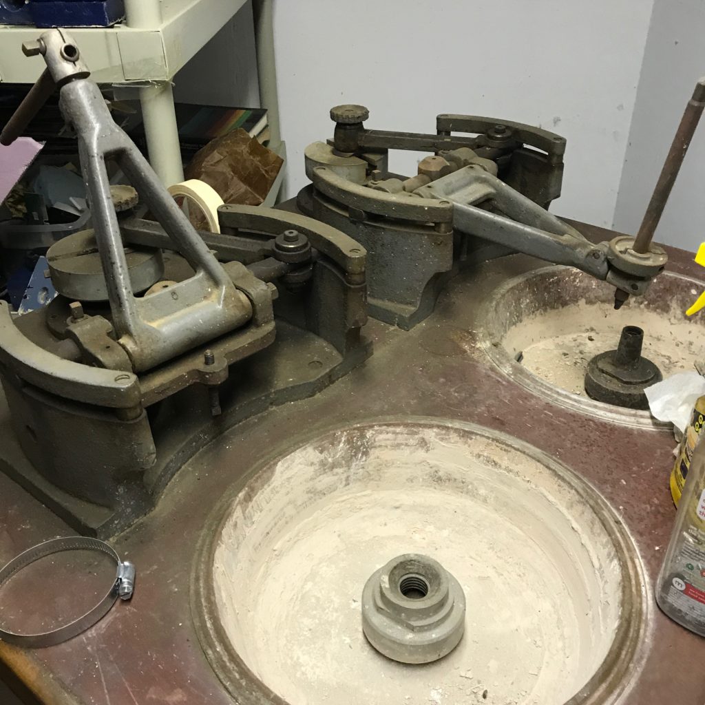
Two spindles…
This is an Elgin Model No. 2-12, Serial Number 9120. What, you may ask is that? It’s a dual spindle grinding machine for making optical components. This machine was in the Telescope Maker’s workshop at the old Chabot Observatory where it sat mostly unused for years (I can’t remember anyone actually using it) and when the telescopes were moved to the new science center location, I decided to save this machine from the junk pile, and took it. My guess is that it probably dates to the 1940s or so, but I could be wrong. I’ve been unable to find any information about the machine (feel free to contact me or comment if you do know about them.)
It is amazingly, ungodly, heavy. When I naively said I would take it, I went over to the machine and have it a hard push on one corner. It didn’t budge. So, think I, “it must be bolted down.” Uh, no. It wasn’t. I never weighed it, but it’s got to be north of five hundred pounds. It is astonishingly heavy and sturdy. Luckily, when I took possession, my friend Ken welded some heavy casters on the bottom so that it was possible to wheel the machine around. I recall he also donated the use of his heavy pickup to bring it home. Where it has sat ever since.
It has two spindles, each powered by a separate motor and having a separate power switch. I hesitantly plugged it in and with some hope gave the switches a flip. First, the good news: the right spindle fired right up. The bad news? Not so much for the left spindle. I can hear a faint electrical whine, so I suspect it might be something as simple as a starting capacitor for the motor. I haven’t investigated further.
So, here’s the thing: does anyone want this thing? Realistically, I’m not going to invest the time and energy to get this thing tuned up in and in use, so I’m looking for someone to give it a new home. If you can spin me a good story as to why I should give it to you so you can make cool stuff with it, and show up with a U-Haul, some straps, and a ramp and some burly friends to help out, I will almost certainly let it go for free. I live in El Sobrante, CA, so this is probably of interest mostly to people in the SF Bay Area, but perhaps people farther afield might be interested.
Feel free to pass links to this post anywhere you see fit. Contact me via email, or my twitter handle @brainwagon.