Category Archives: Arduino

A few more notes on my implementation of Conway’s Life…

I received a couple of email and twitter queries about various aspects of the code, so I thought I would add a followup to yesterday’s post.

First of all, I received a query as to whether it was “open source”. Frankly, the code is so minimal and so obvious I didn’t even consider it worthy of protection from any license. Consider it in the public domain. I do appreciate it when people who use this code give a nod back to my website as the origin of the code, but it’s not mandatory.

Seriously. It’s not a big deal.

Next, realize that I wrote the code in just a few minutes (less than thirty). It’s written in just about the most obvious way I could conceive. I really was just looking at a way to test my understanding of the U8glib library, and this seemed like a good way to go. There are a number of ways the code could be improved.

First, this implementation doesn’t use the full resolution of the 128×64 display: it only uses 96×64. The reason is quite simple: the way the code is written, it needs to maintain 2 buffers (the “current” and “next” arrays) each of which hold 128×64 bits. If you multiply out 128x64x2 and divide by 8 to get the number of bits needed, you’ll come up with 2048: coincidently, exactly the same amount of RAM in an ATMega328. But you’ll need some extra memory to hold temporary variables, buffers used by the U8glib, the stack for subroutine calls, etc… Trimming the resolution back to 96×64 provides enough space to actually run. But we could actually use the full resolution by being slightly more clever: instead of having two full size arrays, we could do more of the updates “in place”, and only buffer a couple of extra lines to hold out temporary values before we overwrite them. I have the code in my head, but a few odd details about it aren’t worked out yet, I hope to have nearly as simple an implementation worked out today some time. Stay tuned.

Second, it’s slow. Doing 8 independent bit lookups in the array, the increments, and the compares? It’s a straightforward implementation, but not a fast one. In particular, the shift operations on every pixel lookup are probably really a bad idea on the Atmel AVR: these chips don’t include a barrel shifter, so to shift by 7 takes 7 cycles. We could probably factor out a lot of these calculations with some work. It’s possible to use techniques that can process all the bits inside a given word “in parallel” by implementing bitwise arithmetic, but since the AVR is only an 8 bit processor, the gains are less than they would be on a 32 bit processor, and handling all the edge cases is kind of a nuisance. I remember doing this back in my college days, but I’d have to work out all the details again. You can look at this article from StackOverflow to get some hints and pointers to other implementations. Some of the ideas are good, some not.

Third: the display is really, really tiny. It might be fun to use the builtin scaling of the U8G driver to magnify it by two. Then, of course, we’ll only need to do 64×32, which should run around 4x as fast, and should be easier to see. It will also use a lot less memory, which makes it more useful as a module in (say) another program like a DIY watch.

Lastly, I was told that initializing the random number generator in this way would work, but it seems to generate the same seed each time. I’ll have to figure out a better way to initialize the seed on RESET.

Stay tuned for an improved version.
Tiny Implementation of Conway’s Life…

I had a few minutes, so I thought I’d try making a graphics demo that runs on the tiny little 0.96″ OLED display I mentioned last week. One of the first programs I ever wrote was an implementation of Conway’s Game of Life, having learned about it from Martin Gardner’s Mathematical Games column in Scientific American. I remember that on my old Atari 400, it took a couple of seconds at least per generation, at a resolution of just 40×20 or so. Because of the limited memory (and small size of the display) I decided a 96×64 resolution. There is just enough memory to handle two full sized bit buffers. With a bit more work, I could make it work at the full resolution of the OLED display, but you need to do some of the updates in place, which makes it a bit harder.

[sourcecode lang=”cpp”]
//
// a tiny implementation of Conway’s Life
// written by Mark VandeWettering (brainwagon@gmail.com)
// https://brainwagon.org
//

#include "U8glib.h"

#define XSIZE (128-32)
#define XSIZE_UINT8 (XSIZE/8)
#define YSIZE (64)

uint8_t current[YSIZE][XSIZE_UINT8] ;
uint8_t next[YSIZE][XSIZE_UINT8] ;

#define MODX(x) (((x)+XSIZE)%XSIZE)
#define MODY(y) (((y)+YSIZE)%YSIZE)

#define ISSET(a, x, y) \
(a[MODY(y)][MODX(x)/8] & (0x1<<(MODX(x)&7)))

#define SET(a, x, y) \
a[MODY(y)][MODX(x)/8] |= (0x1<<(MODX(x)&7))

U8GLIB_SSD1306_128X64 u8g(U8G_I2C_OPT_NONE);

void
init()
{
int i, j ;
for (j=0; j<YSIZE; j++)
for (i=0; i<XSIZE_UINT8; i++)
current[j][i] = random(256) ;
}

void
setup()
{
randomSeed(analogRead(0));
init() ;
}

void
draw()
{
u8g.setDefaultBackgroundColor() ;
u8g.drawBox(0, 0, 128, 64) ;
u8g.setDefaultForegroundColor() ;
u8g.drawXBM(16, 0, XSIZE, YSIZE, (const uint8_t *) next) ;
}

void
loop()
{
int i, j ;

memset((void *) next, 0, sizeof(next)) ;
for (j=0; j<YSIZE; j++) {
for (i=0; i<XSIZE; i++) {
int sum = 0 ;
if (ISSET(current, i-1, j-1)) sum ++ ;
if (ISSET(current, i , j-1)) sum ++ ;
if (ISSET(current, i+1, j-1)) sum ++ ;
if (ISSET(current, i-1, j )) sum ++ ;
if (ISSET(current, i+1, j )) sum ++ ;
if (ISSET(current, i-1, j+1)) sum ++ ;
if (ISSET(current, i , j+1)) sum ++ ;
if (ISSET(current, i+1, j+1)) sum ++ ;

if (ISSET(current, i, j)) {
if (sum == 2 || sum == 3)
SET(next, i, j) ;
} else {
if (sum == 3)
SET(next, i, j) ;
}
}
}

memcpy((void *) current, (void *) next, sizeof(current)) ;

u8g.firstPage() ;
do {
draw() ;
} while (u8g.nextPage()) ;
}
[/sourcecode]

It works! It initializes the display to random values, and then runs Life. If the display gets boring, just hit the result button….


My first try at an inexpensive 0.96″ OLED display…

As my recent video showed, I have a lot of development boards. I also have a fair number of little boards that are useful to plugin to these development boards to accomplish various tasks. Yesterday, I received a little OLED board that I thought I’d try hooking up and let you know about my experience.

There are lots of boards out there that apparently use the same screen: a 0.96″ OLED display with a resolution of 128×64. I ordered this one from Amazon for only $9 with free shipping. The description is a little bit misleading: you can find versions of these kinds of boards that have 7 or 8 pins and use the SPI bus. This one has (and requires) only four pins, and uses the I2C bus. I’m no expert on the technical differences, but my general impression is that SPI is full duplex and can run at higher speed and at longer range, but requires individual chip select lines for each device, where the I2C bus uses chip addressing, so no additional wires need to be hooked up to select the proper target device. (If any of my genius readers care to correct me on that, feel free to leave a comment).

Here’s a picture of the module I got, as I tweeted it yesterday:

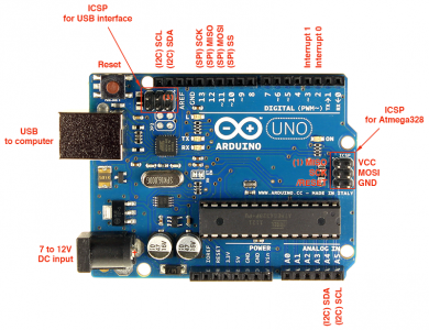
It’s safe to run on either 5v or 3.3v, without any level converters or other nonsense. I hooked it up to one of my Sparkfun RedBoard Arduino clones. I plugged it into a bread board, and then wired up the four connections. VCC goes to the 5V pin on the Redboard, GND goes to one of the Arduino grounds. The remaining two lines need to be hooked up to the SCL (serial clock) and SDA (serial data) lines on the Arduino. This caused me a minor bit of confusion: on an Arduino R3, those two pins are on A4 and A5.

Uno R3 Pinout

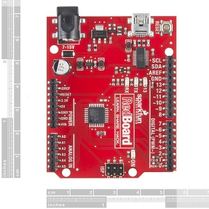
On the RedBoard, these pins are split out separately onto separate pins near the AREF pin.

Red Board

I connected them to the SCL/SDA connectors on the RedBoard. I suspect that on the Uno R3, A4/A5 are the connectors you’ll need. Other variants of the Arduino might need different pins.

And, of course you’ll need some software. It’s tempting to go to Adafruit for all things Arduino, but in this case it can be a bit of a mistake I think, or at least it might require a bit of tinkering. Adafruit sells their own OLED boards, but they are a bit more costly and are wired a bit differently, and I thought that might make their software a little trickier to configure.

Instead, I found the U8G graphics library. It’s fairly nice because it supports a wide variety of boards, and is self contained. If you download the Arduino code and unzip it into the Arduino library directory and restart the Arduino environment, you’ll see some examples installed. But if you load one and try to compile it, you’ll encounter an error: the examples aren’t configured for the particular board you need. To do that, you need to uncomment the right definition for the graphics device.

For this specific device, you want to delete the two slashes at the start of this line. This selects the I2C bus, and tells it to use the SSD1306 chip that is on the board. This one worked for me.

//U8GLIB_SSD1306_128X32 u8g(U8G_I2C_OPT_NONE);  // I2C / TWI

So, I downloaded the “Graphics Test” example, made that modification, compiled it and downloaded it to the RedBoard. Voila


A pretty neat little display. I must say that it’s a bit too tiny for my old-guy eyes to read when the print is small (damn you presbyopia!) but It’s very sharp and clear. If you have need of such a device, this one seems inexpensive and easy to use. Check it out.

A 6M beacon using the NT7S’s Si5351 board…

This morning, the Tweeti-verse (I can’t believe I just used that word) informed me that Thomas, LA3PNA had constructed a VHF beacon using the Si5351, and I was tagged as somehow helping:

Sure enough, I’m getting lots of mileage out of the very simple Morse generating code that I posted a while back. But the real star of this was Jason Mildrum (NT7S) and his awesome little Si5351 breakout board that he designed and made available via Indiegogo, as well as a nice little Arduino library to control the board. For those of you who don’t follow this stuff, the Si5351 is a nifty little board that is capable of generating three frequencies at once under the control of a microcontroller like the Arduino. Guys like Jason and Pete Juliani, N6QW, have been experimenting using this device as the basis for frequency generation in a variety of experimental radios. I received my kit last week, and hope to get the board up and running this week. Stay tuned!

A Big Bin Full O’ Development Boards at BrainWagon Labs…

I have an odd obsession with small, relatively cheap hardware development boards. Over the last few years, I’ve acquired a bunch of them, from Arduino to Raspberry Pi to BeagleBone Black. I thought it might be nice to just do a short video showing what I have around. So I did. Here’s a little 25 minute video demoing what I’ve got lying around.

Here’s a bunch of links to some of the boards I mentioned:

  • Arduino, the classic board. Based upon the ATMEGA328, an 8 bit processor, 32K of flash, 20Mhz. Great user community.
  • Beagle Bone Black Very cool Linux based machine.
  • Raspberry Pi Perhaps my favorite board, I don’t have the version 2 board yet, but the version B+ boards are really nice. I particularly like the Pi Camera boards you can use with them.
  • WRTNode A very cool, very cheap Linux box, with WiFi. Runs OpenWRT, a stripped down version of Linux, but still cool.
  • Wild Fire board A very nifty little board by Wicked Devices, who supplied me with a couple. During the video, I mentioned that I thought these boards were a bit expensive, but checking their website, I see them selling for about $49. If you need an Arduino compatible board with some extra punch, it’s a great little board.
  • ESP8266 The tiniest and cheapest board that I had. Often used as simple serial->WiFi chips, they are actually quite powerful and can be reprogrammed. This lua based firmware is a cool example.

Task completed: Evil Mad Science ISP Shield soldered together…

Last night, the absent-far-too-often urge to fire up the soldering iron and make something hit me, so I warmed up the Weller and did this:


I bought this kit quite a while ago, and it has been sitting on the shelf mocking me for a long time. It’s available from Evil Mad Science for a reasonable $13 or so, and is a very easy kit to assemble, consisting of a crystal, three caps, and seven resistors, plus some headers. My soldering skills are a bit rusty, but it wasn’t difficult, I had it done in a leisurely 40 minutes or so, including my hunt for some bare ATMEGA328s that I had stashed in a box somewhere.Arduino ISP Shield

If you aren’t really up on this, you might ask “okay, what does it do?”

Long time readers of my blog may remember that I had previously used an Arduino as a programmer, in that case to program some small 8 pin Atmel chips like the ATTINY13 or ATTINY85. These chips are too small to use the regular boot loader that is common on the ATMega328 chips that are used on the Arduino, so you need to use the ISP (or In System Programming) method to get software onto the chip. If you want to program the Arduino bootloader onto a bare ATMega328 chip, or write software directly to such a chip, you also need to use the ISP interface. If you have a breadboard, you can pretty easily set up the programmer, but it’s a little inconvenient: I have to look up all the right jumper wires, double check them, maybe wire up a crystal oscillator, it’s just not fun. Hence, this shield. You plug it into an Arduino (I used one of my oldest Arduino Duielfoovena, whatever that word is) and flash the AVRISP sketch that comees with the Arduino software, and voila, you are ready to program. It has a nice ZIF (zero insertion force) socket, which allows you to insert your 28 pin DIP (either a ATMega328 or ATMega168) and has four LEDs that can serve as status indicators. If you want to burn a bootloader onto a chip, you select the “Arduino as ISP” Programmer type, and then tell it to burn the bootloader. Voila!

The ISP also includes the classic six pin header that you can use to jumper to any Atmel board that provides such a header, and you can program the chip inside the system, including non-DIP versions.

So, why would you want to do this?

Well, you can build your own Arduino compatible boards now, for much less than what you would typically pay (although, perhaps not cheaper than you could pay getting them from China). A bare ATMega328 costs about $3.50, which isn’t super cheap, but it won’t break the bank either. Add in a little 5v or 3.3v regulator, two caps and a crystal, and for less than 5 dollars in parts you can put together a homebrew microcontroller than you can program with the Arduino environment. Pretty useful if, say, you wanted to embed a little microcontroller in a radio project you wanted to try.

Apologies for the long gap between posts. I’ve got more stuff in mind, I’ll try to get back to doing more stuff and blogging more stuff.

FTDI-gate…

My hardware hacking friends have been all a-twitter (and all a-pick-your-favorite-social-platform) about recent actions by FTDI. In case one of my three or so regulars haven’t heard about this dust-up, here’s a brief synopsis.

  • FTDI makes a series of chips which translate between USB and either RS232 serial or TTL level serial signals. These chips are used in (among many other devices) many types of Arduino boards and many USB dongles that are used to program them.
  • Because of their popularity, clones of these chips have been created. These chips are not simple copies, but functionally equivalent replicas, designed to operate the same as FTDI’s chips. There are benefits to this: since they operate the same as FTDI chips, they do not require separate drivers. They are also drop-in replacements for existing designs.
  • Because they are drop-in replacements, unscrupulous parts distributors have “rebadged” this clone chips as the genuine article. These chips are genuine counterfeits. But in many cases, the buyers of these chips have idea that counterfeits have been substituted for the genuine article.
  • Microsoft Windows has a mechanism that automatically updates operating system components (including device drivers) automatically. These updates, annoying as they are, are necessary to patch security vulnerabilities. FTDI releases driver updates as part of these regular updates.
  • FTDI decided to crack down on counterfeits. They released a new driver which attempts to detect non-FTDI chips. When it find ones, it disables the chip by overwriting the USB PID (the coded indentifier used by the USB system to find the proper driver for the device) to zero. This effectively keeps the USB system from using the device: it’s dead. Moving the device to any other machine (Mac OS X, Linux) doesn’t help either. The device is essentially bricked.
  • Note: while it is illegal to rebadge a chip and make it seem to be a genuine FTDI chip, clone chips are not illegal. The FTDI update does not attack counterfeits: it attacks clone chips. This puts all the pain not on the people guilty of fraud, but directly on end users, who have no way of even knowing if an FTDI chip or counterfeit is even in the product that for some reason, mysteriously stops working.
  • Because this update occurred as part of the silent windows update process, it now causes end-users to question whether they should accept updates. This is very, very bad for security.

FTDI: you screwed up. Big time. I know a number of people who manufacture goods using your chips, and they are scrambling to find alternatives because you have destroyed the trust relationship that they have with their customers.

Their reaction via Twitter has been equally without clue. To whit:

ZDNet’s article on FTDI debacle.

I was actually considering using an FTDI serial chip in my revision of my Minima project. Now, I’m looking for alternatives. Way to shoot yourself in the foot, FTDI.

Addendum:

From my twitter feed:

Nifty Arduino/AVR hack: measuring VCC

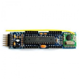
JNv4Assem_sq-450x450In my previous article pondering sensors for my garden, I shamefully neglected a viable and interesting choice, the JeeNode JeeNode is available here in the U.S. from Modern Device. It’s sold as a kit, which is unusual, but not particularly scary to assemble. It’s just a few through hole parts. It’s a pretty bare bones processor, but does interestingly include a wireless module. It uses the RFM12B modules running on either 433 or 915 Mhz. But what really makes the JeeNodes interesting to me are that they abandoned the (I submit) broken shield model of Arduino shields, and instead group the output pins for the Arduino into a collection of identical Ports which can be accessed using their JeeLib library. Each port consists of six pins (one ground, one Vcc, and four data pins) and all can be used to implement an I2C bus in software to access peripherals. Very cute, and much nicer than the hodge podge of existing code for the Arduinos.

But the website at JeeLabs has a bunch of other cool stuff. Like details on one of their JeeNodes that’s been transmitting data wirelessly for over eight months, powered by just a coin cell. Or this Dive Into JeeNodes which is a tutorial on interfacing JeeNodes to a Raspberry Pi to make a house monitoring system. While the blog isn’t being updated anymore, it includes all sorts of good stuff, including this rather clever article on VCC Measurement (a software only way for an Arduino to determine it’s own input voltage). Great stuff.

Pondering some sensors for my garden…

DSC_1941-500x500We’ve started a garden at our house in a pair of raised beds. I’ve been pondering about possibly creating a set of sensors to monitor the dryness of the soil in the beds as well as in the container that I have a dwarf Meyer lemon tree going in. I was trying to figure out what a good sensor would be. Ideally, I want a simple, low power computer, which is fairly cheap and easy to deploy. I’ve got more than a few Arduino variants around (Uno, Fio, RedBoards, Nanodes, and Wildfires) and they have more than enough horsepower to do what I anticipate (reading temperature, humidity and moisture settings) but there are two things that make them less than completely satisfactory to me:

  • They don’t have any kind of wireless link. You could certainly add one of several kinds, but…
  • That adds to an already fairly expensive board. Unos are about twenty five dollars. That seems like a lot. There are simpler boards of course, such as the Pro Mini. Sparkfun has those for about ten dollars.. You can also order Arduinos from Chinese manufacturers to drive the cost down, but a board cost of about ten dollars about the minimum you can get.

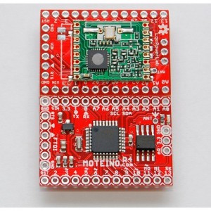
It seems to me that a complete node has a minimum cost of around $20 when assembled this way. It’ll include a Pro Mini, a small wireless board, and a couple of cheap sensors. Making the node solar powered would probably cost a few bucks more. But while digging around, I discovered that Low Power Labs had a really cool little board: the Moteino. It’s a very cool little board, offers a choice of different RF choices, and includes versions with and without USB. Do I really need another different Arduino clone?

Sigh. Maybe.

Moteino from Low Power Lab

My Arduino bumper, with actual prints!

Okay, our Replicator 2 went back online this week, and I decided to give printing my Arduino bumper another try. Since the last time, I have revised the program and code a couple of times. I was concerned that the various bits of solder protruding from the bottom of the board would need extra relief cuts. As I tried to account for more and more of these, I decided I did not like the design especially well, so I took a different tactic: I decided to make the bumper’s walls as thin as possible, and only include an area around each of the Arduino bolt holes. This minimized the amount of material needed, and also means that it could be printed more quickly.

And so, I printed it out. I use the Makerbot software, set for the Replicator 2, once using medium quality (with a print time of about sixteen minutes) and once using the high quality (print time of nearly an hour). I used 25% infill for both, I wanted to make sure the outer and inner shells were sufficiently bonded. I then printed it!


I had a little spare time, so I also decided to print out a simple model I made in OpenSCAD: a cross section of the Clark Y airfoil, with 1/8″ thickness. It turned out rather well, fairly smooth, and with only a minor divot at the trailing edge. It was also reasonably sturdy, I don’t think I could crush it in compression with my hand, although it’s impact resistance is unknown. I also took the time to download a model of the chicken from Minecraft and print that. It comes in four parts, which we could then glue together. I had no real failures:


But there were a few issues.

First of all, my Arduino bumpers were a pretty tight fit.

I coded in a clearance of 0.008″ around the nominal board size, but that was simply not enough. I think I’ll expand that to 0.012″ or even 0.015″ next time around. I was able to press fit one of my OSEPP Arduino boards into it, but just barely, and only by shaving a small amount off one corner of the board with an Exacto knife. I also think I should thicken the bottom slightly: if you used this shield to bolt against a conductive surface, some of the solder joints on the bottom of the board could still short out. I am also thinking of widening the channels cut for the USB and DC jack a small amount, they fit, but just barely. An additional 0.02″ of an inch would make them more comfortable. I also noticed that one of the prints had a corner which seemed to pull up and not be level/coplanar with the rest of the print. Not sure what that was about. But overall it worked! I’ll make these changes to the design, and then try another set of prints, and then you should be able to see it on Thingiverse.


I also printed this model of the chicken from Minecraft. It comes in four parts (body, head, two feet) which you can assemble and paint. The model is quite simple, I printed it with medium quality settings and 10% infill. It worked rather well, except that the parts do not assemble easily: the head is slightly too wide to fit into the slot in the body and the feet do not fit into the holes left in the bottom. I think a little judicious belt sanding will make the head fit, and I’ll measure and redrill out the holes to make the legs fit. But in general, the issue of clearances seems to be one I need to explore more. Does anyone have any good references/hints/guides they would like to share?

Another stab at an Arduino bumper…

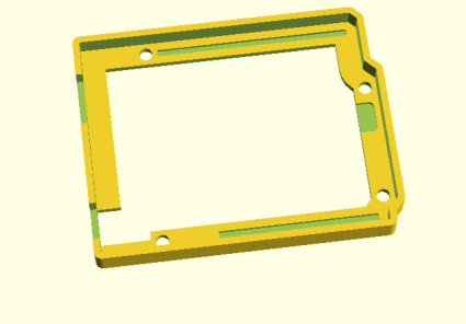
Earlier this week, I tried to print out the first version of my Arduino bumper. Sadly, our Replicator 2 had a malfunction mid print, and it’s still offline (a problem with the temp sensor) but that doesn’t mean I’ve been entirely stationary. I mentioned on twitter that I was having trouble using the minkowski operator to generate interior offset surfaces, and @kitwallace responded this pointer to some code he used which helped me generate a “lip” inside the outer wall that would snugly fit the Arduino. I also realized that this wall would bump into the backside of some of the pins, particularly around the DC jack, but also on the ICSP and header pins. So, I revised this a bit, and came up with this program:

[sourcecode lang=”cpp”]
module arduino_outline() {
polygon([[0, 0],
[0, 2100],
[2540, 2100],
[2600, 2040],
[2600, 1590],
[2700, 1490],
[2700, 200],
[2600, 100],
[2600, 0]]) ;
}

px = 2505.512 ;
py = 1198.031 ;

module icsp() {
translate([px, py-200, 31.25]) minkowski() {
cube([100, 200, 62.5]) ;
cylinder(r=50) ;
}
}

eps = 0.001 ;

s = 25.4/1000. ;

cl = 8 ;
th = 62.5 ;

module os() {
linear_extrude(height=250)
minkowski() {
arduino_outline() ;
circle(r=th+cl) ;
}
}

module is() {
translate([0, 0, -eps]) linear_extrude(height=250 + 2 * eps)
minkowski() {
arduino_outline() ;
circle(r=cl) ;
}
}

module final() {
difference() {
os() ;
is() ;
}
}

module neg() {
union() {
intersection() {
minkowski() {
difference() {
translate([-200, -200, eps]) cube([3000, 3000, 62.5]) ;
os() ;
}
cylinder(r=200+th+cl*2) ;
}
os() ;
}
final() ;
}
}

module holes() {
union() {
translate([550, 100]) cylinder(r=125/2., h=500, center=true) ;
translate([600, 2000]) cylinder(r=125/2., h=500, center=true) ;
translate([2600, 300]) cylinder(r=125/2., h=500, center=true) ;
translate([2600, 1400]) cylinder(r=125/2., h=500, center=true) ;
}
}

off = 31.25 ;
d = 31.25 ;
w = 31.25 ;

module relief() {
translate([1100, 100, 62.5]) translate([-w, -w, -d])
cube([1400+2*w, 2*w, 2*d]) ;
translate([740, 2000, 62.5]) translate([-w, -w, -d])
cube([1740+2*w, 2*w, 2*d]) ;
}

module slots() {
union() {
translate([-100, 125, 63+off]) cube([550, 350, 500]) ;
translate([-250, 1275, 63+off]) cube([625, 500, 500]) ;
translate([-cl, 125, 0]) cube([450+cl, 350, 500]) ;
}
}

$fn = 24 ;
scale([s, s, s]) difference() { neg() ; holes() ; slots(); relief() ; icsp() ; }
[/sourcecode]

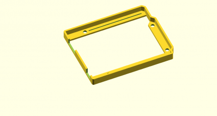
Here’s a quick picture:

bumperv2

It might be a few days before I can get this printed. If anyone uses this to generate STL and print it, I’d love to hear about what you think.

If not, stay tuned. I’ll get there eventually.

Arduino Bumper Shell, created with OpenSCAD

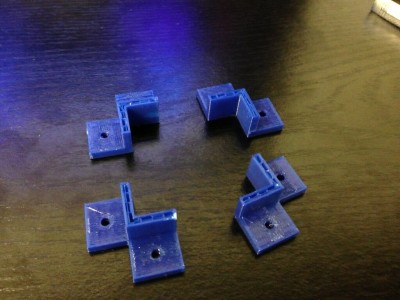
bracketsLast week, I got a chance to experiment with a Replicator 2, and printed some brackets for my robot project. I designed them using OpenSCAD, which is kind of a scripting language for solid shapes. It can export in STL format, which I then used MakerWare to drive the Replicator 2. The picture at the right shows my first attempt, which aborted when my silly laptop went to sleep. Still, the brackets worked out pretty well. The holes in the bracket were coded to be 0.125″ in diameter, which is a loose clearance hole for #4 hardware. The resulting brackets actually were close to tap size: I could thread a screw into them, but not push one through it. That seemed like a pretty good test.


bumperWhile digging around for new stuff to make, I saw a “bumper” style case for the Arduino on Thingiverse. I thought that might an interesting project, and I needed something like this to mount my Arduino onto the robot platform I’ve been working on. In about an hour, I coded up one:

[sourcecode lang=”cpp”]

module arduino_outline() {
polygon([[0, 0],
[0, 2100],
[2540, 2100],
[2600, 2040],
[2600, 1590],
[2700, 1490],
[2700, 200],
[2600, 100],
[2600, 0]]) ;
}

module edge () {
difference() {
minkowski() {
arduino_outline() ;
circle(62.5) ;
}
minkowski() {
arduino_outline() ;
circle(8) ;
}
}
}

module bands() {
minkowski() {
square([2600, 200]) ;
circle(10) ;
}
minkowski() {
translate([0, 1900]) square([2600, 200]) ;
circle(10) ;
}
minkowski() {
polygon([[2600, 1590],
[2700, 1490],
[2700, 200],
[2600, 100],
[2500, 200],
[2500, 1490]]) ;
circle(10) ;
}
}

d = 31.25 ;
w = 16 ;

module bumper() {
difference() {
union() {
linear_extrude(height=250) edge() ;
linear_extrude(height=62.5) bands() ;
}
union() {
translate([550, 100]) cylinder(r=125/2., h=500, center=true) ;
translate([600, 2000]) cylinder(r=125/2., h=500, center=true) ;
translate([2600, 300]) cylinder(r=125/2., h=500, center=true) ;
translate([2600, 1400]) cylinder(r=125/2., h=500, center=true) ;
}
translate([-75, 125, 63]) cube([525, 300, 500]) ;
translate([-250, 1275, 63]) cube([625, 500, 500]) ;
translate([1100, 100, 62.5]) translate([-w, -w, -d]) cube([1400+2*w, 2*w, 2*d]) ;
translate([740, 2000, 62.5]) translate([-w, -w, -d]) cube([1740+2*w, 2*w, 2*d]) ;

}
}

scale([25.4/1000., 25.4/1000., 25.4/1000.]) bumper() ;
[/sourcecode]

I haven’t had the chance to print it yet, so it might not be exactly right for fit, but I’ll let you know how it works out.

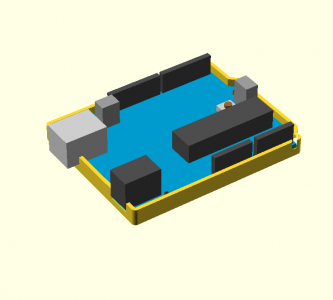
Addendum: I found a model for an Arduino in OpenSCAD, and tried merging it with my bumper. That revealed that I had made a mistake in the code listed above: the DC connector should be 350 mils wide: the slot as coded would be too narrow. I also decided to widen the relief channels for the pins which stick out the bottom, and provide an extra depth relief to support the DC and USB jacks. When I get a chance to print this out, I’ll probably upload the kit-n-kaboodle to thingiverse once I’m happy with it.

Until then, here’s the tease:

witharduino

Addendum2: I experimented a bit with export options. I projected the bumper down to 2D, exported it as DXF, and then imported it into Inkscape, where I could convert it to a 300dpi bitmap. Voila.

path3391

PIR sensor from TAUTIC.COM

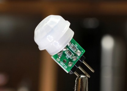
pirA few days ago, I heard that Jayson Tautic (@tautic), manufacturer and purveyor of a interesting electronic prototyping goodies, had put up an interesting offering: a small PIR (passive infra red) motion detector. I’m always up for a new sensor to play with, so I ordered a pair for fun, and they arrived on Friday.

It’s a cute little package, much smaller than I expected, about 8x10mm. It has three pins, but didn’t come with a datasheet. Some queries among my buddies on the #tymkrs channel on afternet turned up this datasheet which appears to be the part. That was good enough to sort out the pinouts: the pin labeled + is the supply voltage, the pin on the opposite side is ground, and the middle pin is the sense pin. When the sensor detects motion, that pin goes high, and remains so for two seconds after the motion halts. And that’s about it.

It was tremendously simple to wire it up to an Arduino for testing. I wired the sense pin to pin 8, and then used this simple sketch…

[sourcecode lang=”cpp”]
const int pin = 8 ;
const int ledPin = 13 ;

void
setup()
{
Serial.begin(9600) ;
pinMode(pin, INPUT) ;
pinMode(ledPin, OUTPUT) ;
}

void
loop()
{
Serial.println("NO MOTION DETECTED") ;
digitalWrite(ledPin, LOW) ;
while (digitalRead(pin) == LOW)
delay(100) ;
digitalWrite(ledPin, HIGH) ;
Serial.println("MOTION DETECTED") ;
while (digitalRead(pin) == HIGH)
delay(100) ;
}
[/sourcecode]

It will turn on the LED wired to pin 13 when motion is detected, and also prints a message to the serial port. Simple.

I haven’t done any testing with this, but it appears they might be sensitive enough to detect the motion of my cat, which seems like it could be interesting. Stay tuned.

Some small experiments with Arduino sound…

Last year, I spent a little bit of time to create a set of blinking Christmas lights that I could mount in a hat. It was powered by an ATtiny13 and mounted in an Altoids tin. While setting up my Christmas tree last weekend, I found them, and they still work. In case you missed it, here are some of the videos I did at the time:


It was kind of fun, and still works, so I’ll probably be wearing it around. But I thought to myself: what could I do to make it better?

The obvious thing to me was to try to add more lights, more patterns, and music. Rather than use a naked ATtiny13, I thought that I would just go ahead and use an Arduino. I have an Arduino Mini that I got to use in a radio beacon experiment that I haven’t gotten to yet, so that seemed like a good idea. The question was then: what could I do?

I came up with these ideas:

  • More lights. At $.99 a string, I could put a lot more light strands in place. That would make fancier “chase” effects possible, and generally just look cool.
  • More effects.
  • A better hat! The missus has a new sewing machine, and could probably use a new project. I have a big head, so finding a Santa cap that fits is always a bit of a chore, and if we made our own, we could add pockets for batteries and sew in the wiring to make it neater.
  • Sound. It would be cool to add a small speaker and amplifier, and play music with synchronized light effects.

I don’t think any of this is especially hard. The only part I hadn’t really done before (other than the sewing bit) was sound. So, last night I started reviewing what libraries existed for sound on the Arduino. I actually have a WAV shield lying around, but I was looking for something a bit more minimal: I didn’t really care to use a full shield, both for size and for just a sense of minimality. I kind of wanted to store a few Christmas tunes in the on-chip flash, and then synthesize some high quality (well, decent quality) audio directly.

Which lead me to the Mozzi sound framework.

The Mozzi sound framework for Arduino

Mozzi seems to generate some pretty cool sounds (samples here) and is a pretty neat framework. I decided to give it a whirl last night. I was somewhat delayed by trying to get the Arduino software installed on my new Windows 8 laptop. Apparently the drivers that you need aren’t sufficiently digitally signed for Microsoft to trust them, and you have to go to some effort to disable those checks and get them to install. But once I got that sorted out, I didn’t have any problem downloading and playing with the Mozzi library. To hear the samples, I just hooked a high impedance earphone from a crystal radio to pin 9 and ground, and they worked as expected. The Mozzi webpage actually recommends a bit of output filtering: they have a 6Khz lowpass filter followed by a 16Khz notch filter to get rid of the PWM noise. The design is quite simple RC filter and uses very common values of components, so it should be pretty easy to build. I spent a few minutes entering the schematic into LTSpice, and it seems like it works as expected, and should help audio quality considerably.

Going forward, I need to find some decent Christmas tunes (perhaps in ABC notation like these, although I’d like more complex, polyphonic tunes) and figure out how to synthesize some nice sounds in the incredibly limited time available, as well as control the switching of the LEDs themselves. Stay tuned for more experiments.

ArduinoSudoku – sudoku on arduino

Just a quickie Arduino project that I ran across this morning: Sudoku on the Arduino. It’s pretty cute, since it uses the Arduino tvout library to generate video, meaning that you can display and play on your TV set. Neat! The only real description of the project is inside the zip file which you can find on the following Google Project host, but it’s pretty good at describing both the theory and implementation. I haven’t downloaded and tried it myself yet, but maybe this weekend.

SudokuUsingTVout.zip – mysudoku – ArduinoSudoku – sudoku on arduino – Google Project Hosting