Category Archives: electronics

Arduino + DS1307 Real Time Clock

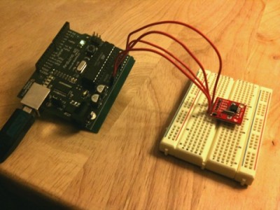
Okay, this is no big deal: lots of people have done it before. But while I was watching TV, I soldered some header pins to the DS1307 based real time clock board I got from sparkfun.com , and coded up this simple program to read the time from it. I’d never really used the Wire library, but it’s pretty straightforward. I plugged the board into a breadboard, jumpered it into the Arduino, and with a bit of tweaking, it works.

[sourcecode lang=”C”]

#include <Wire.h>
#define DS1307_I2C_ADDRESS (0x68)

byte h, htmp, m, s ;
byte dow, dom ;
byte mn, yr ;

byte
BCDToDEC(byte val)
{
return (val >> 4) * 10 + (val & 0xf) ;
}

void
doDate()
{
Wire.beginTransmission(DS1307_I2C_ADDRESS) ;
Wire.send(0x0) ;
Wire.endTransmission() ;

Wire.requestFrom(DS1307_I2C_ADDRESS, 7) ;

s = BCDToDEC(Wire.receive() & 0x7f) ;
m = BCDToDEC(Wire.receive()) ;
htmp = Wire.receive() ;
dow = BCDToDEC(Wire.receive()) ;
dom = BCDToDEC(Wire.receive()) ;
mn = BCDToDEC(Wire.receive()) ;
yr = BCDToDEC(Wire.receive()) ;

if (htmp & (1<<6)) {
/* 12 hour mode… */
h = BCDToDEC(htmp&0x1F) ;
} else {
/* 24 hour mode… */
h = BCDToDEC(htmp&0x3F) ;
}

if (h < 10) Serial.print("0") ;
Serial.print(h, DEC) ;

Serial.print(":") ;
if (m < 10)
Serial.print("0") ;
Serial.print(m, DEC) ;
Serial.print(":") ;
if (s < 10)
Serial.print("0") ;
Serial.print(s, DEC) ;

if (htmp & (1<<6)) {
if (htmp & (1<<5))
Serial.print("PM") ;
else
Serial.print("AM") ;
}
Serial.print(" ") ;

Serial.print(mn, DEC) ;
Serial.print("/") ;
Serial.print(dom, DEC) ;
Serial.print("/") ;
Serial.print(yr, DEC) ;
Serial.print("\n") ;
}

void
setup()
{
Wire.begin() ;
Serial.begin(9600) ;
}

void
loop()
{
doDate() ;
delay(1000) ;
}
[/sourcecode]

Nothing earth shattering here. Eventually, I want my beacon controller to have a real time clock, and this seemed like a good way to go. Having a reasonably accurate real time clock means that I can make my beacon send WSPR messages, which start at the beginning of even numbered minutes on the hour. Baby steps.

PCB Order via DorkbotPDX

A while ago, I remember hearing that DorkbotPDX had some deal where you could submit PCB designs and have them ganged with other designs and manufactured for a pittance (or at least, a small number of pittances) but I hadn’t bothered to chase down the details. Recently, I’ve thought of making a small board with an Atmel AVR, a RTC and maybe a DTC to use in (among other things) my beacon controller so I looked it up. Pretty neat: three copies of any board you submit with a cost of $5 per square inch. Thus, if you have a 2″x1″ board, you get three copies for $10. They can also do 4 layer boards for $10 a square inch. Nifty.

PCB Order | DorkbotPDX.

Your first Digital to Analog Converter

To control my simple Beacon, I used PWM and as simple (but slow) RC filter. That worked good enough for a test, but I really wanted the voltage changes to be more rapid. What alternatives are there? Well, I actually ordered a $5 I2C DAC board from Sparkfun, but it hasn’t arrived. The obvious low-tech alternative is to use a R-2R resistor ladder. Somewhat coincidently, hackaday had a tutorial on them just a few days ago.

Your first Digital to Analog Converter build – Hack a Day.

Addendum: This page talks about the need for a buffer amplifier to be used in concert with the D/A converter. That’s because any load (resistance) you place on the output works in concert with the resistor network to change the output voltage. If that load varies, it will also cause your output voltage. By buffering through a buffer amplifier (in this case, a rather cheap op amp) you prevent all that, and the DAC works more reliably.

Simulating a 40m bandpass filter in LTSpice

A few days ago, I created a small program to compute bandpass filters using the equations from Experimental Methods in RF Design. Basically, you can pick a given inductor value, and then it solves for all the necessary capacitors. What wasn’t immediately obvious from the equations and the values that are generated was how these values interacted to alter the shape of the filter, and how variations in their value (perhaps to match easy to find capacitors) could change the frequency response.

So, I decided to go ahead and play with it using LTSpice.

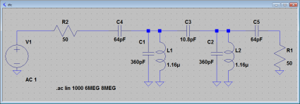
Here’s an example filter that I got by specifying a 7.1Mhz center frequency, with a 250khz bandwidth. The source and load impedance are both specified to be 50 ohms. Using the program that I posted before, I got the following component values:

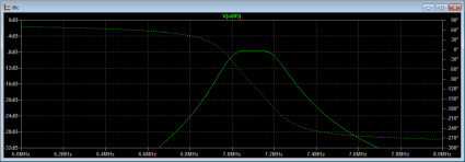
I then could go ahead and simulate the filter using LTSpice’s AC analysis, which yielded the following frequency response:

It looks pretty good. Using LTSpice, it’s pretty easy to check how (for instance) variations in the source or load impedance change the shape of the filter, or how small variations in the value of components affect the losses.

One thing that I didn’t immediately figure out was how to employ the inductor Q. LTSpice doesn’t include a place to enter Q, but it’s easy to compute the necessary parallel resistance (it’s just 2.0 * pi * F * L * Q) which LTSpice can use.

I really need to build one of these for the DC40B.

Batsocks – Text on TV – Introduction

The chaps over at the Batsocks blog sell a cute little gadget called the “Tellymate”: a nice little serial->video converter that is very, very simple. It uses a single Atmel AVR Mega, and handful of other extra components to implement a full character mapped 38×25 character display terminal which reads characters from a serial input port. But what’s really great is that they have all sorts of good information on how the gadget actually works, meaning that you can adapt the techniques and ideas for your own use. Very cool.

Batsocks – Text on TV – Introduction.

The interesting bit that the Tellymate implements is a higher density display than can be achieved with the arduino TV-out library that I mentioned a few days ago. It does this by leveraging the SPI output to automatically clock out bits 9 at a time, which gives you enough time to actually stream out 38 characters (about double what I can achieve with the Arduino library). Very neat, but there are some details which are a bit crufty. Lots of good information.

Simulating a (simplified) Ring Oscillator

Okay, simulating the analog parts of the actual physical ring oscillator last night made me ask some questions, so I thought it might be useful to try a very simple discrete simulation. If you looked at the schematic I posted yesterday, you’ll note that the ring is really just made up of single transistor inverters. The capacitors in combination with the resistors implement a delay line. So, that’s what I decided to code up: a ring of simple inverters, each with a “gate delay” of values which are very close to 1 second. Whenever the input to the inverter is scheduled, the output is swapped to its negation at the time in the future plus its gate delay, which resets the clock of the next gate, and so on. I normally would use a priority queue and the like to keep track of which gate should fire next, but for as few stages as I’m likely to implement, I frankly just search for the gate with the lowest time by linear search, and then proceed. To make the “simulation” a tiny bit more interesting, I print the values of the gates in “pseudo-real” time (I spend it up by a factor of 10). Here’s the code.

[sourcecode lang=”C”]
#include <stdio.h>
#include <stdlib.h>
#include <unistd.h>

#define N 79

unsigned char val[N] ;
double delay[N] ;
double clock[N] ;

#define BIG 1e6

main()
{
int i, idx ;
double t = 0., soonest ;

for (i=0; i<N; i++) {
val[i] = 0 ;
delay[i] = clock[i] = 1.0 + drand48() * 0.01 – 0.005 ;
}

for (;;) {
/* find the inverter that will trip soonest */
idx = 0 ;
soonest = clock[idx] ;

for (i=1; i<N; i++)
if (clock[i] < soonest) {
soonest = clock[i] ;
idx = i ;
}

/* subtract the clock from all the inputs */

for (i=0; i<N; i++)
clock[i] -= soonest ;

t += soonest ;

val[(idx+1)%N] = 1-val[idx] ;
clock[(idx+1)%N] = delay[(idx+1)%N] ;
clock[idx] = BIG ;

usleep(soonest * 1000000. / 10.) ;
for (i=0; i<N; i++)
putchar("_X"[val[i]]) ;
printf("\r") ;
fflush(stdout) ;

}
}
[/sourcecode]

It’s pretty interesting to watch (at least to me). I’ll have more to comment tonight.

Ring Oscillator Das Blinkenlights

Crap, the original entry I made for this got screwed up somehow. Oh well.

Alan, VK2ZAY, was experimenting with ring oscillators, which make some very nice blinking light displays indeed.

YouTube – Ring Oscillator Das Blinkenlights


Before this post got mangled, I was experimenting with putting the circuit into LTSpice and analyzing it. My brain was too enfeebled to figure out the relationship that governed the selection of the values for the bias and current limiting resistors and the capacitors, so I figured I’d just code it up. Of course, now that this post is mangled, I’ll have to redo the LTSpice analysis, but what I discovered was that under some conditions, LTSpice predicted very long start times for the ring oscillator, or it simply failed to initialize. This is because I typed exactly the same value for the components. If I varied the value of the components by just 0.1%, the oscillator had no problem firing up.

I’ll redo the schematic and the graphs tomorrow. Stay tuned.

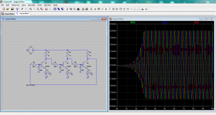
Addendum: Couldn’t wait. Redid the simulation using the values that Alan thoughtfully provided on twitter. Here’s the screen dump: commentary to follow at a later date.

LTSpice simulation of a ring oscillator

LatticeXP2 Brevia Development Kit, with a deal breaker

I’ve been playing with a BASYS2 FPGA development kit from digilentinc.com, and pondering the world of digital system design. I chose the BASYS2 because of its low price ($70) and because it included a reasonable number of LEDs, switches, a VGA interface and a connector for a PS/2 keyboard. Still, I’ve been looking for other small, reasonably priced FPGA kits, perhaps even ones which aren’t based on the Xilinx chips. Today I learned of a nice looking little $49 kit from Lattice:

LatticeXP2 Brevia Development Kit.

While it doesn’t include the VGA or PS/2 interfaces, it does include a 1Mbit static ram on board, which perhaps makes it more interesting for experimenting with FPGA cpus. But here’s the thing: it includes a parallel port programming cable, and literally no computers I currently use have a parallel port anymore. They tel you that you need a special USB cable: the HW-USBN-2A which is not included. Oh well, think I, that can’t be too bad…

That cable costs $149.

Yes, the programming cable for this FPGA board is 3x the cost of the entire board.

Deal, broken.

Design of a simple ALU…

A couple of weeks ago, I noticed a bunch of links to a 16 bit ALU designed to operate using blocks which are defined in the game Minecraft. It got me thinking, and ordered the book that inspired that work. It contains the specification for an ALU which is very simple, and yet surprisingly powerful ALU (at least, considering the number of gates that it would take to implement it).

Here’s a C function that implements the ALU. I went ahead and just used the integer type, rather than the 16 bits specified in the Hack computer, but it doesn’t really matter what the word size is.

[sourcecode lang=”C”]
#define ZERO_X (1<<0)
#define COMP_X (1<<1)
#define ZERO_Y (1<<2)
#define COMP_Y (1<<3)
#define OP_ADD (1<<4)
#define COMP_O (1<<5)

unsigned int
alu(unsigned int x, unsigned int y, int flags)
{
unsigned int o ;

if (flags & ZERO_X) x = 0 ;
if (flags & ZERO_Y) y = 0 ;
if (flags & COMP_X) x = ~x ;
if (flags & COMP_Y) y = ~y ;
if (flags & OP_ADD)
o = x + y ;
else
o = x & y ;
if (flags & COMP_O) o = ~o ;
return o ;
}
[/sourcecode]

The function takes in two operands (x and y) and a series of six bit flags. The ZERO_X and ZERO_Y say that the X input and Z input should be set to zero. The COMP_X, COMP_Y, and COMP_O flags say that the X, Y, and output values should be bitwise negated (all the zeros become ones, and the ones zeros). The OP_ADD flag chooses one of two functions: when set, it means that the two operands should be added, otherwise, the two operands are combined with bitwise AND.

There are a surprisingly large number of interesting functions that can be calculated from this simple ALU. Well, perhaps not surprising to the hardware engineers out there, but I’ve never really thought about it. It’s obvious that you can compute functions like AND and ADD. Let’s write some defines:

[sourcecode lang=”C”]
#define AND(x,y) alu(x, y, 0)
#define ADD(x,y) alu(x, y, OP_ADD)
[/sourcecode]

You can also compute functions like OR using DeMorgan’s Law: OR(x,y) = ~(~X AND ~Y).

[sourcecode lang=”C”]
#define OR(x,y) alu(x, y, COMP_X|COMP_Y|COMP_O)
[/sourcecode]

You can make some constants such as zero and one. Zero is particularly easy, but one requires an interesting trick using twos-complement arithmetic.

[sourcecode lang=”C”]
#define ZERO(x,y) alu(x, y, ZERO_X|ZERO_Y|OP_ADD)
#define ONE(x,y) alu(x, y, ZERO_X|COMP_X|ZERO_Y|COMP_Y|OP_ADD|COMP_O)
[/sourcecode]

To make sense of the definition of ONE, you need to know that in twos-complement arithmetic, -x = ~x + 1, or in other words, -x – 1 = ~x. Look at the definition of ONE, it computes ~(~0 + ~0). After the addition, the register contains all 1s, except for the low order bit. Negating that builds a one. You can also build a -1, or even a -2.

You can also obviously get either operand, or their logical complements. There are even multiple implementations:

[sourcecode lang=”C”]
#define NOTX(x,y) alu(x, y, COMP_X|ZERO_Y|COMP_Y)
#define NOTX(x,y) alu(x, y, COMP_X|ZERO_Y|OP_ADD)
#define NOTX(x,y) alu(x, y, ZERO_Y|COMP_Y|COMP_O)
#define NOTX(x,y) alu(x, y, ZERO_Y|OP_ADD|COMP_O)
[/sourcecode]

We saw how we could add, we could also construct a subtractor:

[sourcecode lang=”C”]
#define SUB(x,y) alu(x, y, COMP_X|OP_ADD|COMP_O)
[/sourcecode]

We saw how we could compute +1 and -1, but we can also add these constants to X or Y..

[sourcecode lang=”C”]
#define DECY(x,y) alu(x, y, ZERO_X|COMP_X|OP_ADD)
#define DECX(x,y) alu(x, y, ZERO_Y|COMP_Y|OP_ADD)
#define INCY(x,y) alu(x, y, ZERO_X|COMP_X|COMP_Y|OP_ADD|COMP_O)
#define INCX(x,y) alu(x, y, COMP_X|ZERO_Y|COMP_Y|OP_ADD|COMP_O)
[/sourcecode]

I thought it was pretty neat or such a small implementation. The hardest part to implement is the adder, all the rest is a pretty trivial number of gates. If you use a simple ripple adder, even the adder is pretty small.

Addendum: Here’s a more (but not entirely) exhaustive list of functions that are implemented.

[sourcecode lang=”C”]
#define ADD(x,y) alu(x, y, OP_ADD)
#define AND(x,y) alu(x, y, 0)
#define DECX(x,y) alu(x, y, ZERO_Y|COMP_Y|OP_ADD)
#define DECY(x,y) alu(x, y, ZERO_X|COMP_X|OP_ADD)
#define INCX(x,y) alu(x, y, COMP_X|ZERO_Y|COMP_Y|OP_ADD|COMP_O)
#define INCY(x,y) alu(x, y, ZERO_X|COMP_X|COMP_Y|OP_ADD|COMP_O)
#define MINUS1(x,y) alu(x, y, COMP_X|ZERO_Y|COMP_O)
#define MINUS1(x,y) alu(x, y, ZERO_X|COMP_O)
#define MINUS1(x,y) alu(x, y, ZERO_X|COMP_X|ZERO_Y|COMP_O)
#define MINUS1(x,y) alu(x, y, ZERO_X|COMP_X|ZERO_Y|COMP_Y)
#define MINUS1(x,y) alu(x, y, ZERO_X|COMP_X|ZERO_Y|OP_ADD)
#define MINUS1(x,y) alu(x, y, ZERO_X|COMP_Y|COMP_O)
#define MINUS1(x,y) alu(x, y, ZERO_X|ZERO_Y|COMP_O)
#define MINUS1(x,y) alu(x, y, ZERO_X|ZERO_Y|COMP_Y|COMP_O)
#define MINUS1(x,y) alu(x, y, ZERO_X|ZERO_Y|COMP_Y|OP_ADD)
#define MINUS1(x,y) alu(x, y, ZERO_X|ZERO_Y|OP_ADD|COMP_O)
#define MINUS1(x,y) alu(x, y, ZERO_Y|COMP_O)
#define MINUS2(x,y) alu(x, y, ZERO_X|COMP_X|ZERO_Y|COMP_Y|OP_ADD)
#define NAND(x,y) alu(x, y, COMP_O)
#define NOR(x,y) alu(x, y, COMP_X|COMP_Y)
#define NOTX(x,y) alu(x, y, COMP_X|ZERO_Y|COMP_Y)
#define NOTX(x,y) alu(x, y, COMP_X|ZERO_Y|OP_ADD)
#define NOTX(x,y) alu(x, y, ZERO_Y|COMP_Y|COMP_O)
#define NOTX(x,y) alu(x, y, ZERO_Y|OP_ADD|COMP_O)
#define NOTY(x,y) alu(x, y, ZERO_X|COMP_X|COMP_O)
#define NOTY(x,y) alu(x, y, ZERO_X|COMP_X|COMP_Y)
#define NOTY(x,y) alu(x, y, ZERO_X|COMP_Y|OP_ADD)
#define NOTY(x,y) alu(x, y, ZERO_X|OP_ADD|COMP_O)
#define ONE(x,y) alu(x, y, ZERO_X|COMP_X|ZERO_Y|COMP_Y|OP_ADD|COMP_O)
#define OR(x,y) alu(x, y, COMP_X|COMP_Y|COMP_O)
#define RSUB(x,y) alu(x, y, COMP_Y|OP_ADD|COMP_O)
#define SUB(x,y) alu(x, y, COMP_X|OP_ADD|COMP_O)
#define X(x,y) alu(x, y, COMP_X|ZERO_Y|COMP_Y|COMP_O)
#define X(x,y) alu(x, y, COMP_X|ZERO_Y|OP_ADD|COMP_O)
#define X(x,y) alu(x, y, ZERO_Y|COMP_Y)
#define X(x,y) alu(x, y, ZERO_Y|OP_ADD)
#define XANDNOTY(x,y) alu(x, y, COMP_Y)
#define XORNOTY(x,y) alu(x, y, COMP_X|COMP_O)
#define Y(x,y) alu(x, y, ZERO_X|COMP_X)
#define Y(x,y) alu(x, y, ZERO_X|COMP_X|COMP_Y|COMP_O)
#define Y(x,y) alu(x, y, ZERO_X|COMP_Y|OP_ADD|COMP_O)
#define Y(x,y) alu(x, y, ZERO_X|OP_ADD)
#define YANDNOTX(x,y) alu(x, y, COMP_X)
#define YORNOTX(x,y) alu(x, y, COMP_Y|COMP_O)
#define ZERO(x,y) alu(x, y, COMP_X|ZERO_Y)
#define ZERO(x,y) alu(x, y, ZERO_X)
#define ZERO(x,y) alu(x, y, ZERO_X|COMP_X|ZERO_Y)
#define ZERO(x,y) alu(x, y, ZERO_X|COMP_X|ZERO_Y|COMP_Y|COMP_O)
#define ZERO(x,y) alu(x, y, ZERO_X|COMP_X|ZERO_Y|OP_ADD|COMP_O)
#define ZERO(x,y) alu(x, y, ZERO_X|COMP_Y)
#define ZERO(x,y) alu(x, y, ZERO_X|ZERO_Y)
#define ZERO(x,y) alu(x, y, ZERO_X|ZERO_Y|COMP_Y)
#define ZERO(x,y) alu(x, y, ZERO_X|ZERO_Y|COMP_Y|OP_ADD|COMP_O)
#define ZERO(x,y) alu(x, y, ZERO_X|ZERO_Y|OP_ADD)
#define ZERO(x,y) alu(x, y, ZERO_Y)
[/sourcecode]
Making a soft-circuit input device for your computer

I’m intrigued by various uses for embedded processors, and so are my readers. I hadn’t seen this particular microcontroller board before, the “Teensy”, which is very similar to the Arduino, except that it is uses an ATMEL AVR chip with a direct support for USB. The link also points at a nifty interface to “soft circuit” elements, which probably has some nifty controller applications.

Make: Online : Making a soft-circuit input device for your computer.

RBox: A diy 32 bit game console for the price of a latte – rossum’s posterous

32 bit processors now cost $1. That means that you can build fairly competent video games for the price of a coffee. Check it out:

RBox: A diy 32 bit game console for the price of a latte – rossum’s posterous.

Addendum: The prototype is actually built on a small board that can be ordered from Digikey for about $30. The software is a teensy bit clever (maybe more than a teensy bit). It generates video entirely via interrupts, but the clever thing is that it uses the SPI interface on the chip in a way that allows you to generate the necessary chroma signals without overburdening the main cpu, which generates the luma part of the signal. Quite clever.