The “official” ESP8266 Wiki…

April 4, 2015 | Development Boards, Embedded, My Projects | By: Mark VandeWettering

This morning I’m still drinking coffee and waking up, but I was pointed at “the ESP8266 wiki”, which appears to be this Wiki page. Bookmarked mostly so I can quickly find it again. But it has some good information. If I haven’t teased you enough with this experimentation, consider these features of the ESP8266:

  • It’s a wireless SoC
  • It has GPIO, I2C, ADC, SPI, PWM and some more
  • It’s running at 80MHz
  • 64KBytes of instruction RAM
  • 96KBytes of data RAM
  • 64KBytes boot ROM
  • It has a Winbond W25Q40BVNIG SPI flash
  • It’s a RISC architecture
  • The core is a 106micro Diamond Standard core (LX3) made by Tensilica
  • The ESP8266 chip is made by Espressif
  • Modules bearing this chip are made by various manufacturers

And most importantly, you can get modules starting for as low as $3. You can get modules with the same chipset, more pins and USB for just $8.70 (plus shipping) (thanks MicroHex for suggesting it). And now, with the ability to program them from the Arduino environment? I’m definitely going to be experimenting with them.

More ESP8266 Experimentation: Giving it the Boot…

April 4, 2015 | Arduino, Hacking, LED, My Projects | By: Mark VandeWettering

Got a chance to play around a bit more with the ESP8266 tonight. I dug out a nice little dual output power supply board that I had got from tautic.com with the hope that it would eliminate some of the erratic behavior that I had observed before. Sadly, that didn’t seem to solve my problem. Luckily, after a bit of googling, I think I see what’s going on.

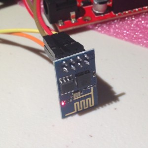
First of all, the ESP-01 module I have is really limited in its number of pins. There are only a total of 8 pins brought on onto the header. They are:

ESP8266_pinout

  • UXTD — connects to the UART 0 transmit pin
  • CH_PD — must be tied high (to 3.3v) to boot
  • RST — pull low to reset
  • VCC — connect to 3.3V power supply
  • GND
  • GPIO2 — general purpose IO pin (but see below)
  • GPIO0 — general purpose IO pin (but see below)
  • URXD — connects to UART 0 receive pin

I had read that in order to flash, you needed to set GPIO0 low (tie it to ground) but for normal operation, you could either pull it high, or simply let it float. That seemed to work fine. Then, I tried to use GPIO2 to power a small led. It would work fine if I hooked it up after booting, but if I was wired up both the red and blue leds would come on, and it would not boot properly. It turns out that GPIO2 must be left high or floating for normal operation to occur.

This article explains some of the issues. It appears that a 2.2k pull up resistor will probably do the trick. It’s too late tonight for me to scramble around, but I’ll try it tomorrow.

A few more snaps of hummingbirds…

April 3, 2015 | My Projects | By: Mark VandeWettering

A couple more quick snaps from my hummingbird camera. I’m going to try to work on some improvements over the weekend, but shockingly we are gonna get some rain, so I may concentrate on getting it waterproofed and ready for life outdoors.

birds

In brain related news…

April 3, 2015 | Mad Science, Science | By: Mark VandeWettering

Carl Zimmer tweeted this ad for the USC Mark and Mary Stevens Neuroimaging and Informatics Institute:


brane

I’d ask for a second opinion.

Not all is easy-peasy with the ESP8266, with a short addendum

April 3, 2015 | Arduino, Development Boards, Embedded | By: Mark VandeWettering

Okay, after I did my quick video record yesterday re: the ESP8266, I continued to play with it a bit more. And, it must be said, I had a little bit of difficulty which I thought I would write up so that other people who are experiencing the same issues might be able to comment, and hopefully benefit as we get the problem resolved.

First of all, I observed a couple of different issues in just repeatedly playing with the board. Occasionally, the board would seemingly hang when a new URL request was received. It would print out an informational message that said that a new client had connected, but it wouldn’t actually print the message that it received. I had to recycle the power to reset it.

Secondly, when I had the LED connected, it would sometimes just fail to boot my program entirely. It would spew random crud into the serial monitor. Not good.

I suspect that both of these things might have to do with inadequate power supply. I am powering it entirely from a little 3.3v FTDI cable I had lying around (I believe it is this one, now retired.) If I read the datasheet properly, it appears that it can only power about 50ma of external circuitry. That’s simply not enough: I’m kind of shocked that it can boot at all. Peak current draw is probably somewhere around 300ma. Most every page on ESP8266 development says that I should use a high quality 3.3v power supply able to supply at least 500ma.

Next experiments will try to feature a better power supply. MOAR POWER.

Addendum: The module that I am using is the ESP-01. As you can see, it’s very simple, has only 8 pins, and is not breadboard friendly. Luckily for experimenters, there are other varieties of boards available based upon the same chipset. For instance, the ESP-04 has seven GPIO pins broken out, and can needs an external antenna. The ESP-201 is much more breadboard friendly, and includes both an on-board antenna, and UFL connector for an external antenna. There are lots of other types too, all very reasonably priced. If you haven’t bought the ESP-01 already, some of these other boards might be better to experiment with. But there are also people making various adapters for the ESP-01, such as the ESP8266 buddy, which sells for a paltry $2.50 and can adapt the ESP-01 to your breadboard. I think I’ll be getting a few of these.

First electrons for the ESP8266…

April 2, 2015 | Arduino, Development Boards, Embedded, Internet of Things, My Projects | By: Mark VandeWettering

IMG_5702In the telescope making world, we call the first time that a telescope is used to look at the sky “first light”. I’ve decided to call the first time I load some code onto a new development board “first electrons”.

A few weeks ago, when I did a video that illustrated some of the bucket of development boards that I had lying around, I decided that I should at least make a sincere effort to try to do something, anything, with each of them. Since then, I’ve discovered platformio which has enabled me to at least get some code running on the more obscure ARM based boards that I had lying around. Buoyed by that positive experience, I sought to see how I could get code running on some of the other boards. Tonight’s board was the ESP8266, a little cheap board (I paid $6 or so for mine, I’ve seen them on eBay for as little as $3) which are often used as serial-Wifi links, but which actually include a nifty little 32 bit SOC.

Luckily, the gods have smiled in the form of a three part article (Part 1 Part 2 Part 3) by Alasdair Allen for Make magazine. Previously, getting code to compile onto the ESP8266 required finding the right version of gcc and the download esptool, configuring it… Who has the time? What’s awesome is that now you can download a version of the Arduino environment that already has the necessary compiler and tools installed, and use the friendly, comfortable Arduino environment to compile and run code.

So, tonight, that’s what I did!

Conveniently, I had an 3.3V FTDI serial cable that I had purchased back when I was experimenting with 3.3V boards. That’s convenient, because otherwise I’d have to wire up a 3.3V voltage regulator, which isn’t hard, but at least takes one more step. Using the diagram in Part 2 of the article listed above, I setup some jumper wires to connect it all up. I then downloaded the necessary version of the Arduino environment (for my Linux laptop), installed it, loaded the WifiServer example application, modified it with my own network’s SSID and password, and tried compilation. It compiled fine, but when I tried to download the new code to the ESP8266, I got a communication error. I double checked all the connections against the diagram, no dice. Hmmph. There was one small bit of confusion that I always have when hooking up serial devices: the RX (receive) pin of one side needs to be connected to the TX (transmit) on the other, and vice versa. But when you try to document this, it can be confusing: if an end of your cable is labelled RX, does it mean that you should attach it to the RX? Or that the other end of the cable is RX, so you should connect it to TX?

I swapped RX and TX. And voila. The download works just fine.

To reboot and run the code, you need to remove one of the ground connections from the boad and cycle the power. I then fired up the serial monitor, changed the baud rate to 115200, and then watched it boot. It printed out that it was attempting to connect to my network, printed a series of periods, and eventually reported it’s IP address.

Nifty! I need to go dig up some current limiting resistors (maybe 220 ohms or so) so I can test it, but I verified that if I accessed http://192.168.1.116/gpio/0, it turns the gpio pin low, and http://192.168.1.116/gpio sends it high. Voila!

Well, with a few caveats. It seemed a little unreliable, and seemed to hang a couple of times. I’m not sure what the deal is. I’m suspicious about how much power my FTDI cable can actually supply, maybe that’s part of it. Or it could be software related. I’ll have to play with it more to be sure. But it’s pretty nifty. I’m sure I’ll be playing with it more. Good stuff.

Addendum: I dug up an LED and a 330 ohm current limiting resistor, and then recorded this trivial little demonstration.


More on Arduino v. Arduino…

April 2, 2015 | Arduino | By: Mark VandeWettering

Make just published this interview with Arduino founder Massimo Banzi about the internal schism that’s currently embroiling the Arduino community.

It is true that this represents only one side of the story, but it does seem that at a minimum, Arduino SRL (represented at http://arduino.org) has copied much of the Arduino LLC website without credit to the other creators. Whether that rises to the level of illegality, IMO it is, pardon my language, a dick move. The story spun on the arduino.org website here does not strike me as answering any of the criticisms, and has the general feel of dodging important questions.

Have any of the major Arduino distributors like SparkFun or Adafruit made any mention of how this internal spat is affecting their deals and supply chains?

Another hummingbird shows up on the camera…

April 1, 2015 | My Photos, My Projects, Raspberry Pi | By: Mark VandeWettering

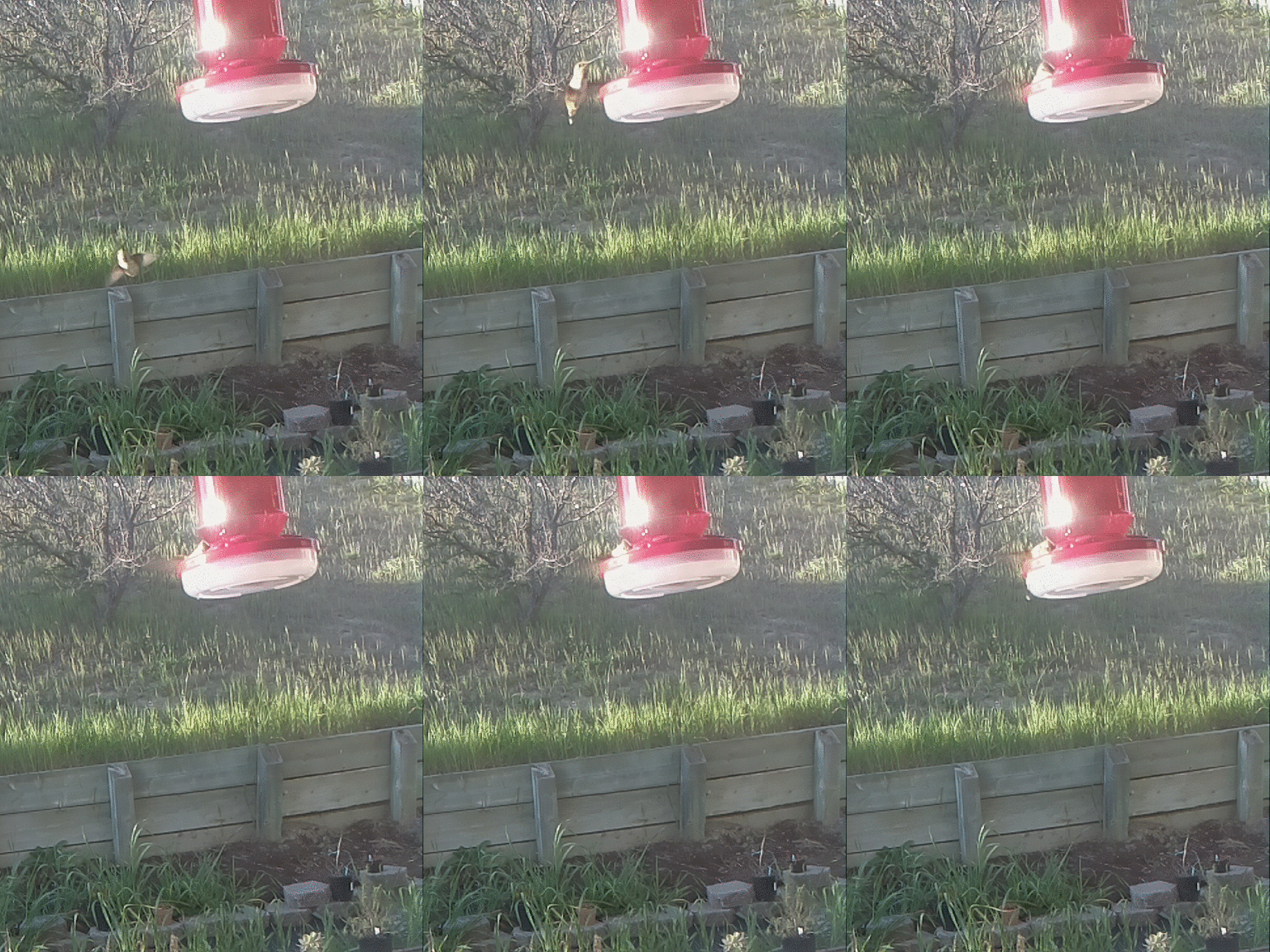
When I got home today, it appeared that I had a few more images from my hummingbird cam. Luckily, I got several nice frames of him her (probably), so I put them together into an animated GIF. Nifty. When I get a chance to do more stuff on it this weekend, I hope to get even better recordings, and setup the camera closer. Till then, it’s been a fun project.

Hummingbird

Addendum: I converted the individual JPEG images into an animated GIF using the ImageMagick toolkit on Linux. The command was:

convert -crop 512x576+512x576 +repage -loop 0 -delay 200 frames.*.jpg loop.gif

The -delay value probably could have been shrunk a bit. I used the -crop option to just select the right half of the screen. When you post animated gifs in WordPress, you need to post them at full size, the shrunken versions won’t animate.

Arduino? Perhaps we need OurDuino…

March 31, 2015 | Arduino | By: Mark VandeWettering

It’s no secret that I’ve been a fan of the Arduino. More than any other board, it’s got me into hacking little bits of hardware and programming in the small, and has been part of numerous projects that I’ve tinkered together, and others that I’ve helped mentor young people with. It’s a cute platform for a number of reasons:

  • They are widely available.
  • They are reasonably (well, sort of, more on this later) priced.
  • They are supported on all major platforms: Linux, Mac OS X and Windows
  • Their programming environment is a single, simple download.
  • Their programming libraries allow people to get started quickly.
  • There are a fair number of good shields to do hardware expansion.
  • And perhaps most importantly, they have a large community of people who develop and share code and techniques.

By my estimation, no other platform has this set of features.

Sadly, it appears that there is trouble in paradise. From this article on Hackaday:

Arduino LLC is the company founded by [Massimo Banzi], [David Cuartielles], [David Mellis], [Tom Igoe] and [Gianluca Martino] in 2009 and is the owner of the Arduino trademark and gave us the designs, software, and community support that’s gotten the Arduino where it is. The boards were manufactured by a spinoff company, Smart Projects Srl, founded by the same [Gianluca Martino]. So far, so good.

Things got ugly in November when [Martino] and new CEO [Federico Musto] renamed Smart Projects to Arduino Srl and registered arduino.org (which is arguably a better domain name than the old arduino.cc). Whether or not this is a trademark infringement is waiting to be heard in the Massachussetts District Court.

According to this Italian Wired article, the cause of the split is that [Banzi] and the other three wanted to internationalize the brand and license production to other firms freely, while [Martino] and [Musto] at the company formerly known as Smart Projects want to list on the stock market and keep all production strictly in the Italian factory.

Yikes.

I tend to side with Massimo for two reasons: one is, I’ve met Massimo at the San Mateo Maker Fair, and he was a nice, friendly, interesting guy. Second is that I think the value of the Arduino platform lies in design, rather than manufacturing. I’m willing to pay a premium for a product if it supports a company that provides excellent community support, and by and large I think Arduino LLC has done a good job. The motives of Arduino Srl seem much less community based, and more based upon maximizing the amount of money they can extract from the community.

I could be wrong, but that’s what it looks like to this observer.

But the fact is, both sides seem to be (to paraphrase my good friend, Tom) “burning down the tree of awesome, only to sow the weeds of suck”. This kind of public spat expends a lot of the good will that the community has, and only serves to drive people to other platforms, or simply Chinese clones of the existing products. Because here’s the other thing: there is not a lot of secret sauce in the Arduino. It uses a very popular 8 bit processor, but one which is underpowered and overpriced relative to other 32 bit chips on the market. If you wanted to build an Arduino yourself, it’s really easy to do with only a few parts, and the guys at arduino.cc will even tell you how to do it. The optiboot bootloader is open source. You can program them with avr-gcc and avrdude, also open source products. If your company is not going to work to support the community as a whole, it’s awfully hard to justify spending $25 for an official Uno when you can buy a compatible Red Board from Sparkfun (a great company that does lots of great work with the community) for $20, or the Diavolino kit from Evil Mad Scientist for just $13, or Chinese clones assembled for $13 or less. And of course companies like Seeedstudio are manufacturing clones as well as new designs which share the footprint of the traditional Arduino, but use ARM chips (like the Arch, a $20 board that uses a NXP LPC11U24, a 32 bit ARM chip that runs at 48Mhz).

To be honest, I’ve been looking to find a better development platform. You don’t have to go very far to find more capable boards: consider the Raspberry Pi Model A+, which sells for a piddling $21.70. Or the WRTnode for just $25. Need even more power? The Raspberry Pi 2 is just $44.39 today on Amazon, and the intended price is lower. Or maybe the Beagle Bone Black for just $50 or so. There are LOTS of choices.

The fact is that while Arduino LLC and Arduino SRL argue it out, we can already build what they make, and China can already do it cheaper. Whoever wins, they better have a plan for how to woo us back, because it’s not 2006 anymore, and we’ll end up picking what we like, not what they decide to give us.

After all, to paraphrase the bard, “An Arduino by any other name is really just an ATMEGA328 with a boot loader.”

Minor tweaks to Arduino Morse Sketch…

March 30, 2015 | Amateur Radio, Arduino, My Projects | By: Mark VandeWettering

Commenter Andy wanted a version of my classic code that could generate a tone instead of just blinking an LED. I mentioned that I had done this before, but frankly couldn’t find the source code, so I modified my existing program to implement the simplest possible tone: a simple square wave.

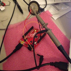
Rather than using a speaker, I wired up a little piezo element which I had soldered a couple of leads onto my junk pile. These disks are terrible at reproducing low frequencies and have strong resonances, but for this purpose, it was convenient. You can substitute a speaker if you like. It’s probably a good idea to use a little drive transistor with an 8 ohm speaker to provide more drive: you can see the basic idea here. It is nominally targeted toward mbed microcontrollers, but nothing about it is specific to those. Anyway, I hooked the positive lead of the element up to pin 9, and the negative lead to ground.

IMG_5699

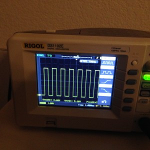
I also hooked up my oscilloscope so I could verify that the tone was coming out at the proper frequency. Indeed, it appears that it works just fine.

IMG_5697

Additionally, I made a few other small changes to my program. The prior version stored the static table in RAM, which is wasteful of a hundred or so bytes of RAM. It doesn’t sound like a lot, but there are only 2048 bytes of RAM available, so every little bit helps.

Addendum: If you want to generate nicer looking sine waves, you could do a lot worse than to use this circuit from Jason, NT7S which serves as a nice little oscillator. It’s a nice little Twin-T oscillator, followed by a very simple little amplifier. You could use an optocoupler in place of the key to drive it, or probably just key it with another 2N2222 or similar transistor.

Addendum2: If you want to go all out, a circuit like this one has a very pretty keying waveform.

[sourcecode lang=”cpp”]
//
// Simple Arduino Morse Beacon
// Written by Mark VandeWettering K6HX
// Email: k6hx@arrl.net
//
// This code is so trivial that I’m releasing it completely without
// restrictions. If you find it useful, it would be nice if you dropped
// me an email, maybe plugged my blog @ https://brainwagon.org or included
// a brief acknowledgement in whatever derivative you create, but that’s
// just a courtesy. Feel free to do whatever.
//
// At the request of Andy, I added support to use the Arduino Tone library
// to generate an audio signal (really just a square wave) at 700hz on
// pin 9 (can be any pin which supports PWM, on the Arduino Uno, those pins
// are 3, 5, 6, 9, 10 or 11, and are usually marked with a dash next to them).
//
// NOTE: the audio signals is just a square wave. It’s not got a great
// tone, and may click or chirp at the end. It’s mostly useful as a
// sidetone generator, and probably should not be fed into the mic input
// of a transmitter to send MCW.

// This defines the pin that will have the audio signal

const int sndPin = 9 ;

// Sound frequency (in Hz)
#define SND_FREQ (700)

// If you leave NOISY defined, the Arduino will print out each character
// as it is sent to the serial port. You might want to comment this out
// (put // at the start of the line) if you are especially cramped for
// memory, otherwise it doesn’t hurt to leave it in place, even if you
// don’t hook the serial port to anything.
//
// If NOISY is defined, then the size of the program is…
// Program: 4938 bytes (15.1% Full)
// (.text + .data + .bootloader)
//
// Data: 399 bytes (19.5% Full)
// (.data + .bss + .noinit)
//
// If NOISY isn’t defined
// Program: 2964 bytes (9.0% Full)
// (.text + .data + .bootloader)
//
// Data: 48 bytes (2.3% Full)
// (.data + .bss + .noinit)
//

#define NOISY

struct t_mtab { char c, pat; } ;

// Compared to my earlier version of this code, we can
// save some precious RAM by storing this constant table
// in flash memory.

const struct t_mtab morsetab[] PROGMEM = {
{‘.’, 106},
{‘,’, 115},
{‘?’, 76},
{‘/’, 41},
{‘A’, 6},
{‘B’, 17},
{‘C’, 21},
{‘D’, 9},
{‘E’, 2},
{‘F’, 20},
{‘G’, 11},
{‘H’, 16},
{‘I’, 4},
{‘J’, 30},
{‘K’, 13},
{‘L’, 18},
{‘M’, 7},
{‘N’, 5},
{‘O’, 15},
{‘P’, 22},
{‘Q’, 27},
{‘R’, 10},
{‘S’, 8},
{‘T’, 3},
{‘U’, 12},
{‘V’, 24},
{‘W’, 14},
{‘X’, 25},
{‘Y’, 29},
{‘Z’, 19},
{‘1’, 62},
{‘2’, 60},
{‘3’, 56},
{‘4’, 48},
{‘5’, 32},
{‘6’, 33},
{‘7’, 35},
{‘8’, 39},
{‘9’, 47},
{‘0’, 63}
} ;

#define N_MORSE (sizeof(morsetab)/sizeof(morsetab[0]))

#define SPEED (12)
#define DOTLEN (1200/SPEED)
#define DASHLEN (3*(1200/SPEED))

const int LEDpin = 13 ;

void
dash()
{
digitalWrite(LEDpin, HIGH) ; // turn on the LED
tone(sndPin, SND_FREQ) ; // and the sound output..
delay(DASHLEN);
digitalWrite(LEDpin, LOW) ; // then back off
noTone(sndPin) ; // and silence…
delay(DOTLEN) ;
}

void
dit()
{
digitalWrite(LEDpin, HIGH) ; // again, LED on…
tone(sndPin, SND_FREQ); // and sound…
delay(DOTLEN);
digitalWrite(LEDpin, LOW) ; // off…
noTone(sndPin) ; // quiet…
delay(DOTLEN);
}

void
send(char c)
{
unsigned int i ;
if (c == ‘ ‘) {
#ifdef NOISY
Serial.print(c) ;
#endif
delay(7*DOTLEN) ;
return ;
}
for (i=0; i<N_MORSE; i++) {
if (pgm_read_byte(&(morsetab[i].c)) == c) {
unsigned char p = pgm_read_byte(&(morsetab[i].pat)) ;
#ifdef NOISY
Serial.print(c) ;
#endif
while (p != 1) {
if (p & 1)
dash() ;
else
dit() ;
p = p / 2 ;
}
delay(2*DOTLEN) ;
return ;
}
}
/* if we drop off the end, then we send a space */
#ifdef NOISY
Serial.print("?") ;
#endif
}

void
sendmsg(const char *str)
{
while (*str)
send(*str++) ;
#ifdef NOISY
Serial.println("");
#endif
}

void setup() {
pinMode(LEDpin, OUTPUT) ;
pinMode(sndPin, OUTPUT) ;
#ifdef NOISY
Serial.begin(9600) ;
Serial.println("Simple Arduino Morse Beacon v1.0") ;
Serial.println("Written by Mark VandeWettering <brainwagon@gmail.com>") ;
Serial.println("Check out my blog @ https://brainwagon.org") ;
Serial.print("LED will blink on pin ");
Serial.println(LEDpin);
Serial.print("Sound will be generated on pin ");
Serial.println(sndPin);
Serial.println("") ;
#endif
}

void loop() {
sendmsg("K6HX/B CM87") ;

tone(sndPin, SND_FREQ) ;
delay(20000);
noTone(sndPin) ;
delay(3000) ;
}
[/sourcecode]

Minor tweak to my Hummingbird Camera…

March 28, 2015 | My Projects, Raspberry Pi | By: Mark VandeWettering

One thing I didn’t realize when I setup the Raspberry Pi camera to monitor my humming bird feeder was that it has a bright red led which turns on when the camera is enabled. In most cases, this light isn’t a big deal, but I am pointing it out the window, so the reflection of it is kind of annoying. You can see it in my earlier pictures, but I didn’t realize what it was until later, when I got this picture:

07-20150328182635-01

Luckily, it’s easy to disable. Just edit the file /boot/config.txt, and add a line which looks like:

disable_camera_led=1

and then reboot. Voila. All is fixed. This might be handy if you wanted to setup a stealth security camera as well. Just noted here, so I don’t forget.

Motion Detecting Hummingbird Camera: Prototype

March 28, 2015 | My Photos, My Projects, Raspberry Pi | By: Mark VandeWettering

Prototype CameraI like to see hummingbirds. They seem completely incredible to me, like little hyper Swiss Watches, buzzing around the garden. I’ve seen a few of them in our yard, but I’ve been meaning to encourage them showing up more, so I recently installed a feeder. While the syrup level has gone down, I have never caught one actually feeding.

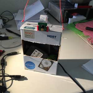
Of course, the way to solve this problem (as is true of all problems) is to apply technology! So, I quickly hacked together a little prototype camera that I could hang on my window and stare out at feeder. I’ve been thinking of doing this all week, and gotten proofing. In the end, I wasn’t getting anywhere, so this morning I decided on what I thought was the simplest possible prototype. I took one of my old Raspberry Pi’s, a DLINK powered USB hub to power it, and a Raspberry Pi camera, and taped them all in the cardboard box for an old laptop hard drive. My original idea was simply to duct tape it to the window facing the bird feeder, but a quick trial of this wasn’t promising: the duct tape kept relaxing, and the box was slowly drifting down. So, instead I got some wire and made a little hanger that would attach to two paperclips that I jammed in each side. It isn’t the greatest way to go, but it works.

I hung it from the top of the blinds in the kitchen, aimed it only very coarsely, and took my first picture by logging in and running raspistill. The aim isn’t very good, I only got the feeder at the edge, but this is just a prototype: if I start getting pictures of hummingbirds, I will refine the design/aim, and probably mount the camera outside so I can be a bit closer.

mingbird Feeder Prototype

Of course all you see are the drought stricken side of my hill, but if I get any pictures of birds, I’ll be posting them soon.

Addendum: I wandered outside as a quick test of the camera. While I am bigger than a hummingbird, I didn’t have any problem tripping the camera. I am concerned that the small, fast motion of a hummingbird may not be sufficient to trip the camera, but we shall see.

01-20150328135843-01i

A couple of additional words on the software. I use the “motion-mmal” program, a port of the popular “motion” program that is widely used on Linux with conventional webcams, but has been extended to use the Raspberry Pi camera, which are both high quality and inexpensive. The way I have this configured is that it does motion detection on a downresolution version of the video feed, and when it detects motion, it dumps the frame with the biggest difference to a local disk. Eventually, I may try to get it to capture video, and/or upload it automatically to google drive like I have done before for my cat camera. More later.

Addendum2: Huzzah! Within an hour of setting this camera up, I got my first picture! I guess it works. I’ll have to get it aimed a bit better and see how often I can catch birds, and maybe try to set it up to do motion capture too, not just stills.

04-20150328144545-02

Tiny BASIC on a Tiny Display…

March 25, 2015 | Arduino, My Projects | By: Mark VandeWettering

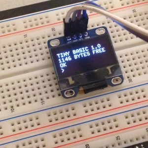
IMG_5694Early in 2012, I posted a small version of Tiny BASIC that I had adapted to run on the Arduino. It is based upon code which was written by Mike Field, and based upon an earlier version of TinyBasic for the 68000 written by Gordon Brandly, which owes its roots to Palo Alto Tiny BASIC, written all the way back in 1976 as one of the first examples of a free software project.

I had done a couple of extensions to that code to include simple commands to read and write digital and analog I/O pins, implement simple delays, and even generate simple tones. But then the project languished. Tonight, I dusted that code off and made a number of improvements.

First of all, the original program didn’t have very much memory to store programs. This is due largely to the fact that the Arduino Uno has only 2048 bytes of RAM to use for any purpose at all, so every byte is important. What I realized in staring at the code tonight was that a significant number of bytes (well, significant in this context) number of bytes were used to store some static data tables that defined the keywords and functions available to the interpreter. By changing those to “const” tables, I could move them to be stored in the flash (read-only) memory, and free up a couple hundred additional bytes of storage. That may not sound like a lot, but every little bit helps. Now when the system boots, it has 1146 bytes of memory to store programs.

Next, I thought it would be fun to use the OLED display that I’ve been tinkering with to act as an output display. I did a little quick math: I liked an 8×13 font for display, so that meant I could just get 4 lines of 16 characters on the display. That meant that I’d need 64 bytes of ram to store the contents, but that should be a small price to pay. I wrote up a new “outputchar” routine that would deposit printed characters at the the cursor location in the memory buffer, and then increment the cursor position, and handle scrolling. Refreshing the LED screen is not very fast, since it is occurring over the I2C bus, so I thought about a couple ways to “batch” the printing of individual characters, and only refresh the screen when a bunch of output has occurred, only when the screen was “dirty”, and when a time interval had passed. It took me a couple of tries to get this right, but it seems like it worked.

I filmed a short demo of the system working. The keyboard input is still coming from the serial monitor, but display is going to the OLED.


I’d be happy to release the code in a few days after I tinker a bit more. Right now, command line editing is a bit rough, and I’d like to get that working better.

Addendum: This code (the original authors, not mine) has served as the basis for additional versions, some more capable than mine. TinyBasicPlus includes commands to save and chain programs from the internal EEPROM, and store them to SD cards. Very neat.

Using the Parallax PING))) ultrasonic distance sensor

March 24, 2015 | Arduino, My Projects | By: Mark VandeWettering

I intended to play around with some of the NRF24L01 radio modules I have around, but my brain didn’t feel up to it after a day of debugging. So, instead i dusted off a Parallax PING))) sensor that I’ve had around for a long time. I thought it might be fun to see if I could use the OLED display to display the distance measured by the sensor. While watching Agents of Shield, I came up with the following tiny bit of code, demo’ed below.


[sourcecode lang=”cpp”]
#include "U8glib.h"

U8GLIB_SSD1306_128X64 u8g(U8G_I2C_OPT_NONE);

// _
// ___ (_)__ ___ _
// / _ \/ / _ \/ _ `/
// / .__/_/_//_/\_, /
// /_/ /___/
//
// A simple rangefinder program using the Parallax PING sensor
// Writes display out to my tiny OLED display…

const int pingPin = 7 ;

char dbuf[10] ;

void
draw()
{
u8g.setDefaultBackgroundColor();
u8g.drawBox(0, 0, 128, 64);
u8g.setDefaultForegroundColor();
u8g.setFont(u8g_font_10x20);
u8g.drawStr(14, 42, dbuf);
u8g.drawStr(94, 42, "cm");
}

void
setup()
{
Serial.begin(9600);
}

void
loop()
{
long duration ;

pinMode(pingPin, OUTPUT);
digitalWrite(pingPin, LOW); // Make sure we drive the pin low…
delayMicroseconds(2);
digitalWrite(pingPin, HIGH); // Pulse high for 5us
delayMicroseconds(5);
digitalWrite(pingPin, LOW); // Finish the pulse…

pinMode(pingPin, INPUT); // Get ready to read…
duration = pulseIn(pingPin, HIGH); // Wait for the echo pulse to drop back to low

// The speed of sound is 29 us per cm… j

float cm = duration / (29. * 2.) ;
dtostrf(cm, 8, 2, dbuf) ;

u8g.firstPage() ;
do {
draw() ;
} while (u8g.nextPage()) ;
}
[/sourcecode]

Addendum: I’ve been snapping short videos with the Vine app, and then posting them to Twitter and Facebook. Irritatingly, these don’t seem to actually play properly when I embed them back in my website. I’ll figure out a better workflow next time.

Addendum2: Goofing around a little, it appeared that this sensor worked out until about 70cm or so, and then snaps to 340cm. Not sure what that is about: the sensor should behave more accurately than that. I’ll experiment more tomorrow. I should also note that these Parallax sensors are fairly pricey: list price is almost $30. I like the Parallax guys a lot, but that’s pretty spendy. You can get much cheaper modules on Ebay, with costs as low as around $1.50. I haven’t got any of these, but they are worth trying, although various sources on the web suggest that you might get what you pay for. Try googling for “HC-SR04” for more information.

My version of minilife2 for the Arduino…

March 24, 2015 | Arduino, My Projects | By: Mark VandeWettering

Without a lot more explanation, I did a bit more work on my implementation of Conway’s life, reducing the overhead so I can implement the full 128×64 bit resolution of the OLED display. I also hardcoded an initial pattern: the classic Gosper glider gun. It runs at about 1.625 frames/second, so a new glider is emitted every 18 seconds or so. Eventually, they wrap around and destroy the glider gun by colliding with it. I can think of a few more optimizations that are easy, but I doubt they are very important.


[sourcecode lang=”cpp”]
#include "U8glib.h"

U8GLIB_SSD1306_128X64 u8g(U8G_I2C_OPT_NONE);

#define XSIZE (128)
#define XMASK (127)
#define XSIZE_UINT8 (XSIZE/8)
#define YSIZE (64)
#define YMASK (63)

// We use the extra lines as buffer space…
uint8_t c[YSIZE][XSIZE_UINT8] ;

#define MODX(x) (((x)+XSIZE)&XMASK)
#define MODY(y) (((y)+YSIZE)&YMASK)

#define ISSET(a, x) \
(a[MODX(x)>>3] & (0x1<<(MODX(x)&7)))

#define SET(a, x) \
a[MODX(x)>>3] |= (0x1<<(MODX(x)&7))

#define SETXY(a, x, y) \
a[y][x>>3] |= (0x1<<((x)&7))

#define CLR(a, x) \
a[MODX(x)>>3] &= ~(0x1<<(MODX(x)&7))

void
initrandom()
{
int i, j ;
for (j=0; j<YSIZE; j++)
for (i=0; i<XSIZE_UINT8; i++)
c[j][i] = random(256) ;
}

void
initgun()
{
memset(c, 0, sizeof(c)) ;
SETXY(c, 70, 28); SETXY(c, 68, 29); SETXY(c, 70, 29); SETXY(c, 58, 30);
SETXY(c, 59, 30); SETXY(c, 66, 30); SETXY(c, 67, 30); SETXY(c, 80, 30);
SETXY(c, 81, 30); SETXY(c, 57, 31); SETXY(c, 61, 31); SETXY(c, 66, 31);
SETXY(c, 67, 31); SETXY(c, 80, 31); SETXY(c, 81, 31); SETXY(c, 46, 32);
SETXY(c, 47, 32); SETXY(c, 56, 32); SETXY(c, 62, 32); SETXY(c, 66, 32);
SETXY(c, 67, 32); SETXY(c, 46, 33); SETXY(c, 47, 33); SETXY(c, 56, 33);
SETXY(c, 60, 33); SETXY(c, 62, 33); SETXY(c, 63, 33); SETXY(c, 68, 33);
SETXY(c, 70, 33); SETXY(c, 56, 34); SETXY(c, 62, 34); SETXY(c, 70, 34);
SETXY(c, 57, 35); SETXY(c, 61, 35); SETXY(c, 58, 36); SETXY(c, 59, 36);
}

void
setup()
{
#ifdef TIME_ME
Serial.begin(9600) ;
#endif

randomSeed(analogRead(A0));
initgun() ;
}

void
draw()
{
u8g.setDefaultBackgroundColor() ;
u8g.drawBox(0, 0, 128, 64) ;
u8g.setDefaultForegroundColor() ;
u8g.drawXBM(0, 0, XSIZE, YSIZE, (const uint8_t *) c) ;
}

void
line(const uint8_t *a, const uint8_t *b, const uint8_t *c,
uint8_t *out)
{
int i ;
for (i=0; i<XSIZE; i++) {
int sum = 0 ;
if (ISSET(a, i-1)) sum ++ ;
if (ISSET(a, i )) sum ++ ;
if (ISSET(a, i+1)) sum ++ ;
if (ISSET(b, i-1)) sum ++ ;
if (ISSET(b, i+1)) sum ++ ;
if (ISSET(c, i-1)) sum ++ ;
if (ISSET(c, i )) sum ++ ;
if (ISSET(c, i+1)) sum ++ ;

if (ISSET(b, i)) {
if (sum == 2 || sum == 3)
SET(out, i) ;
else
CLR(out, i) ;
} else {
if (sum == 3)
SET(out, i) ;
else
CLR(out, i) ;
}
}
}

void
loop()
{
int j, op ;
uint8_t obuf[2][XSIZE_UINT8] ;
uint8_t otmp[XSIZE_UINT8] ;

#ifdef TIME_ME
unsigned long time_start, time_stop ;

time_start = millis() ;
#endif

line(c[YSIZE-1], c[0], c[1], obuf[0]) ;
line(c[0], c[1], c[2], obuf[1]) ;
op = 0 ;

// We need this for the wrap around.

memcpy(otmp, c[0], XSIZE_UINT8) ;

for (j=2; j<YSIZE-1; j++) {
memcpy(c[j-2], obuf[op], XSIZE_UINT8) ;
line(c[MODY(j-1)], c[j], c[MODY(j+1)], obuf[op]) ;
op = 1 – op ;
}

// We still have three lines we need to copy back…
// And one more buffer to compute with line()

memcpy(c[YSIZE-3], obuf[op], XSIZE_UINT8) ;
line(c[YSIZE-2], c[YSIZE-1], otmp, obuf[op]) ;
op = 1 – op ;
memcpy(c[YSIZE-2], obuf[op], XSIZE_UINT8) ;
op = 1 – op ;
memcpy(c[YSIZE-1], obuf[op], XSIZE_UINT8) ;

// compute one generation..

u8g.firstPage() ;
do {
draw() ;
} while (u8g.nextPage()) ;

#ifdef TIME_ME
time_stop = millis() ;

Serial.print(time_stop – time_start) ;
Serial.println() ;
#endif
}
[/sourcecode]