Simulation experiments with LT-Spice…

January 20, 2013 | electronics, Homebrew CPU | By: Mark VandeWettering

Yesterday, I mentioned Rory’s excellent introduction and exploration into DTL logic. He covers some of the basics here, including circuits for all the basic gates: AND, OR, NOT and NAND. The AND and OR gates are interesting, because they consist entirely of diodes and resistors. They do have the drawback that they are “lossy” (the technical term is non-regenerative). They experience a voltage drop across them, so they can’t be cascaded forever, as the voltage drop continues with each gate, and they ultimately lose the ability to compute effectively. The NOT and NAND gates on the other hand use a typical bipolar NPN transistor, and use the amplifying capability of transistors to regenerate the signal.

I was interested in a couple of things about the circuit though, so I fired up LTSpice for a little computational experiment.

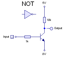
I have played around with simple inverters like this one, which Rory mentioned which I always thought of as an effective inverter. But Rory mentioned that it was unable to run at higher speed (say, around 1Mhz). I was also interested in how the choice of diode affected the circuit.

So, I built it. Rory used BAT42 Schottky diodes, which weren’t in my component catalog, so instead I substituted a 1N5818 diode.

dtl-nand

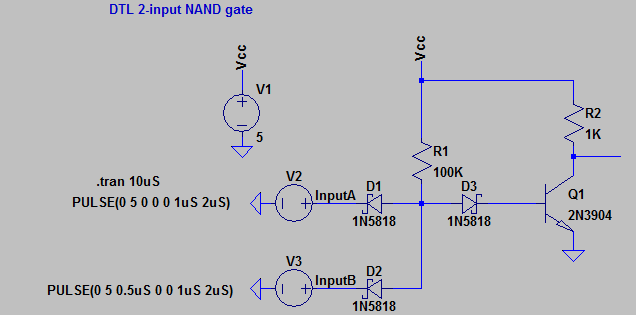
And sure enough, it works pretty darn well. I coded up a 500kHz clock, and the output looks pretty clean. I fed it two pulse trains one delayed with the other, and it looks pretty good.

trace

If you substitute some of the cheap diodes I have on my bench (like a 1N914 or a 1N4148) you can see that it works pretty well at frequencies around 1000Hz, but fails miserably at frequencies of 1Mhz. Ditto for the simplified inverter circuit we looked at above: it simply can’t function at 500khz. Superimposed with the NAND pulse train, here is the output of the simplified inverter wired to InputA. As you can see, the input pulses just turn into a feeble triangle wave.

inverter

I suspect that thinking about why this is will lead me to a much more robust understanding of transistors.

Tiny-Tim: A DTL computer (in progress)

January 20, 2013 | electronics, Hardware, Homebrew CPU, Homebuilt CPUs | By: Mark VandeWettering

Previously, I had linked to Rory Mangles’ experiments with relay based computers. He had an incredible build of a relay logic computer called Tiny-8 which used paper as program mamory, inked with a pattern which could be read by photo sensors to sequence the control logic in his computer. I thought it was amazing. But surfing back to his website, he appears to now by working Tiny Tim, a diode-transistor logic (DTL) computer, made from discrete 2N3904 transistors and Schottky diodes. Sadly, there isn’t much actual build here yet (this update is six months old) but there is some good information, and I hope that he’ll pick up the project again.

Here is a link to his video of a simple flip flop:


A new little computer: the Raspberry Pi…

January 6, 2013 | Raspberry Pi | By: Mark VandeWettering

Sorry it’s been a while since I wrote anything here. The simple fact is that I haven’t done a lot that’s very interesting lately. But Carmen did buy me a Raspberry Pi for Christmas, and I’ve been playing with it a bit. As it happens, we had a power outage over on the 26th, and when my rapidly aging FreeBSD server (a 1Ghz Via C3 Nehamiah processor, released in 2003, if memory served) rebooted, one of its drives seems to have failed. I mostly use this machine for an ssh and IRC server, some local web and file serving, and the odd bit of Python and C programming. I have been considering replacing this 10 year old machine, but until I get around to putting something reasonable in it’s place, I thought I’d see if the Raspberry Pi could serve.

And the answer is yes, it can.

I installed the Raspbian distribution of Debian, and plugged it into my router. Enabled ssh, and voila! Works great. Well, it’s pretty slow. I have a class 4 4GB card serving as its only storage, which is not exactly brilliant, and the 700Mhz clock rate is pretty… well… slow, even by comparison to the 1Ghz machine it’s replacing. But it does work! It’s even got an X server, which isn’t exactly zippy, but which does work.

For fun, I thought I’d give it a bit more of a test. I installed simh, and then transferred my TOPS-10 disk images over. The Raspberry Pi actually makes a pretty nice little PDP-10 simulator. I’ll have to benchmark it later, but it seems to work just fine.

I’ll have more details later, but for $35, it’s a lot of computer. Barely more than an Arduino Uno, but with a lot more capability.

Highly recommended.

What’s today’s Mayan Long Count date?

December 14, 2012 | My Projects | By: Mark VandeWettering

I wanted to know.

I read up on the Mayan calendar.

It was easy to code up in Python:

[sourcecode lang=”python”]
#!/usr/bin/env python

# This code is completely untested, it doesn’t do anything relative
# to timezones or the like. It does appear to broadly function.
#
# 1 k’in == 1 day
# 1 winal = 20 k’in or 20 days
# 1 tun = 18 winal or 360 days
# 1 k’atun = 20 tun or 7200 days
# 1 b’ak’tun = 20 k’atun or 144000 days

import time
from datetime import date

def calc(n):
# n is the days since the start of the latest b’ak’tun
# which occurred on September 18, 1618
baktun = int(n / 144000)
n = n – baktun * 144000
katun = int(n / 7200)
n = n – katun * 7200
tun = int(n / 360)
n = n – tun * 360
winal = n / 20
n = n – winal * 20
kin = n
return map(lambda x : str(x), [12+baktun, katun, tun, winal, kin])

today = date.today()
s = date(1618, 9, 18)

print "Mayan Long Count = %s" % (‘.’.join(calc(int((today – s).days))))
[/sourcecode]

Today is 12.19.19.17.13. In 7 days, the right most place will roll over, and the date will be 13.0.0.0.0, starting a new b’ak’tun.

Or the world will end. Enjoy!

Another swappable fuselage from Busybee TV

December 6, 2012 | Radio Controlled Airplanes | By: Mark VandeWettering

The guys over at flitetest have a great series on building airplanes around a swappable fuselage. The basic idea is to house the receiver, esc, and battery in a fuselage that can be easily attached and detached to different wing setups, essentially giving you different planes without having to duplicate all the same receiver/ESC in each. It’s a neat idea. Today, I noticed this video from Busybee TV, showing his own version of the swappable with a cute twist. He built it significantly smaller (my guess is about 60% as large as the flitetest version) which means that the wing loading is significantly lower, and you can hold the wings in place with magnets. Oh, and it costs about $50. He demonstrates to mini-airplane wingsets. Build videos are supposed to be coming soon. Check it out:


Some small experiments with Arduino sound…

November 29, 2012 | Arduino, My Projects | By: Mark VandeWettering

Last year, I spent a little bit of time to create a set of blinking Christmas lights that I could mount in a hat. It was powered by an ATtiny13 and mounted in an Altoids tin. While setting up my Christmas tree last weekend, I found them, and they still work. In case you missed it, here are some of the videos I did at the time:


It was kind of fun, and still works, so I’ll probably be wearing it around. But I thought to myself: what could I do to make it better?

The obvious thing to me was to try to add more lights, more patterns, and music. Rather than use a naked ATtiny13, I thought that I would just go ahead and use an Arduino. I have an Arduino Mini that I got to use in a radio beacon experiment that I haven’t gotten to yet, so that seemed like a good idea. The question was then: what could I do?

I came up with these ideas:

  • More lights. At $.99 a string, I could put a lot more light strands in place. That would make fancier “chase” effects possible, and generally just look cool.
  • More effects.
  • A better hat! The missus has a new sewing machine, and could probably use a new project. I have a big head, so finding a Santa cap that fits is always a bit of a chore, and if we made our own, we could add pockets for batteries and sew in the wiring to make it neater.
  • Sound. It would be cool to add a small speaker and amplifier, and play music with synchronized light effects.

I don’t think any of this is especially hard. The only part I hadn’t really done before (other than the sewing bit) was sound. So, last night I started reviewing what libraries existed for sound on the Arduino. I actually have a WAV shield lying around, but I was looking for something a bit more minimal: I didn’t really care to use a full shield, both for size and for just a sense of minimality. I kind of wanted to store a few Christmas tunes in the on-chip flash, and then synthesize some high quality (well, decent quality) audio directly.

Which lead me to the Mozzi sound framework.

The Mozzi sound framework for Arduino

Mozzi seems to generate some pretty cool sounds (samples here) and is a pretty neat framework. I decided to give it a whirl last night. I was somewhat delayed by trying to get the Arduino software installed on my new Windows 8 laptop. Apparently the drivers that you need aren’t sufficiently digitally signed for Microsoft to trust them, and you have to go to some effort to disable those checks and get them to install. But once I got that sorted out, I didn’t have any problem downloading and playing with the Mozzi library. To hear the samples, I just hooked a high impedance earphone from a crystal radio to pin 9 and ground, and they worked as expected. The Mozzi webpage actually recommends a bit of output filtering: they have a 6Khz lowpass filter followed by a 16Khz notch filter to get rid of the PWM noise. The design is quite simple RC filter and uses very common values of components, so it should be pretty easy to build. I spent a few minutes entering the schematic into LTSpice, and it seems like it works as expected, and should help audio quality considerably.

Going forward, I need to find some decent Christmas tunes (perhaps in ABC notation like these, although I’d like more complex, polyphonic tunes) and figure out how to synthesize some nice sounds in the incredibly limited time available, as well as control the switching of the LEDs themselves. Stay tuned for more experiments.

My son at the drive through…

November 28, 2012 | Photos | By: Mark VandeWettering

I don’t think he was at the local Sonic drive-through window.

Okay, this doesn’t have much to do with my normal blog topics: it’s just a picture of my son working his day job. Your country thanks you for your service, and your mom and I are very proud of you. And the glasses are very stylish.


An “So” series foamflyer…

November 21, 2012 | Radio Controlled Airplanes | By: Mark VandeWettering

Today I spent a lot of time making bread and pumpkin cheesecake for tomorrow’s Thanksgiving day feast, but in between I decided to build some more parts for a “So” twin boom foam flyer, using the KFm3 wing that I photographed yesterday. My goal wasn’t so much to build a flying plane today, but to just test the design out, and see if there were any difficulties or tweaks to be made. So, I made two twin triangular booms, the 13″x4″ stabilizer, tail fins, and the body. Here’s the result:

It’s a fairly nice looking design. The twin booms and stabilizer presented no serious issues, except for maybe alignment: making sure they are parallel and at right angles to the wings and stabilizers. I cut the internal bevels on the boom freehand, which made them look a little rough, but that presented no real problem once they are glued and folded. The fuselage body was a bit trickier: the instructions call for cutting a 36″ long strip, 1″ wide that separates the two sides. I cut a pair of 1″ wide strips, since the stock that I had is maximum of 30″ wide. I free handed the curve at the front of the fuselage, cutting both sides simultaneously. I then glued the strip along once side with hot glue, then spread hot glue on the other side and lowered it down. It isn’t perfect, but seems okay. I haven’t covered it with packing tape: my skills at covering flat sheets are pretty good, but irregular shapes seem a bit trickier. I’m pondering building a similar plane, but using the Experimental Airlines 2.5″ square fuselage.

But it looks pretty good. I’ll be able to weigh the model and work out the wing loading and some of the balance issues. I’ll also be able to think about how to place the servos, receiver and battery. I may just hang it from the ceiling of my office.

A few simple foamboard wings…

November 20, 2012 | Radio Controlled Airplanes | By: Mark VandeWettering

Okay, I haven’t had much time to work on RC airplanes. I’ve been meaning to try to find something a little tamer than my Nutball to fly (it seems to be a bit twitchy) but I haven’t really done too much other than watch videos on YouTube and scout around on the rcgroups forums for inspiration. But I have been thinking alot about wings, and wing fabrications. I ended up making three different wings from Dollar Tree foamboard, and thought it might be nice to show what they look like, and what I learned in building a few of them.

The first of these is the so-called Armin Wing, championed by Ed on the Experimental Airlines channel. I’ve made a few versions of these. The nice thing about these is that they have a nice airfoil shape. The version that I have here isn’t the fancy version, with the knife-edge trailing edge, but it’s pretty nice. I used a piece of 3/16″ dowel to stiffen it (carbon fiber would be better, but I was just experimenting).

Ed’s videos show in great detail how to make these, if they interest you, go review those. The one disadvantage is that they are a little bit involved, compared to the two designs that follow, but they aren’t really difficult, and I suspect that they might perform better than simple KFm airfoils, although mine have pretty blunt leading edges, which could make for higher drag than you might like, at least for high speed flights.

While watching flitetest’s video on Airfoils, they constructed a KFm3 style stepped airfoil to replace a damaged wing on their Cessna model. They didn’t go into any details on how they did it, but I thought it might be pretty easy. The airfoil has steps at 50% and 75% of the wing chord, so I cut a piece which was 12″x30″, and another which was 6″x30. I folded the 12″x30″ piece 4″ back from the leading edge, and clamped and glued it around the 6″ piece, resulting in a wing with an 8″ chord, and three thicknesses of foamboard. Because there was so much area to be glued, I didn’t use hot glue, I used Gorilla glue, and clamped it for a couple of hours. It worked, but also had a blunt leading edge. Not sure I liked it.

The “So” design that I linked in my last posting was also a KFm3 wing, but constructed a bit differently. This wing has a 6″ chord, so you begin by cutting a 9″x30″ of foamboard, and then score halfway through it 3″ back from one edge. You then cut a shallow bevel on either side, so you can fold it back. A piece 1.75″ wide is first glued 1.5″ back from the trailing edge, and then the bevelled part folded back and glued to the top edge of the 1.75″ piece. Okay, that’s a crappy description, but here’s the result. The bevel allows the leading edge to be sharper than the previous one.

All three seem credible designs. I probably will use the third technique if I go with the KFm3 style wing. I like the So design, so I might try putting one together shortly, although I’m considering the “trainer” mods (polyhedral wing, with rudder rather than aileron). But the Armin wings aren’t that much harder, and make for kind of a spiffy looking wing.

Stay tuned for more foamboard madness. The cat is enjoying playing with the scraps at least.

Addendum: The KFm3 wing can be scaled up. Check out this video of a 96″ version (almost 5x the size of the one I just put together):


An interesting foamboard airplane with a single aileron…

November 19, 2012 | Radio Controlled Airplanes | By: Mark VandeWettering

I’m constantly on the lookout for interesting and simple airplane designs. This design from foamflyer is interesting in a couple of different ways. First of all, it’s made from cheap dollar tree foamboard, which is nice. It has an overall pleasing shape with a nice KFm3 style airfoil, constructed a bit differently than the one that I made as a test recently. It’s a pusher prop configuration (which might be nice for FPV/video) and most interestingly, it has just a single aileron. I like it!

The build log appears on this page on the rcgroups forums, and includes lots of build details. Really nice. He’s also got a terrific website chock full of two hundred planes that he’s constructed. Great stuff.

Addendum: The lack of dihedral may make this a less than ideal trainer aircraft, but one of the commenters constructed a similar airplane with a polyhedral wing to add dihedral, and used a rudder-elevator setup instead of the single aileron (my guess is the single aileron doesn’t work as well with the dihedral in place). Also worth looking into!

The Clark Y airfoil…

November 15, 2012 | Radio Controlled Airplanes | By: Mark VandeWettering

I snapped awake at 5:30AM this morning, and couldn’t get back to sleep, so I started a loaf of bread to bake later tonight, and then settled in to thinking about airfoils some more. I had seen references to the “Clark Y” airfoil, but didn’t know how it was defined, so I set out to figure it out. A few minutes of googling revealed a fascinating resource, the UIUC Airfoil Data Site. It has data definitions for literally hundreds of airfoil profiles, including coordinates for the Clark Y. I then dusted off my dim knowledge of gnuplot to draw this (properly scaled) version of the airfoil.

There is a trick to getting gnuplot to work. Here’s the set of commands I used:

set terminal png size 1024,256
set size ratio -1
set ytic .1
set xlabel "Clark Y Airfoil"
plot "clarky.dat" with lines

(You could probably make it look prettier with a bit more work.) The important bit is to set the size ratio: without it gnuplot will change vertical and horizontal scales to fit the data in the window.

Okay, off to make breakfast.

More on airfoils…

November 14, 2012 | Radio Controlled Airplanes | By: Mark VandeWettering

As I was staring at the cross sectional diagram of the Armin wing I constructed yesterday, I began to think about airfoil shapes in general. I knew from reading done years ago that there were standardized ways of describing airfoil shapes, but didn’t recall any details. I didn’t have a copy of Abbot’s Theory of Wing Sections, and I loaned Mark H. my copy of Simon’s Model Aircraft Aerodynamics, so I had to turn to Google and Wikipedia to sate my desire for knowledge.

A few minutes of searching uncovered this Wikipedia entry on NACA airfoils. It’s pretty helpful, and includes formulas for generating the airfoil profiles of a wide variety of standard wing shapes. I hacked together a quick python program to generate the profile coordinates for 4 digit NACA airfoils, and as soon as I verify the results, I’ll post the code here. It won’t be hard to use this to generate a PostScript/PDF file which you could then directly print to make templates.

A bit more searching revealed this repository of Public Domain Aeronautical Software which included this implementation of a program to compute airfoil profiles for NACA wings. It’s written in “modern FORTRAN”, which isn’t my preferred language of choice, but I think it will be excellent to use it to verify the profiles produced by my Python code.

Just a tease, here’s some GNUplot output for a 6412 airfoil (the wing is fairly cambered with the maximum occuring at 40%).

The NACA 4 Digit 6412 airfoil. Not checked, and not properly to tscale

Ponderings on the Armin Wing…

November 13, 2012 | Radio Controlled Airplanes | By: Mark VandeWettering

Ed over at the Experimental Airlines Youtube channel has a nifty way of constructing wings for RC airplanes out of cheap Dollar Tree foamboard. Last night, I was feeling kind of brainless, so I decided to practice my arts and crafts by constructing another, this time using a piece of 3/16″ dowel to stiffen it. When I was done, I thought it might be nice to figure out how it really ranks as an airfoil. For that, I needed two things: some accurate measurements, and a program to do some simulation on the wing. I haven’t got as far as the second, but I took out my cheapy Harbor Freight calipers and took some measurements, and created the following scale drawing. I didn’t bother computing nice spline curves for the top surface, but the leading edge is pretty close. The back doesn’t use Ed’s nifty tapered tape edges: I just put a bevel on the base, and then glued the top down, so it’s basically the thickness of the 1 layer of foam board at the back. Anyway, here’s a PNG, if you click on it, you should get a 300dpi version which is lifesized.

Click for full scale 300dpi PNG of my Armin Wing, 7″ Chord…

I’ll try to get this into an airfoil simulator, and compare it to other simple wings (plates and KFM2 wings, hopefully) to see how it compares. I also want to get a precise weight for the wing, so I can figure out how the lift and weight compare).

Anyway, that’s what passes for arts and crafts at my house. Stay tuned.

Addendum: Josh and Josh over at flitetest have a nice video I hadn’t seen before on airfoils. It wasn’t super technical, but it did show an interesting KFm style stepped airfoil made from what appears to be the same Dollar Tree foam I was using. I had made one for my glider prototype that was a KFm2 airfoil (two layers, with the step at 50%), but they use one that appears to be more like a KFm3 airfoil, with the bottom and top layers created from just one piece, folded over a middle piece. What’s especially cool is that they used it to replace the conventional (and complicated) wing for one of their Cessna models, and it seemed to work great. I’ll have to try making one of those too.

Papers on Miniature Aerial Vehicles and Vision-based Obstacle Avoidance

November 6, 2012 | Radio Controlled Airplanes | By: Mark VandeWettering

I’m pretty interested in autonomous vehicles, and because of the wide availability of cheap electronics and compute power, experimentation in this realm is increasingly within the grasp of amateurs. I like the idea of building small aerial drones which can not only follow a predetermined coarse, but can also work to avoid obstacles and the like.

Today I found a press release for a paper “Low-Power Parallel Algorithms for Single Image based Obstacle Avoidance in Aerial Robots”, which seemed right up my alley. A quick Google revealed this web page, containing links to their papers. The math involved is a little beyond the casual, but I think I’ll be able to sort it out. Very nifty stuff, bookmarked for later.


Thoughts go out to all my readers on the East Coast…

October 30, 2012 | News | By: Mark VandeWettering

If you or your loved ones are in the areas affected by Sandy, you may not be able to read this, but my thoughts are with you all. If you aren’t in the affected areas, considering helping out in the relief efforts by donating either money or blood to the Red Cross. You can donate $10 by sending a text to 90999, or go to the Red Cross website and donate with a credit card or Paypal. The bad weather is likely to cause shortages of blood and platelets, so finding a donation center for blood would be a great idea as well.

Hang in there!