Post Field Day Report on K6HX Beacon Operations…

July 1, 2019 | My Projects | By: Mark VandeWettering

So, part of my incentive on working on my WSPR beacon was one of my coworkers decided to try to do some operating from the local Emeryville Marina, and I thought it might be nice to use the opportunity to try to pack up my WSPR setup and see if I could get some spots using solar/battery power.

I wrote up some of the early experimentation to get the beacon working, but as of then I hadn’t actually gotten on the air. To do that, I needed two things: an antenna and (to be a good RF citizen) a low pass filter to make sure that I wasn’t scattering horrible harmonics everywhere. While it was true that I was outputting a scant 10mw, I thought that being a good citizen was important.

I had some yellow T37-6 cores lying around from a previous bout of homebrew exploration, and dug out an article on constructing harmonic filters by the awesome (but sadly SK) George Dobs, G3RJV. I dug out some copper clad and wired up the filter using some islands that I punched out of scrap copper clad board. I am a total novice at this, so the board layout is terrible and stupid, and the leads are too long: in short, everything I did should be viewed with skepticism.

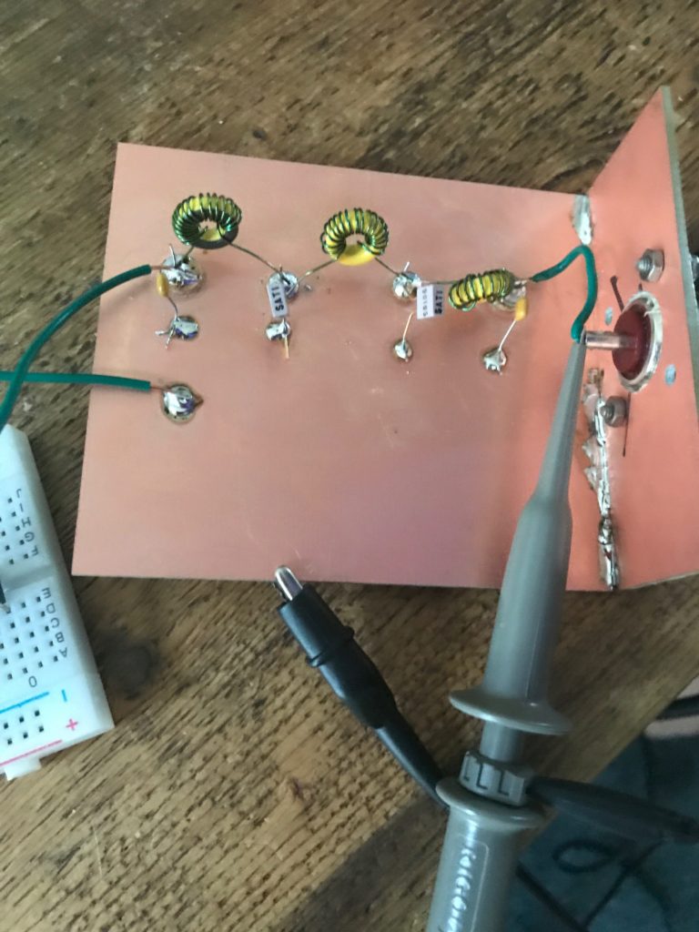
But as crappy as it is, it seemed to work. I snapped a quick picture of the output as it goes to my antenna, and the previously ugly triangle-ish wave now resembles a reasonable sine wave.

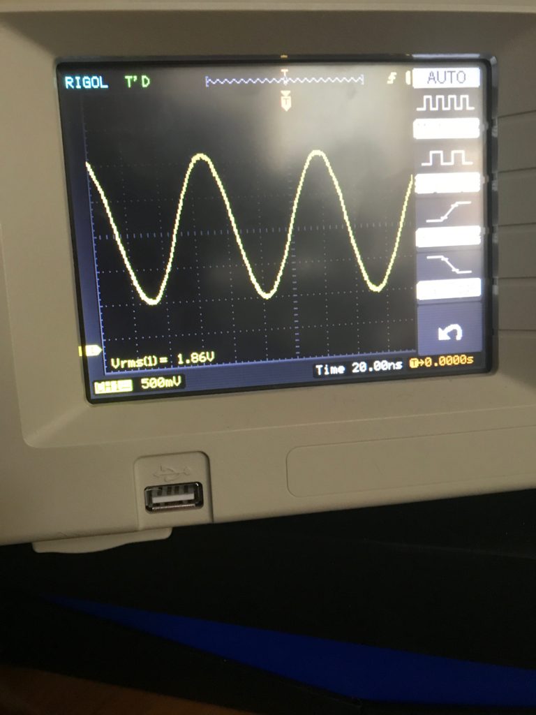
I must admit that I was somewhat befuddled by the Vrms as measured by my scope. The equation for output power suggests that power equals Vrms squared divided by the resistance. If we assume my antenna was a nominal 50 ohms (it’s not, but let’s pretend) then this would indicate an output power of nearly 70mw, which doesn’t really make sense. My antenna had only been “tuned” in the grossest sense, and probably had an SWR of around 2.5:1, which suggests that it’s characteristic impedance was probably a lot higher. For the purposes of WSPR, I configured my output power as 20mw, which I thought was probably still generous, but in the right ballpark. I made a note to myself to figure this out later.

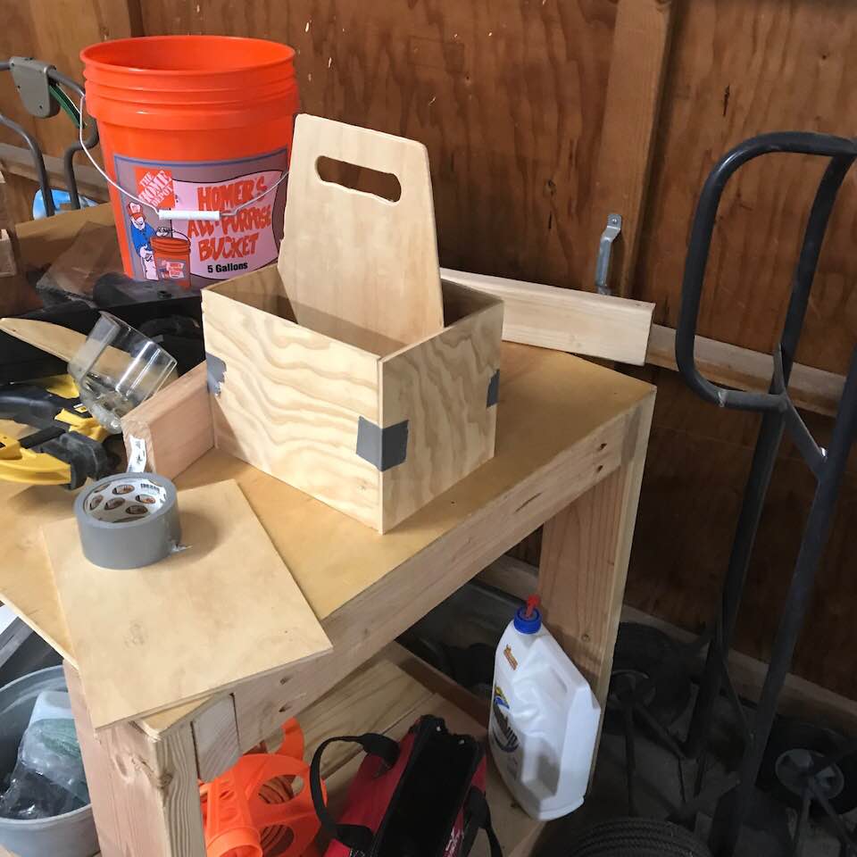
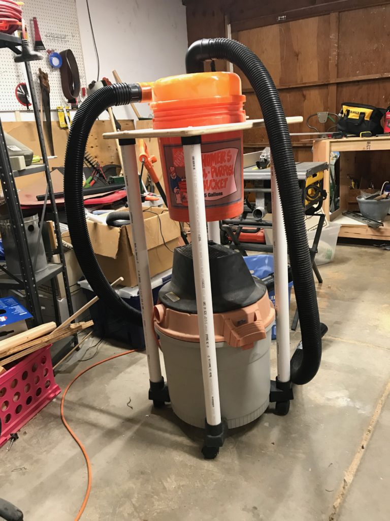
I still needed an antenna. While cleaning my garage, I found a pair of 20m whip antennas and an MFJ 347 mini dipole mount. I mounted these on a small piece of conduit, and then built a quick stand to hold it up, consisting of a 5 gallon bucket, a small round of particle board that I had left over from another project, and four pieces of two by fours to act as feet. Here it is, setup on my back patio. Yes, I know that the antenna is mounted too low to be good or efficient. This entire project was designed to be a hack, and for maximum ease, not permanence.

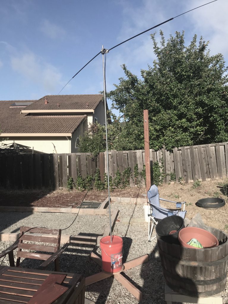
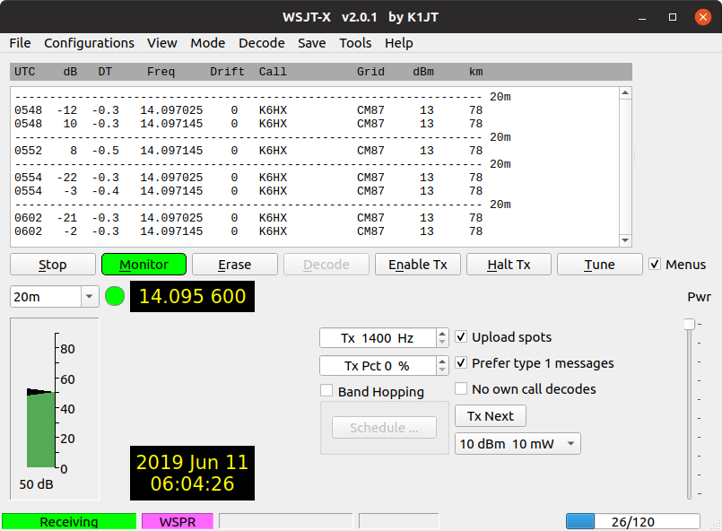
I set it up and home and set it beaconing. I didn’t get the torrent of spots that I had gotten when I had used a similar setup with 5w of power (using my FT-817) but a few minutes later I did get a spot from KA7OEI from DN31, a distance of about 933 km.

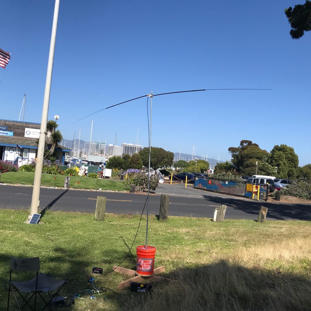
Huzzah! Thought I. I was ready for field day. Mind you, the entire thing was still just a pile of breadboards constructed out of wire. I decided to use my Chinese charge controller and a 20w panel to drive it and to recharge a 7aH lead acid battery. I packed it all up and headed to Emeryville on Field Day.

I’d like to report success, but the fact is that once I got it set up, it was apparent to me (by a lack of blinking lights and LEDs) that it wasn’t working. I wasn’t sure what was wrong, but I had failed to bring my laptop so debugging it in the field seemed like it wasn’t going to happen. After a couple of hours, I decided to pack it in. Sad.

Setup, but disappointingly didn’t generate any RF or even a single spot.

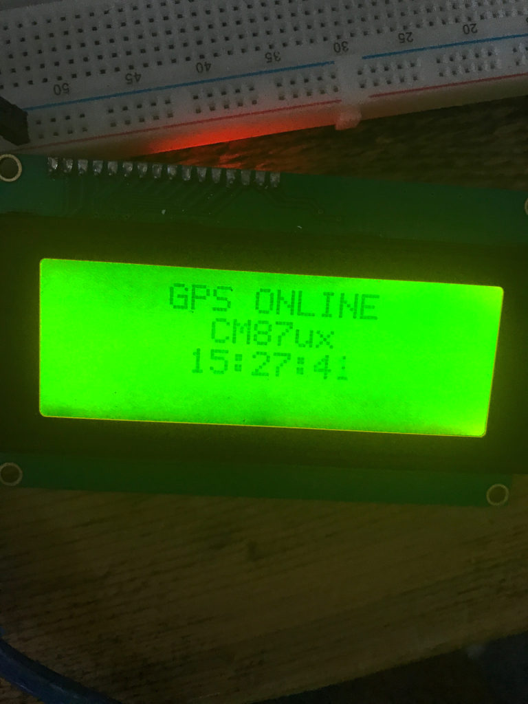
The next day I unloaded it from the car and tested it out. The Arduino and the LCD unit seemed completely dead. I reflashed the code onto a new Arduino Nano, moved it all to a single breadboard, and reset it up in the backyard, and it has been beaconing on 20m, entirely powered by solar since then.

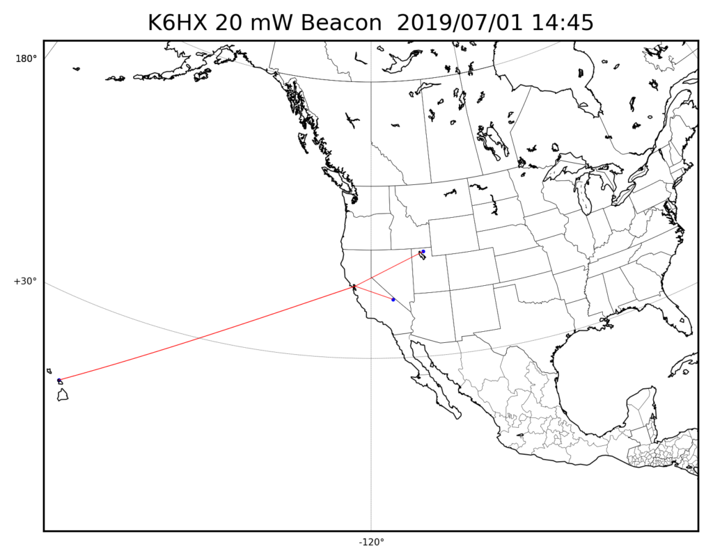
Since then, it has been spotted by 15 unique stations. By far and away the most reliable connection has been to KA7OEI-1, who has heard it 337 times in the last week. ND7M comes in next, with 118 spots. Distance records are pretty much evenly split between AI6VN/KH6 in Hawaii, and WD4ELG in North Carolina.

I made a small map which updates frequently, showing all the spots for the previous 24 hours. You can view that from my home webserver, at least until I get bored with it and take it down. I used the Python matplotlib to generate the maps, this one being an example.

I’ll probably try to get this up more or less permanently, and may add a small RF amplifier to boost its output to around 100mw. I will probably also shift to using an ESP8266 based module so that I can monitor and control the system via WiFi. I’ll update you when I get that going.

Hope you enjoyed.

Shaking off the rust…

July 1, 2019 | My Projects | By: Mark VandeWettering

As part of my attempt to get into woodworking and develop some actual skills, I have been keeping an eye out for what would best be described as “junky piles of rust” at garage and estate sales. I have been updating my twitter feed with pictures and short comments, but I thought it might be fun to include some of what’s been going on here, in a longer format, and in a way that is more permanent and findable once my twitter posts fade into the past.

First of all, about a month ago I found someone selling this old Delta jointer for a good price. It was dusty and dirty, but entirely functional. I’d been looking for a jointer for quite sometime, as I think a jointer and a planer will make all sorts of woodworking more productive and more enjoyable. This one may not look like much, but the bed and fence are actually just dirty and not very rusty, and the planer works, although I think the blades could use a bit of sharpening. The stand is fairly rusty though. I got one quote for having it sand blasted and powder coated, but might still just attack it with my angle grinder and a wire brush. I’m also not fond of the power switch situation. It is basically a wire loop on the rod you see in the back of this picture that flips a power switch. I think I’ll find a way to mount a safety switch with the big paddle “OFF” on the front of the stand so it is easier to turn off and on. It’s also quite heavy, so I might think about figuring out a way to move it around easier.

Last friday, I found a guy selling some Stanley planes, and went to take a trip. I wanted a No. 4 and a No. 5, but ended up coming away with two No. 4s, a No. 5, and a No. 6. They were in what I would call “fair” shape: with a fair amount of surface rust and staining, but with all the parts and no obvious breaks, pitting or damage.

I’ve only started to work on the first of them, the No. 4 on the top which from the looks appeared to be the older of the two No. 4s. A little reading on the web made me believe that it is a Stanley Type 19, made between 1948 and 1961. I disassembled the plane and had a look at the various parts. The sole was perhaps the most interesting part:

As you can see, the bottom was fairly rusty and stained. I thought about using my electrolysis setup to get rid of it, but it was already busy with another project (see below) so I got out some of my trusty Metal Rescue and set it soaking. Four hours later, I pulled it and and gave it a light scrub with a Scotch Bright Pad. The results were really impressive:

There is still a little light staining, but the surface is overall very smooth. The blade and chip breaker had a small amount of rust which was also completely gone after the soak. I still have to clean and polish the nuts and bolts. I did try some Brasso on one of them, which looks like it worked just fine:

I should have the parts all reassembled and ready for sharpening soon. Then it will be onto one of the others. The bottom of the No. 5 is particularly bad, and may have some actual pitting. I’m excited to see how it will turn out.

I passed another garage sale and picked up a rusty Crescent wrench (like, actually made by Crescent) for $.50, along with a rusty chisel. I figured I could practice my sharpening skills on the cheap chisel.

There was only mild rust and some pitting on the wrench, but as a bonus it was frozen and wouldn’t move. I thought I’d give a shot at trying to use electrolysis to both get rid of the rust and see if it would free the mechanism. About fifteen minutes into the treatment, I saw small blobs of grease floating to the top of the bath, and four hours later, the top of the bath was the orange rusty scum that I’ve come to expect. I pulled the wrench out, and all the orange rust was gone, but there was still some scaling, and the black oxide was pretty hard to scrub off. And it was still frozen. So I let it go for another four hours, without much change. I ended up putting a couple drops of 3 in 1 penetrating oil on it, letting it sit for ten minutes, then giving the thumbwheel a couple of gentle taps with punch and a hammer. It yielded fairly quickly, and running it back and forth a couple of times it began to work pretty well. A screw holds the thumbwheel in place. I found a good fitting screwdriver and tried to get it to back out so I could remove the jaw, but it wasn’t cooperating. I left a couple more drops of penetrating oil on it, and an hour later, it came out easily. The jaw, screw, and thumbwheel separated from the main body, as well as a small brass wire ring (a washer?) that I wasn’t expected. I took a wire brush and some degreaser and cleaned these parts, and then let them soak for a bit in some Metal Rescue. I’ll get these back assembled shortly.

Restoring broken tools to working condition makes me feel virtuous. It’s also pretty fun.

Anyway, that’s all the “rust” related activities for the week. Once I get the No. 4 reassembled, I’ll show some more pictures here.

A new beacon is beckoning…

June 12, 2019 | My Projects | By: Mark VandeWettering

I’ve been mostly working in my workshop on various projects related to woodworking, but last week one of my coworkers reminded me that Field Day, the yearly day where radio amateurs take their equipment into parks away from the comfort and ready electrical supply and operate under conditions which are meant to simulate (at least someone) operating under emergency conditions. In the past, I haven’t much paid attention to it, except perhaps to go see what people are up to in several local parks.

This year I thought it might be fun to resurrect some of my past ideas/skills and at least do some minor bits of operating. But I also thought it would be fun to use some of my homebrewing skills to bodge something together as a kind of tech demo and excuse to tinker in the shop.

A decade ago, I went through a phase where I was interested in beacon operations, operating a small, low-powered, automated transmitter that could be heard around the world. This was no doubt inspired by Bill Meara’s chatting about it on his Soldersmoke podcast, and took the form of both QRSS (low speed CW) and WSPR (Weak Signal Propagation Reporter) transmissions. I first started doing WSPR back in 2008 by generating the necessary tones and playing them back through iTunes into my FT-817.

At various times I started homebrewing small transmitters together, but I never really got anything off the bench and into operation.

But I’m hoping to do better between now and Field Day.

Over the years, I’ve accumulated a lot of parts that should make this possible, or even easy. So currently on my desktop I’ve got the following parts:

  • An Arduino Uno. I could use any of a number of other microcontrollers, but the Uno is certainly capable. I may replace it with an Arduino Nano in the final version.
  • An Adafruit SI5351A breakout board. In the past I’ve tinkered around with simple low powered crystal oscillators, but this board is insanely cheap ($8) and can generate three different oscillator signals simulataneously. The board has a great driver written by NT7S that makes it dead easy to control.
  • A cheap GPS module. Ideally, our beacon needs to know where it is and what time it is, and the GPS module can provide both. I’ve had a couple of these in my parts bin, sitting unused, but I soldered some female headers onto the wiring harness and smeared a bunch of hot glue on it to make a crude header, and it worked perfectly.
  • A 4×20 LCD display. I had all sorts of different display technologies available, but this one is larger than most and easy to display.

And… that’s about all you need (other than software) to make a WSPR beacon. So that’s what I did. The program boots, syncs with the GPS and waits for it to get the time and position, and then puts the Maidenhead grid and time on the display:

Bad cell phone picture, but it shows it working…

The program then waits for even numbered minutes to start, and sends the appropriate code sequence. Across my living room, I had my FT-817 setup (without an antenna) and it could easily hear the oscillator running, and it decoded the appropriate message.

Reception from across my living room!

There is still quite a bit of work left to do before Field Day.

  • I need to construct a harmonic filter for the output. I took a quick look at the output, and it was a pretty triangular waveform, definitely not appropriate for sending out over a real antenna, even at the 20mw or so output level it will have.
  • I need to bodge together an antenna. I have a pair of 20m whip antennas. I could use either one as a vertical, or I could use an MFJ-347 that I have in my parts box to construct a mini-whip dipole. Not sure what will be best. That will probably be this weekend’s work.
  • I should get a case to protect it and transport it. Right now it’s a pile breadboard with a bunch of wires hanging off it. I’ll probably just make a little wooden half box to mount the LCD, switches, and connectors, and then just double stick tape everything else.
  • The software still needs some work.

That’s all I have time to write up this morning. Stay tuned for more updates and probably video from Field Day where I show this in operation.

Rust removal by electrolysis: a first attempt

May 29, 2019 | My Projects | By: Mark VandeWettering

Yesterday I wrote up my (successful and positive) results at using the commercial product Evaporust to remove rust from some of my smaller rusty auger bits that I got in a garage sale. Last night I got home late after a trivia competition, but decided to toss together a test for using electrolysis using bits and pieces that I had gathered in anticipation over the last week.

First, warnings. While I consider most of this stuff to be pretty safe, I am not an expert on electrolysis or the risks of doing so. You are encouraged to do your own research on the subject. Electrolysis will release small amounts of hydrogen gas which could be a fire hazard, and it does involve chemistry. Do your own research and stay safe!

First of all, the basics: you need a plastic (or non-conductive) container. I decided to use a clear plastic Steralite container that holds about 1 gallon. It’s small, but I wanted to start small, and it was large enough to hold a couple of small items without trouble.

Next, I needed an electrolyte. Water by itself is a poor conductor of electricity, and you need to change that. The electrolyte that seems universally used is sodium carbonate, or washing soda. This is different than sodium bicarbonate, which we know better as baking soda. I know I’ve seen washing soda at various places, but I’ll be damned if I could find a local place that carries it. As it turns out, according to the web you can convert baking soda into washing soda by heating it. I spread a fresh box of dollar store baking soda onto a glass dish and baked it at 400 degrees F for an hour. The overall texture didn’t change all that much, but it did appear less powdery. I’ve heard it described as “more like sand” which didn’t really match what I saw, but I decided to press forward anyway.

You’ll also need a piece of scrap iron to use as a sacrificial electrode. It’s going to acquire a bunch of rust and gunk in the process, so it doesn’t need to be pretty or nice. I was going to use a scrap of steel strap from my workshop, but then found that lots of people use rebar. For convenience, I stopped by Home Depot and picked up two 1ft lengths for about $1.25 each. One thing you should not use is stainless steel: the chrome in it is not something you want to screw with, it can form all kinds of toxic nastiness. I’ve seen people do this online, but DO NOT DO IT.

I needed some wire to hook it up. I had a scrap of Romex lying around, which has an uninsulated ground wire inside. I stripped it, and pulled two pieces about 18″ long. I wrapped some of the wire around the rebar, making a short loop that I could pass a piece of wood to suspend it in the solution. I did the same thing for my No. 16 auger bit.

Oh, and you need a power supply. Lots of people use manual car battery chargers. I had picked one up from a garage sale a few months ago, but I decided that I could use this as an excuse to pick up a little bench top power supply that would allow me to supply it with carefully regulated power. There is probably no need for this, but it gave me an actual number I could stare at. I ended up buying this one from Amazon for around $50 by Eventek. Using a current limited supply gave me some small measure of safety: if I set the current limit low, if the piece and the scrap electrode did accidently come into contact, the current would be limited and I wouldn’t get a short circuit. (But still, don’t allow the two to come into contact.)

Once I got all this stuff together, it was pretty easy to setup. I wound the wire around the drill bit and rebar, forming a loop so that they would hang suspended in the middle of the container. I filled it with about 1 gallon of water, added 1 tablespoon of my homemade washing soda, hooked up the power supply (important: negative to the piece you are trying to de-rust, positive to the scrap, not the other way around) and set the current limit to be about 1 amp, and turned it on. It stabilized at around 12v, which is precisely what I wanted.

Power supply has the red led on, indicated constant current limited at 0.97 amps.

Immediately I could see bubbles forming around the length of the drill bit. Some cruft began to loosen, seemingly mostly from the rebar (at the bottom below, the drill bit is on the top.)

It’s bubbling, and gunk is coming off. It looks like… SCIENCE!

I snapped a quick video with my cell phone camera to help show the bubbling:

Seemed to be working, so I went back into the house and watched some TV. I came back out a couple of hours later, and was met with this rather disgusting looking sight.

It looks worse than it is. I’m told that if you use graphite rods as your scrap electrodes, you won’t get this sludge, but it is mostly just rust. I decided at this point to reduce the current to just 0.5 amps and let it go overnight. This was from an overabundance of caution more than anything else. At just 0.5 amps, the voltage dropped to about 7v and the bubbling was less vigorous, and I left it until this morning.

Because of the reduced vigor in bubbling, a lot of this sludge had settled out and things appeared pretty calm. The auger bit seemed pretty black, so I thought I’d call this initial run done and fish it out. I unwrapped the wire, and then gave the drill bit a quick rinse. Much like my experiment with Evaporust, the bit seemed to be covered in a bit of black residue, but didn’t have any rust. I tried a bit of scrubbing with a green kitchen pad, and then briefly upgraded to a stiff wire brush to try to remove the remainder. I didn’t work on getting it perfect, just wanted to make sure it was clean. Here is a comparison shot of it compared to one of its rusty mates (the No. 14 from the same box).

I suspect that with a bit more hand work (and a smaller wire brush) I could get most of the black off. The difference in texture between the two is quite startling: the treated bit is very smooth and doesn’t feel rough or porous.

Overall, I consider this a success! So much so, I took the other drill bit and set it going in the goop for the day. Eventually I’ll get all the bits processed.

Given that these bits began their stay in my garage looking like this:

I am pretty happy with the overall results. Either Evaporust or electrolysis seems like an effective way to restore rusted old tools, I can recommend either. The nice thing about Evaporust is that it’s simple and straightforward: you just soak the part until its derusted. The nice thing about electrolysis is that it is probably less expensive to scale to large scale. I’m thinking of using it to restore some old handsaws that I have. Stay tuned.

Rusty skills, and a 3 day weekend in the garage…

May 28, 2019 | My Projects | By: Mark VandeWettering

It is Monday morning, and I’m enjoying my coffee before heading off to work. All in all it was a pretty productive three day weekend, and I thought I write up a quick note about what I got accomplished.

First of all, I got some woodworking in the shop done. I finished constructing the mover dollies that I’m going to put under the shelves in my garage, and got one installed. They work great! When they are all done, I will be able to move, rearrange and more easily access and sort the contents of my shelves, which should help keep that part of the garage both compact and accessible.

I don’t have any pictures of the completed frames, but here they are assembled, just minus finish and the casters. The bottom of each of the plastic shelving units has some protruding plastic pipe that normally a plastic molded foot attaches to. Now, they just drop into the holes in the dolly. I didn’t see any reason to permanently attach them: the fit is tight enough that simple friction and gravity should do the work. Carmen and I put some Thompson Water Seal on them so we could hose them off if they get dusty or dirty. I must admit I could have done a better job of that, but the wood is pretty marginal and we didn’t do a lot of work trying to sand them or get them ready for finish. Meh. It’s shop furniture.

A lawn tool cart, nearly finished.

I also built another cart this weekend. This one was designed to hold all or most of of our lawn tools: rakes, shovels, and the like. We had a pair of the pictured green organizers, which were designed to be bolted to the wall. By themselves, they are too flimsy and have a poor center of balance, so you can’t really make them work as a stand alone holder. So, I designed and built this cart using a couple of 2x4s and basically a full sheet of some scrap CDX 3/4″ plywood that’s been sitting in my garage for the better part of two decades. The picture above shows the basic design. It needs some sanding, paint (Carmen is threatening to make it a bright color) and the casters mounted on the bottom. My original design was going to use the green racks on both sides of the center, but now I’m beginning to think that certain heavier tools like a grub how could be better handled by building a simple bin on one side. I think I’m going to hold off on installing the organizer on one side, and see how the cart overall works out. If I decide to build a bin on the back side, it will probably be about 60% of the height of the separator wall, and will likely just be a front frame with a couple of stretchers.

I’ll have to start designing projects before I start cutting.

Anyway, the last thing was I worked on was the rusty auger bits that I purchased at an estate sale last week.

Ick.

By way of example, here is a reminder of what they look like. These are the largest examples, and show the rust most clearly. There are a couple of things going on here: simple dirt, rust, and I think that they were probably also rubbed down with something like linseed oil which polymerized into a varnish like coating in spots. Yuck. I thought I’d run a couple of experiments to see if I could get them cleaned up.

I took a wire brush to a couple of the smaller specimens. It was pretty good at getting rid of the oily varnish layer and removed a lot of the surface scaly dirt and rust, but the overall look was still pretty rusty.

I’ve been watching YouTube videos, and a lot of them recommend a product called Evaporust for getting rid of surface rust. You basically just soak the piece in Evaporust, them scrub a bit with a pad afterwards, and.. voila. I went and bought a quart ($10) from a nearby auto parts store, found an old quart water bottle with a cap I could sacrifice to the gods of chemistry, and set it to work.

After eight hours of soaking, all the red iron rust is gone, converted to this thin layer of black oxide…

After eight hours of soaking I fished them out. Very nearly all traces of red rust is gone. The parts had a thin layer of black schmutz on them, which mostly came off with a little scrub from some green pads. I snapped the picture above after only the most cursory wipe down. A little additional polishing made them look very nice, if not entirely brand new.

Evaporust gets my thumbs up, except that it’s a little expensive. I will be testing another potentially cheaper method for removing rust, particularly for big parts: electrolysis.

Basically the idea is to submerge the part in a conductive solution, attaching the part to the negative side, and a sacrificial piece of iron or graphite to the positive side, and then apply a current. The advantage of this over Evaporust is that you can scale it up and submerge very large parts for much more modest costs.

I’ve very nearly got that setup, and will likely use some of the larger auger bits (perhaps the No. 16 bit, which is actually fairly bent) as my initial test. I’ll write up my results when I get them done.

Hope you all had a good weekend too!

The hole (whole?) boring business…

May 24, 2019 | My Projects | By: Mark VandeWettering

Acquisition from an estate sale…

This week, I picked up an ancient, decrepit box of rusty auger bits at an estate sale. The label inside refers to 1884 and 1887 patents by the Irwin Auger Company of Wilmington, Ohio, and it appears to be a fairly complete set, albeit in a wooden box which is pretty close to losing all mechanical coherence.

Why, you may ask, am I buying such a crazy thing? I ask myself the very same question. I guess part of it is that I just find old tools to be, well, very interesting as artifacts of what we would today call “Maker Culture”, but which would have simply referred to as “knowing how to do stuff” a century ago. For the modest investment of $10, I get to embark upon a journey not motivated by anything as mundane as “practicality” or “efficiency”, but I get to glimpse a world where wood didn’t come in the shape that you wanted to, and if you wanted to impose your ideas upon it to construct it, you do using tools which today seem quaint, but which used to be fairly common.

What am I going to do with them? Well, that’s a fine question. In the short term, I’ll probably test a couple of different ways to restore them by removing rust, sharpen them, and maybe even work on cleaning and restoring the box that they came in.

Ferrous oxide!

They are, after all, a pretty rusty mess. But other than that, the condition appears fairly good. I’ve been meaning to test two different techniques for rust removal that I’ve seen demonstrated in the my binge watching of restoration videos on YouTube: either using a chemical like Evaporust (actually, using Evaporust) or removing rust with electrolysis.

If I accomplish anything interesting using either, I’ll write it up here, of course.

I really owe all this insanity to Rex Krueger and his YouTube channel. This episode is what lead me to pay $1 for a brace at a garage sale a couple weeks ago, and to pick up this box this week.

The joys of a five minute project…

May 22, 2019 | My Projects | By: Mark VandeWettering

When cleaning the garage a while back, we discovered our old pink “Fight Breast Cancer” edition Roomba. For some reason, we had put it away and hadn’t been using it for years. The battery pack was dead, but a quick order on Amazon had returned it to working order. It happily scurries around the living room, generally making the carpet look a little nicer, and providing some entertainment (or is it anxiety?) for the cats.

But using it in our dining room was a bit problematic. The dining room is about 4″ higher than the living room, separated only by a small step. This old Roomba seems to not have a sufficient sensor package to detect this, and will gleefully head over the cliff, usually getting high-centered as a result and unable to continue. To combat this, Carmen had an elaborate if bulky system of empty cardboard boxes that she could deploy.

But they were big, and bulky. And ugly.

I came home the other day and noted that she had purloined a strip of 1/4″ plywood from my shop. It was roughly 48″ x 10″. She placed it up against the drop off, merely holding it in place with one of the many shoes that we have in our rack in the nearby hall made the Roomba turn away.

She asked if I could make some more.

Well, as it happens, yes I can. Because my shop is (reasonably) ordered now. I was pretty sure I could make some additional strips to match this original one, and span the 10 feet or so of space of this drop off.

I headed toward the garage. Do I have some more 1/4″ ply? But as I am walking through the hall to the garage, I stare over at the side where a picture frame and some leftover Pergo strips have been sitting for years.

And a piece of 1/4″ hardboard.

Nice! I go into the shop with the 1/4″ board, don’t even bother measuring. Just set the rip fence on my little table saw to duplicate the whip, and quickly take off two 48″ strips.

Carmen was watching me, and as I take off my safety glasses begins to talk about how we might store them. I glanced over at my drill press, where a 1 1/2″ hole saw is still chucked after my experiment with creating dollies for the bottom of storage shelf.

Three minutes later, each of the segments has a nice, finger friendly hole in the corner so we can hang these pieces on a hook in the closet when they are not needed.

This is a dumb project. Perhaps even pointless. But I am taking pleasure in the notion that something which is this simple and dumb could be accomplished so simply and with so little planning.

It’s why I am interested in getting my shop organized in the first place.

More adventures in the shop and around the house.

May 5, 2019 | My Projects | By: Mark VandeWettering

Okay, it’s not really a “shop”. It’s really just my garage. But then again, it’s hardly ever had a car in it in the last two decades, so calling it a garage is perhaps even a bit more of a stretch. But I’m trying to convert it into a place where I don’t mind spending time and have the tools and space necessary to accomplish some kinds of “making” that I haven’t done before and which can’t really be done inside the house proper.

Carmen and I began the day out back with a simple chore: laying down landscaping cloth and mulch in the small flower bed just in front of our retaining wall. For those of you who weren’t talking to me during the incredibly annoying construction process that was the retaining wall, I had the old rotting redwood retaining wall replaced with a properly engineered concrete retaining wall, with new drainage. While we were at it, we started on “zero-scaping” the backyeard, which in the area of our patio mostly meant replacing it with gravel and even more changes to the drainage. That process ultimately was good, but it was mentally exhausting, and we haven’t really done much with the space since last year. As the result, we got a fair amount of weeds and the like growing up through the gravel. Over the last couple of weeks, we’ve tidied that up and sprayed, and got the grass that grows up on our hills trimmed back to comply with fire regulations.

But it’s about time that we got some low improvements going. Over the last week or so, we’ve pressure washed the (rather ugly) concrete patio so it is at least cleaner, and we thought that we should fill the bed which sits in front of the flower bed with some groundscaping cloth and mulch.

When we began this morning, we had this:


And with an hour or so of work, we transitioned into this.

I tilled the area a small bit (mostly in the corner) and raked the debris out and generally cleaned up the ground, and then laid down a roll of cloth and piled out six bags of new mulch. It still needs a lot of work, but it was what I had planned for the day, so I can’t really be unhappy with it.

Then, off to the shop! Carmen had done a fair amount of cleaning herself yesterday, so we had some more square footage to move around in. We are getting to the point where organizing the four 36″ x 24″ plastic shelving units on one side of the shop has risen in my priorities. They are big, and seem to collect an annoying level of junk, none of which is easy to organize or clean because out of necessity, they are too close to one another. But a few weeks ago, I saw this workspace hack done by Fran Blanche:

She basically took a simple mover’s dolly which you can get pretty inexpensively from Harbor Freight, and adapted it to mount underneath the shelving unit that she had. I thought this was a cool idea. But the shelving units that I’m using are a bit bigger than hers. The larger dolly from Harbor Freight is 30″x18″, and my shelves are 36″x24″, which means I’d have to split it along both dimensions. That doesn’t seem right. In pondering it, I have a new solution. It involves just 2 pieces of 2×4 and four inexpensive casters, and I’ll be writing that up when I test out the idea.

But I did have one smaller metal shelving unit which we 12″x30″, and I thought it would be possible to adapt it with just a couple of 2×4 additions. So, I gave it a whirl, and it worked great.

This shelving unit used to sit next to my drill press and gathered all sorts of junk. But now I can easily move it around, or spin it either to sit flush against the wall, or perpendicular to it. I can even roll it across the garage, load stuff onto it or off of it, and then roll it back. Nice! I think that when my other shelving units are on wheels, I’ll really enjoy them as well.

That’s my weekend so far. I might spend some time working on Carmen’s potting bench tonight, which will be great to put behind me so I can then work on a better stand for the drill press.

Have a good one!

I can delay the simplest tasks with endless questions…

May 1, 2019 | My Projects | By: Mark VandeWettering

Cheap fencing boards, after Carmen hit them with the sander.

So, last night I didn’t actually get any woodworking done. Carmen actually did more than I did: she took the orbital sander to some (very rough) and cheap fence material that I’m going to use for the slats on the shelving and cleaned them up. They looked much nicer after this process. At just about $1.75 apiece, they are actually kind of nice cheap material for this kind of project. I think I need six of them to complete the two shelves for my garden potting bench, which means I actually am one short. I’ll have to go back and get a few more (having extras will probably mean I can do a couple more projects).

A frame ready for glue and screws. But I’m not ready…

But I had left the scene on the right atop my rolling utility table. I had cut and trimmed the 2x4s for the top and bottom frames, and test fitted them with some of my 36″ clamps holding them roughly in place. I laid my smaller carpenter’s square inside, and the angles seemed pretty square. Measuring opposite diagonals showed a difference of about 1/8″. That isn’t so great, but neither is it especially worrying. It is, after all just going to be a potting bench, it will hardly matter at all. But it got me thinking about the tolerances, and just how much a deflection from right angles such a difference makes. So, instead of making more sawdust or boring holes, I started doing math.

My table is nominally 33″ x 24″ in size. If all the angles were perfect, you could use the Pythagorean theorem to figure out what the diagonal should be, and you come up with the value of something like 40.8″ But what if the measured diagonal isn’t 40.8″? How much of an angular difference of (say) 0.1″ make?

For that, I had to dust off the Law of Cosines. This is the generalization of the Pythagorean theorem. It is usually written as $$ c^2 = a^2 + b^2 – 2 * a b \cos{C}$$. Let’s say that my diagonal is actually just 40.7″ instead of 40.8″. Using that equation we can solve for the angle C, and if you have your handy scientific calculator around, you can find that the angle would be about 89.69°. (This is actually remarkably close to the accuracy of the cross cut sled that I made a week ago, but which I didn’t use at all on this project. Pure coincidence.)

It’s mocking me.

So, after doing this little bit of math, I thought I’d go back out to the workshop and get something done. So I went out, and stared at this corner for a while. You see, I have a couple of options here, having to do with how I could fasten these corners together. I’m not at the stage where mortising, tenons, dowels or even lap joints are on the table. I was basically trying to decide between two very simple options:

  • I could simply pre-drill and sink two 2 1/2″ deck screws in through the face board and into the end grain of the side rail. Or…
  • I could use my pocket hole jig, and put two Kreg screws in from the side frame and into the face frame.
    • For bonus points, do I want to put the Kreg screws in from the outside of the frame, or from the inside.

(I will of course use glue as well. I have my bottle of Tightbond II ready.)

This simple question actually seemed to have a few dimensions to it, which of course left me ponding thoughtfully like Hamlet, asking “to screw into end grain, or not to screw into end grain. That is the question.”

Frankly, none of this really matters for this project. Either technique is likely to work. It’s not like my potting benchis going to hold back flood waters or hold up a roof. Indeed, the way these frames are oriented, the loads will almost certainly be unchallenging.

But it got me thinking: what principles could guide this choice?

The obvious thing to think about is the strength of the joint. So, which is stronger: a glued/screwed butt joint, or one which is glued and screwed with Kreg screws?

I did a little bit of online research, and the answer is… well… in an hour or so, unresolved to my satisfaction.

The obvious argument against the butt joint is that you are screwing into the end grain of the piece, whereas with the pocket screws, you are screwing into the side grain. Indeed, most people would say that screwing into end grain is a big no no. Wood is not isotropic, and forcing a screw into the end grain is like forcing a wedge in between the wood fibers and likely to induce a split. Thus, if you are screwing into end grain, you should always predrill so that the screw generates less force in a direction perpendicular to the screwing direction. I found this excellent explanation that I found helpful and encourage you to read.

If you read and understand this, then you understand a bit of why the engineering of pocket screws are the way they are: they allow you to not screw into the end grain. By starting in the side and burying themselves into the face, they allow most of the screw to be buried in the cross grain, where the holding power is much better and where pre-drilling is not only unnecessary, but is in fact undesirable: screws hold better in cross grain without a pilot hole.

Further scrounging revealed this page on whether the pockets should go on the inside or outside of the frame. The simple answer is perhaps the obvious one: you want the screw to be heading into the biggest part of the board, which means that you should start from the outside. It is also usually easier to clamp the piece together that way. But… well… that can be cosmetically less desirable. Of course depending on the size of your project, it may be difficult or even impossible to drive the screw in from the inside.

In other words, it’s all trade offs.

So, in the end I didn’t even make one hole in my project. I spent all the time thinking. But in a way that’s great. I want to gain more experience wood working, but since I’m relying on self-teaching, I have to spend time thinking and watching and pondering the possibilities.

Tonight, it’s likely I’ll put the frames together with pocket screws, but I can do so with a bit more confidence and understanding. And that is good.

I’ve also spent some time pondering how I am going to lay out the slats on the top, but I’ll save that for next time.

Monday night sawdust creation…

April 29, 2019 | My Projects | By: Mark VandeWettering

I got home from work today, and decided that the best way to lower my stress level was to go into the garage and make something. I didn’t really have a project in mind. I’ve been pondering making a drill press table and have been thinking about a couple of design options, some of which I mocked up over the weekend in Fusion 360. The inspiration was this really simple base that I found in one of my many sessions of binge YouTube watching:

By modeling this in Fusion 360, I could easily use parametric design to adjust the top size and angle, as well as the height of the shelf, and it would calculate all the odd lengths to reproduce it. But this still has a couple of things in my head that I needed to think about, and I didn’t feel like thinking that hard.

I could have probably started on this simpler design for a drill press stand:

But I don’t need two drill press stands. I was also thinking about making a stand for my combination belt/disk sander, but I wanted to think about that some more too.

This was a stool. The garden table will be bigger, and have a lower shelf, but has all the same joints.

So, I settled on a project that I told Carmen I’d do: a simple little potting stand for use on our (freshly weeded) backyard. We guessed at the dimensions, which were a top at about 36″ high, and about 33″x24″. I had enough 2×4 stock on hand to build the two frames and the legs. The goal is not to make anything fancy: it will consist of a top frame and a bottom frame, covered in some cheap fence boards for the top. In fact, it’s almost exactly the same design as the simple garden stool that I did a few days ago, except that instead of just having a top frame, it has a shelf frame as well. I also decided that I’d spend a little time ripping the sides off the 2x4s, taking 1/4″ off each so that the final stock is a little straighter and has nice crisp edges. I also think that using Kreg pocket screws to build the top is probably a waste: I plan to just use butt joints and deck screws and glue.

Bailey inspects the garden stool after Carmen painted it. I think he approves.

Anyway, there are still some details about the assembly that I have to work through, but I spent an hour cutting all the parts to length and ripping the sides, and then some more time cleaning off my assembly table and doing other small bits of tidying.

I think the frames will be glued and screwed together, but that I’ll attach the legs with carriage bolts so that if we ever want to disassemble the table, I could just remove the bolts and stack everything down into a small space.

I was too lazy to take any pictures tonight, and besides, there isn’t anything actually exciting: I just have a pile of lengths of wood on my desk. Tomorrow I’ll glue and assemble the frames, and then cut the slats for the top and the bottom shelf, and it will begin to resemble a bench.

The good thing is that I feel kind of relaxed now. It was a peaceful time in the shop.

Catch you all later.

Update on tool caddy, with a few lessons learned on designing and order of operations

April 25, 2019 | My Projects | By: Mark VandeWettering

Got home from work after seven last night, so didn’t have a ton of time in the workshop. I was also impatient to actually get the parts for my tool caddy actually glued up, so I worked rather more quickly than I should have. I taped the edges, spread some glue, rolled up the sides into shape, checked for square (still hardly perfect) and then shot some pin nails in the side. I then also routed a shallow dado in the bottom for the center divider to fit in, cut it to size, and then later glued and tacked it in. I then spread glue along the bottom and sides of the center divider, centered it in and shot some additional pin nails to hold it in place.

Here is my original, standing along side its inspiration. It’s not a slavish copy: the center divider is slightly taller, the slot a bit narrower (the ends match the 1″ Forstner bit that I had) and I haven’t gotten in the dividers. I’m also debating whether I really want to add the little side areas. I do find them convenient to hold a pencil and my box cutters, but I’m not sure they are essential.

So, what are my lessons learned thus far?

This is the first time that I’ve worked with 1/4″ plywood and pin nails, and it shows. My ability to drive a 1″ pin nail at right angles to a face and into the narrow edge of 1/4″ plywood without having it drift out the sides is… well… it happened a fair amount. I actually wanted to use shorter nails which would help, but my local Home Depot didn’t seem to have many 23 gauge pin nails in stock. The rule that I learned is slow down and be careful, but even then, it seems like had a few wander out the face.

In fact, slowing down in general seems to be a good rule. I wanted to bat this thing out, but I frankly would do a better job and would learn more if I just sat back and really thought about the project and developed a plan. I have to balance this out with my natural (and helpful) desire to just finish things so I can go on to the next thing. And I still must recognize that some of that will simply come with more experience.

But mostly I think that adopting a better, more careful plan on exactly how to construct the project would be helpful. As an example, my order of construction on this project would be roughly:

  • Cut sides, middle and bottom. I did this on the table saw, so they were all ripped to the same width.
  • Cross cut the pieces to length using my cross cut sled.
  • Assemble the shell with pin nails and glue.
  • Slot the center of the bottom with a 1/4″ router bit set to make a shallow dado, and then glue and attach the bottom.
  • Apply glue to the center and slide it into place, pinning in place with some pin nails.
  • Measure and cut some dividers, apply glue and hold in place with pin nails. (yet to be done.)

It’s not a bad plan, really and mostly worked. I rushed some steps so some of them aren’t done brilliantly, so a couple of the glue joints are probably weak (mostly from lack of clamping pressure). But the real mistake was building the project from the outside in, instead of the inside out. Were I to try this project again (and I might), I would likely do it from the inside out. This would mean an order of operation which would be closer to:

  • Cut the pieces again. But instead of relying on butt joints, consider using shallow dadoes, not just for additional gluing area/strength, but to register parts together during assembly.
  • Begin with the bottom and the middle divider. Route the dado in the bottom to hold the divider, as well as possibly shallow slots for the cross dividers. Attaching the dividers to the center will be easy before the entire things become wrapped in the sides.
  • I noticed that the interior dividers in the original are actually made out of 1/2″, not 1/4″ plywood. The heavier material could be used structurally to ensure the middle is set at right angles and is sturdy.
  • After the center is fit, then construct the outer case. You could even apply either end first, glue clamp and dry, and then apply the sides. This gives you additional opportunity to double check for square.
  • You could also consider adding additional reinforcing dadoes in the faces, although to do so in 1/4″ plywood would likely require measuring and care to a degree which I would apparently consider challenging.

Maybe the details of my “new plan” aren’t right. Maybe they are excessively fussy. After all, I am just building a tool caddy, it doesn’t have to be a model of jointing perfection to be useful. But I am trying to use projects like this to build skills and train my mind and hands to work more consistently and carefully, and I find the kind of problem solving that I’m exercising here to be helpful (and pleasurable).

It’s likely that I’ll just cut some dividers out of 1/2″ plywood (easier to tack in place) and glue them in, rub some boiled linseed oil on the whole thing, and call it done. But I think I’ve learned some lessons, and whatever my next project is, I’ll try to carry some of the lessons forward.

Other simple lessons:

  • I did take some time to measure the accuracy of my cross cut sled. It’s about 0.27 degrees off, making cuts which lean a little to the left. 0.27 degrees doesn’t sound like much, but in an 8″ wide board that’s the better part of a full mm, which is pretty easy to see and pretty obvious when you lay a square against it. I used that sled here to cut my sides, and while the overall thing went together fairly well, it’s still not to my satisfaction. I think that version #2 of my cross cut sled is likely a project I’ll try sooner, rather than later.
  • I didn’t take enough care to get the slot for the center divider actually centered in the base. If I were to do it again I’d take more care, and were I to add matching dadoes for the two ends, I’d likely choose an order of operation where I first slotted the piece, then cut them to size to make sure the dadoes all lined up precisely.
  • More clamps. I also think some 1-2-3 blocks would likely help me get things lined up properly.

Anyway, that’s enough for now. I’m likely to spend some time in the shop this weekend, if it doesn’t get too hot. Yesterday, temperatures reached about 85, which I don’t find comfortable. I had Carmen open up the shop doors, which helped a bit, and it was probably only 80 when I did the bulk of the work, but if I can do some work on Saturday morning, I’ll probably find it more comfortable.

Hope you all are having a good day.

Building a tool caddy…

April 24, 2019 | My Projects | By: Mark VandeWettering

A few weeks ago I was at a garage sale, and picked up a few old tools for just a few bucks. One of the things I got was a little tool caddy for $1. It basically is a box with a central handle, constructed from 1/4″ plywood and divided into a number of compartments.

In the weeks since, I’ve found it to be remarkably handy. I can load it with tools like hammers, wrenches, tape measures, rulers, my coping saw, my box cutter, and whatever, and then move them all from my workbench to my desk to my floor.

As it happens, I had a quarter of a sheet of 1/4″ plywood lying around and I thought it might be fun to make another one, basically copying the same design. I thought that this one might be good to hold various painting supplies, like brushes, cans of spray paint, masking tape and the like, but the general design is sufficiently versatile that I thought it might be useful regardless.

And, I’m trying to build skills and familiarity with using my tools.

So, last night I ripped most of the pieces, used my (imperfect) cross cut sled to cut them to size, and duct taped the basic design together, copying (not slavishly) most of the dimensions from my garage sale find. Sadly, I don’t have a picture of the original, but here’s the basic layout of the existing one.

Held together (just temporarily) with duct tape…

Tonight, with a little bit of luck, I hope to get the sides glued and pin nailed together, and then cut the bottom to fit. I may route a 1/4″ slot to allow the middle divider slip in. Then, with any luck tomorrow I’ll measure and fit some dividers, and finish up with some finishing.

This isn’t really amazing woodworking I know, but it is a baby step along the way of gaining some basic competency. I could definitely use practice in just the basics of measuring, cutting, and assembling boxes. It is also a project that I can easily complete in small chunks of 30 minutes, which means I can get them done during the week.

Stay tuned for a final update later this week.

My first real table saw jig: a cross cut sled

April 21, 2019 | My Projects | By: Mark VandeWettering

After yesterday’s success in building a little garden stool, I wanted to get back into the garage to do a little more woodworking. Sadly, today was the last day of my “staycation”, and I still had quite a few chores. I spent part of the afternoon breaking out the pressure washer to clean the mold and lichen off our sidewalk leading to our front door, and that took a fair amount of time (although it looks quite a bit better).

So, it was after seven before I got into the workshop. And I decided that I wanted to finish a jig that I had started awhile ago: a simple little cross cut jig for my table saw. I had cut most of the pieces for it days ago, but it had been sitting in a pile on my assembly table, mocking me.

I was chickening out. The thing about a cross cut sled like this is that you want it to be really accurately set at 90 degrees, so that you can make great repeatable cuts without any fear. And because I’m still a novice, I didn’t have any confidence that I could lay such a thing out.

But, I decided to dive in.

Glue. Screws. Double checking with my framing square and my machinist square.

And, here it is.

Finished!

Okay, but how square was it?

Well, holding a square against the real fence and the blade, it looks pretty square. Unless I look really hard. Then I can see that there might be the tiniest gap at the back of the blade when I hold the square to the right of the slot, and a tiny gap at the close end when I hold it to the left.

My guess is the error is something on the order of half a degree or so. This is okay for most of what I normally do, but it isn’t great for the most critical work. I can quantify the error more carefully (and probably will sometime soon) by using the 5 cut test. I’ll have to prep some 8″ or 10″ pieces of material to make the test. When I do, I’ll report back here.

I’m also thinking about adding a piece of polycarbonate across the top to provide a little extra safety. I am trying to decide if I should bore some holes to mount it, or just fasten it with some mounting tape.

I’ll ponder the various sources of error more carefully over the next few days. But for most pedestrian uses, I suspect it will be entirely adequate, at least for a while.

Anyway, tomorrow I’m back to work in a new role at Pixar which will likely take up more of my time and energy. I’m excited by the new opportunity, but want to try to make sure that I continue to make headway on some of these “outside” tasks. My goal is to try to continue to get some hours in on projects like this mostly by jettisoning more passive and useless activities like watching television. Wish me luck!

How to turn pulling weeds into a wood working project…

April 19, 2019 | My Projects | By: Mark VandeWettering

Okay, after all the drought-ending rain we’ve been having, our yard has turned into a lush jungle of various kinds of weeds. Part of it is just grass which has sprouted above the black landscape cloth in the mulch, but other areas were more or less unimproved since we finished our retaining wall project last year. After a couple of days of actually doing vacation stuff during my vacation, I decided that doing chores was probably something I should get to. So, Carmen and I set to work.

First on my agenda was to weed-whack the worst corner of the back yard, while Carmen set to work on pulling some of the weeds. This plays to both of our strengths: I like to do big things, preferably with power tools, and she is more fastidious and careful in making things look nice. I also don’t mind wading into piles of buggy weeds where a tick or two have been known to hide.

Anyway, after a half and hour or forty minutes, I had gotten the worst of this corner roughly chopped and tilled (sorry, no “before” pictures):

Where once there was a lush patch of thistle and weeds, now, there is mostly dirt…

I then went to check on with Carmen. She had been making some good headway, but wished aloud that she had a low stool that she could sit on while pulling weeds. I empathized with her: I don’t like crawling around on my knees either, and bending over while standing isn’t all that much fun for my lower back.

But then I thought “Hey, I have tools, and some scrap lumber. I could make a nice, sturdy little stool that we could use for this purpose.” And not only that, I could then stop working on the weeding and spend time in the garage using power tools instead!

So, that’s what I did. I spent a little more than an hour cutting up pieces of 2x4s and attaching them with some 2.5″ Deck Screws that I had lying around, and then topped it with some other scrap boards I had lying around. I decided not to glue anything (who has time) but did spend some time pre-drilling and countersinking screws to hold all the pieces together. I didn’t draw up a plan, but I had been thinking about how to make a potting bench, and most of the elements here are the same, just smaller. I just cut six pieces of 2x4s 16″ long and 2 pieces 20″ long. This made the top about 19″x20 when I assembled the frame, and the top is about 16.5″ tall, which was about right to enable us to work at our feet while sitting. Carmen used my newly completed router table to smooth over all the top slats with a 1/4″ roundover, and I eyeballed all the hole locations and screws, trying to get the edges even and the spaces relatively uniform. It’s better than it needs to be.

Here’s the completed (but not yet finished) bench in place in our flower bed.

I haven’t figured out how we should finish bench yet. Carmen I think is fine with just spray painting it. I am tempted just to rub a couple of coats of linseed oil on it and let it be that way. Anyone have any suggestions?

It’s good and strong. I’m a big (okay, I’m fat) guy, and sometimes stuff like this creaks ominously when I sit on it. This seems really, really stable. I have no fear if I chose to jump up and down on it.

And, I managed to spend two hours in the shop woodworking instead of doing more lawnwork! And Carmen even thanked me for it. Double score!

My Dust Collection “Cart”

April 16, 2019 | My Projects | By: Mark VandeWettering

I have been trying to do a bit more wood working in my garage, with the net result that a fine layer of sawdust is settling everywhere. I had started to use my aging Ridgid WD12000 4.5HP 12 gallon wet-dry vac attached to my table saw and my newly finished router table. But just using a vacuum on the outlet port isn’t optimal. The fine dust that these machine tools produce can easily clog vacuum filters. The obvious upgrade is to add a dust separator into the “system”. I did some research on the costs and benefits of using them. While there were some designs for a completely DIY designs, and many expensive “off the shelf” systems you could purchase, I settled on using a cheap, available cyclone based extractor called the Dust Stopper which I could get for about $40 from Home Depot. It is a little plastic “cap” that you can place on top of one of the ubiquitous 5 gallon buckets you can get from the big box stores. Air is sucked in the side, and swirls around, eventually settling into the bucket. The wet-dry vacuum pulls air from the center of the vortex, where it is much less dusty. This results in less dust in the vacuum, which prolongs the life of the filters and the vacuum.

Here is a picture of what the system looks like, from Home Depot’s product page.

Can you spot the problem?

But there is a problem. As you tug the vacuum hose around, cleaning up or attaching it to one tool or another, it is just downright cumbersome. It’s easy to knock over the bucket, since it doesn’t have wheels. And even if you had a separate dolly for the 5 gallon bucket to sit atop, you’d be maneuvering two different items on rollers which were attached together with a stiff but flexible hose. Not fun.

The obvious solution would be to build some kind of cart to hold both items together. Youtuber Steve Ramsey was an early inspiration to me in my quest for woodworking competency, and he details both the problem and his (rather nice) simple solution.

But there were still some problems with his cart. He replaced his old, large shop vac with a smaller unit, but the footprint of the cart is still essentially 2x the footprint of the vacuum alone. My old WD12000 has a lot larger footprint, and would have a correspondingly larger cart. I liked his idea, and wondered if I could do better.

The obvious idea would be to mount them vertically, rather than horizontally. I found a number of very nice designs, some of which were very complicated and included all sorts of storage space and things like hose reels. I’d love to have such a cool cart, but I didn’t want this to be a project in itself. After all, my shop vac is quite old, and could easily give up the ghost any day. I’d hate to invest all that time and effort, only to have to rebuild the cart for a new vacuum.

So, I was looking for a simple solution when I stumbed upon this neat idea from John Builds It on YouTube.

It uses a feature of these Ridgid shop vacs. They wheel around on four feet, each of which are topped by a cylinder that you can use to store the various wands and accessories. John basically used them to hold vertical legs, which then bolted into a platform with a hole cut in the top that the dust extraction bucket could sit in. The entire system rides on the original vacuum, which means that it has no more footprint than the original.

My own version…

Watch John’s video for details of his (much better) build than mine. But here are some details from my own simpler build.

I did some quick measurements. It is about 24″ from the top of the feet to the top of my vacuum cleaner, and I thought it was about 12″ from the bottom of the bucket to the “lip” that will hold it in place. Because I didn’t measure all that carefully, I decided that I needed 4 pieces of 1.5″ schedule 40 PVC, which I said needed to be 38″ long. I also picked up 4 flat endcaps, and four 2″ to 1.5″ reducers similar to the ones specified by John. The idea was that the reducers would fit on the outside of the feet, and then the pipe would fit inside the reducer and rise up above the vacuum, ending in a cap which you then bolt to the platform which was cut from some scraps of 3/4″ plywood I had around. As John explains in his video, you can’t use 2″ PVC for the risers (which might have been a better fit) because the body of the vacuum tapers out slightly, and the verticals won’t be straight. But I discovered when I did a dry fit that the 1 1/2″ Schedule 40 PVC actually was a loose fit inside the cylinders that cap each foot, and was a better fit overall than the reducer was to the outside. I ended up returning the reducers, and just resting the pip inside the foot.

I cut a 19″ square piece of 3/4″ on my table saw, and marked four in the corners of a 14″ square (the measured spacing on the bottom of the vacuum) centered in the top, and bored it for some 1/4″ bolts. I then used my drill press to cut 1/4″ holes in the center of each of the black end caps. I then made a homebrew compass out of a scrap of wood, and marked the circle centered in the middle of the top. A little math showed that the radius was about 5 5/8″, for a diameter of 11.25″. I drew the circle, drilled a starter hole, and then cut out the center with my jig saw. I also rounded the corners, and then used my new router table to smooth over all the edges. I then bolted the endcaps to the top with some 1/4×20 screws that were about 1.5″ long, and held in pace with some stop nuts.

And that’s about it. PVC posts in the foot, caps hold the top of each post, and the bucket drops in. The only unforeseen issue (and additional expense) came when I realized that unlike John’s setup, I had built mine a little too high, so the 36″ section of hose that came with the Dust Stopper wasn’t long enough to reach. I ended up getting a new 7″ section (which is too long, but it’s what was available) and we were done. Actual time spent doing the work (as opposed to going to Home Depot Twice) was about an hour, and I’m slow.

I haven’t fixed the base of the risers into the feet yet. Friction holds them in reasonably well, but I will probably get a small self tapping screw to fasten them more permanently, or maybe just wrap the ends with tape to increase the friction a bit more. But it’s totally workable, and is easy to move around the workshop.

I’m pleased. I’ll be using it for the first time “in anger” tonight when I cut some pieces for a potting bench for my wife.