More on $.99 Christmas lights…

December 6, 2011 | diy, electronics, Merry Christmas | By: Mark VandeWettering

I didn’t have a lot of time to do anything significant tonight, but I wanted to test a few things about this strand of Christmas lights using a multimeter and some simple math.

Recap: there are two strands of LEDs, each wired in parallel. One strand consists of 4 red and 4 yellow LEDS. The other has 4 blue and 3 green LEDs. When powered by two AA alkaline cells, the two strands combine to draw about 40ma of current.

While mulling what I could do with them during the day, it seemed obvious that I could use my ATtiny13 pumpkin circuit to drive the LEDs. While the ATtiny13 is just an 8 pin DIP, it has two PWM outputs, each of which could drive one strand. My pumpkin was powered by 2 AA batteries. The ATtiny13 should have no problem sinking 40ma of current on two pins. Since the LED strands can be powered by just 3V, I could run the entire thing off just the two AAs.

But there is one thing that is a bit wonky: the yellow LEDs. They are really dim compared to the other LEDs. One is sort of okay, but the other three are really feeble. I thought it was possible that maybe the yellows were just feeble (they usually aren’t as bright as good red or green LEDs), but I had another hypothesis: that the forward voltage for those leds was really close to 3v, and they weren’t really conducting properly.

To a first approximation, until the voltage across the diode reaches the forward threshold value, the diode doesn’t conduct. If the yellow LED was barely meeting (or not) meeting its forward voltage, then it’s not passing as much current as the other LEDs. In fact, in this parallel arrangement, it means that the other LEDs are passing more current than you would think (the overall current is still limited by the current limiting resistor in the circuit, but the balance is wrong).

So, I hypothesized that if I raised the voltage perhaps I’d get more even illumination. I hooked up a 5v supply, and… yes! the lights did seem a bit more even, and the yellows, while not exactly blazing, were at least reasonably illuminated. I then hooked up a ammeter to measure the current through the circuit. I knew it would be higher (obviously, since the LEDs were brighter). Indeed, it measured 120ma or so, nearly 3x the current. To keep the same 40ma current, I’d need some additional current limiting resistance. I tried inserting a 220 ohm resistor, and the green and blue strand were nearly completely extinguished, and only the red LEDs of the red/yellow strand were illuminated. Obviously the voltage drop across the resistor was too great to cause the forward voltage of most of the LEDs to conduct.

So, I dusted off a small 200 ohm pot from my junk box, and inserted that. I then tuned the resistance to match the 40 ma of current that we saw at 3v. And, indeed, while the current draw was the same, the illumination was quite a bit more even: the yellow LEDs were quite reasonable.

This suggests that maybe the right thing to do is to drive the LEDs with a bit higher voltage. I’m now thinking that I’ll power the ATtiny and the LEDs with a 9v battery into a 5v regulator. Since the capacity of the 9v battery is a bit lower, it won’t last as long, and we are wasting more energy in the current limiting resistor (I need to add about 47 ohms of resistance to lower the current draw to just 40ma) but I’ll get better illumination.

We’ll see how this works when I get it on the breadboard.

Upcoming Total Lunar Eclipse

December 6, 2011 | Amateur Science, Astronomy | By: Mark VandeWettering

Yep, there is an upcoming total lunar eclipse this Saturday, on the morning of Dec 10. It will be the last total lunar eclipse visible from San Francisco until April of 2014, so I think I’ll be trying to get up and see if I can view it and take some snapshots. From San Francisco, will enter the penumbra at 3:34 local time. You should start seeing it enter partial eclipse around 4:46, and it will begin totality around 6:06 (at only 12 degrees of altitude). Totality ends around 6:57, with the moon at about 3 degrees altitude.

I’ll probably get out my aircraft spotting binocs, and try some ghetto “through the eyepiece” photography. Stay tuned.

“Sub Micro” R/C Blimp

December 6, 2011 | Link of the Day | By: Mark VandeWettering

I’ve been a fascinated observer of indoor model airplanes for years, so this little RC controlled blimp strikes me as one of the most awesome things I’ve seen in a while. It’s just a 10g payload, suspended by an ordinary 14″ balloon filled with helium. Very cool.

MAKE | How-To: “Sub Micro” R/C Blimp


Correction: Schematic for $.99 Christmas Lights

December 6, 2011 | electronics | By: Mark VandeWettering

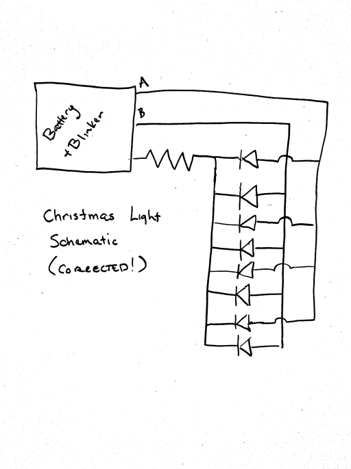
I was in a hurry yesterday, and didn’t draw the LED connections in my schematic for the $.99 Christmas lights properly. Mike pointed it out to me on twitter, so I thought I’d post a corrected version of the schematic. I’ve also updated the schematic in the original post, so no one will be led astray by haste and carelessness.

A Blast from the Past: The Cinnamon Bear

December 6, 2011 | Merry Christmas | By: Mark VandeWettering

When I was a kid, my brother and I used to listen to old time radio shows quite a bit. During the Christmas season, KEX 1190 in Portland would play episodes of radio serial The Cinnamon Bear. The program was originally suppose to air six days a week starting just after Thanksgiving and culminating on Christmas Eve. To this day, whenever I hear the theme, I smile and get a bit nostalgic. If you haven’t heard it before, set your clock back a few decades and give it a try, maybe with your kids or grand kids.

Here’s all the episodes.

Dissecting a set of $.99 battery powered Christmas lights…

December 5, 2011 | Arduino, Arts and Crafts, electronics | By: Mark VandeWettering

I was over at the CVS repository today, and saw that they had some small strings of fifteen LED Christmas lights on sale for a paltry $.99 (if you used your CVS discount card). That was simply too much to resist, so I got a couple of strings, and thought that I would use them for a Christmas related electronics project of some sort.

And, of course, it provides a reason to test your basic electronics knowledge as well. (Forgive my more technologically saavy readers, this is gonna be pretty basic, but I found it fun to go through the mental exercise).

First of all, here are photos of the box they came in, just so we are all on the same page:

When you pop them open, you’ll find a small greenish plastic box that holds the batteries, and a string of fifteen LEDs wired into it with green wire. The box has a small switch on it, which if you stare at you’ll see has both an OFF and an ON position, but it can also be set half way to enable a blinking function. Popping two batteries into the case and flipping the switch had the desired effect: Christmas lights!

So, I started staring at them. There are three wires coming out of the battery box. Each LED appears to have five wires operating in its vicinity. One bypasses the LED, and four other wires sprout from each LED (except for the very last one on the string, which just has two connections. A few minutes of thinking reveals that the LEDS must be wired in parallel, with a circuit that looks very much like this:

Ed. note: Mike pointed out that the original schematic was in error. This has been updated.

The lines labelled A and B are just two power lines: each carries power to half of the LEDs. In the “blink” mode, power is applied to only half of the LEDs at a time. Staring inside the box, it appears that there are two discrete plastic cased transistors wired together: my guess is that they are a classic multivibrator circuit. I’ll verify that later.

Okay, enough of boring reality, let’s try to get to the exciting math.

First of all, the package says that we can get “120 hours or more” from one (presumably) set of alkaline batteries. That seems like excellent battery life, but how realistic is it?

First of all, how much power is in a pair of AA alkalines? Wikipedia says we have about 1800-2600 mAh. I bought some cheap AAs from CVS, so let’s say we are in the middle of the range, about 2200 mAh. Naively, to last 120 hours, the current draw can only be 2200 / 120 or about 18ma (this isn’t quite right, but it’s close) which works out to about 1.2 ma of current per LED (did I mention that the LEDs are wired in parallel?). The total power consumed is about 50mw. If we assume the voltage drop from the LEDs is around 2 volts, we need we need to have a series resistance of about 1 v / 18ma or about 55 ohms. It can be a tiny one, since the power consumed is very small.

All this presumes that they were all in parallel. In reality only half the current flows in each of the A and B circuits, so in blink mode, I suspect the power consumed will be cut by one half (ignoring the power consumed by the multivibrator, which should be very low).

But here’s the good thing! The current draw is low enough that it should be possible to power these lights directly from an Arduino, without any additional switching transistors or the like. My intention is to power each of the two strands with a PWM signal, to allow independent fading and glowing.

But I don’t trust my math enough (nor the specified 120 hour life) to just hook this up randomly, so I’ll be doing a little dissection when I get home tonight, to verify that my calculations are roughly correct. Stay tuned!

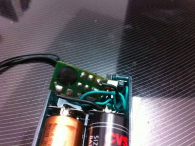
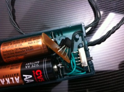
Addendum: I took a closer look at the tiny circuit board inside the battery case, and was somewhat surprised to see its inner workings hidden under a blob of epoxy. Two driver transistors do appear on the top side. As far as I can tell, no caps or inductors are visible anywhere:

Addendum2: Last night I put my multimeter in series with the batteries in this circuit, and measured a current draw of 40 milliamps in its “steady”, non-blinking mode. That means that the 120 hours on two AAs quoted on the box is likely a fiction, a life of more like 55 hours would seem to be more likely. In blinking mode, the current draw seemed to vary between 20ma and 30ma, but my meter wasn’t able to integrate the current to a stable value.

I’m thinking that I’ll resurrect the circuit that I used for my ATtiny13 powered pumpkin to drive these LEDs. The ATtiny13 has two PWM channels, which could be used to drive the two LED channels separately, allowing some cool color fading effects. I could probably even salvage the case to hold the batteries. Stay tuned.

How to make a CheerLights controller with Arduino and ioBridge

December 3, 2011 | Arduino | By: Mark VandeWettering

As the holiday approaches, it seems like making some kind of blinkenlights project would allow some fun hacking, but also be within the spirit of the holiday. I encountered the idea of “CheerLights” during my morning surfing. The basic idea is to create a global network of colored Christmas lights, all of which change color simultaneously as they receive update notices via the Internet/twitter.

How to make a CheerLights controller with Arduino and ioBridge

The project makes use of GE Color Effects lights, which are cool because they are individually addressable RGB leds on a single control bus. I don’t think this project really makes adequate use of that feature, but it’s still pretty cool. The author uses an ioBridge (which he is the creator of) which seems like a very cool gadget, but which is pretty expensive ($120). I could probably write a little gateway between my home server and the Arduino via Xbee, which would be quite a bit cheaper.

Pretty neat idea though, and getting me thinking of a Christmas project…

How to lose $2400 in 24 seconds… with a story of my own

December 2, 2011 | My Stories | By: Mark VandeWettering

We have a bunch of photography enthusiasts where I work, and on Friday it is common for people to exchange their photographs and photography-related stories on a local email alias. Today, someone posted a link to this rather tragic video, which reminded me of a story. Go ahead, watch the video.

how to lose $2400 in 24 seconds from Kurtis Hough on Vimeo.

Okay, now the story. It starts somewhat sadly. My mother Beverly suffered a pretty serious stroke in her early fifties. In those early days, she had a lot of problems: with her vision, with her balance, and with periodic seizures. Not a very fun time for her, or for the people who cared for her, and about her. A couple of years later, I started dating my wife Carmen. It was near the holidays (if memory serves) and I decided to take Adam (our son) and her to go visit Mom near the holidays. At that time, she was walking, and we decided on a drive to the Oregon Coast to stretch our legs and enjoy ourselves. With all her hospitalization, she hadn’t been to the beach (which she loved) in several years, and the prospect made her happy.

Here is the thing about the Oregon Coast, particularly in the winter. You have to be a bit careful, because the waves can seem very peaceful and well behaved, but can suddenly go rogue and you’ll find one running a good twenty yards or more further up the beach than you expect. Thus, my Mom always warned me to not turn my back on the ocean: be aware of your surroundings.

Of course, when your mother who has had a stroke is on the beach, your attention isn’t on the waves, it’s on her. And of course that allows the ocean to sneak up behind you.

We were walking along in the moist area of sand where the lapping waves will occasionally cool your feet, and chatting and talking. Adam was running around (I think he was about 11) and having a great time, when I realized something was about to go wrong. A much larger swell was forming and was already too near to avoid. When it contacted us, it was above my waist, a good 4 feet tall. I managed to remain upright, but Mom was knocked off her feet and was floating with the wave (at first somewhat inland, but as the wave quickly reversed itself and began pouring back out to see, she floated toward Japan).

Adam was a hero. He had regained his feat and had reached my Mom pretty much as quickly as I did. We got her back on her feat, and made sure she wasn’t hurt.

She wasn’t. She was laughing. Harder than I had heard her laugh in a great while.

When she recounted this adventure later, she said that until then, she had thought that maybe she wouldn’t have any adventures anymore: that the stroke had taken those away from her. After nearly doing a solo crossing of the Pacific, she decided that if she was healthy enough for that to happen, perhaps there were still some adventures (and joys) to be had.

She didn’t do a lot more ocean voyaging, but she told stories. She painted. She quilted. She made her children laugh. She made her grand children laugh. She even got to see great-grandchildren. She talked to me a lot about cooking. Over the last couple years, her condition got a lot worse. She passed away in July. I miss her.

Losing $2400 in camera equipment seems bad, but I nearly lost my mother. But that’s the strange thing: by almost losing her, I got her back, at least for a decade. I’m glad she found the courage to struggle on, both for her sake and for ours.

For that reason, big waves just don’t seem that tragic to me. 🙂

The art of capacitive touch sensing

November 28, 2011 | Arduino, electronics | By: Mark VandeWettering

I didn’t get a lot of electronics hacking done, but I found myself again playing with capacitive sensing. I found this interesting article on the EE Times website:

The art of capacitive touch sensing

It also pointed me at the following pretty cool Youtube! vid by the folks at Nerdkits:


My experimentation thus far has been mostly confined to using the CapSense library for the Arduino. This library is pretty simple to use, but it has a number of quirks that make it somewhat cumbersome for the uses that I had for it. I’m currently working on a “better” (for my purposes) version. Stay tuned.

The Sparkfun Serial LCD

November 24, 2011 | Arduino, electronics | By: Mark VandeWettering

I was driving around various Silicon Valley electronics and surplus stores (like HSC and Anchor Electronics) and decided to stop in at Microcenter. I remembered that they supposedly were beginning to stock items from Sparkfun and the Maker Shed. And, indeed they do! I found a Serial LCD module from Sparkfun that I thought might be fun to have, so I got one:


A couple of quick caveats though:

  • The module has absolutely no documentation in the box. A quick bit of searching revealed the datasheet for the device, and that was helpful (although not the clearest that I’ve seen). If you are familiar with HD44780 devices, you’ll have no problems.
  • The pigtail they ship with it connects to the JST connector, and uses stranded wire. Not the best thing to plug into breadboards and the like. I soldered some female headers onto the unpopulated connector, and that worked out better.
  • It doesn’t appear that you can load custom characters over the serial interface like you can with the traditional interface. Bummer.

Still, it was dead easy. If you want a simple module to do some simple display tasks with only three wires, it works just fine.

Apologies for slow website this morning…

November 21, 2011 | Announcements | By: Mark VandeWettering

You might be experiencing slow response to my website this morning. I think it is merely the perils of using inexpensive shared hosting, but I’ve filed a support ticket and hope that it will get resolved shortly. I appreciate your attention, and hope you will persevere in reading, even if the site seems a bit slow.

I can’t complain too much: my website costs me about two lattes a month to run, which means that I don’t need to annoy anyone with advertising and the like to provide it for you. But that being said, I would like my website to run smoothly and quickly for my users. Anybody have any good, cheap and reliable hosting that would be appropriate for running a website that sees 500 or so visitors a day? What’s this I hear about cumulous computing?

Diode temperature sensor update…

November 21, 2011 | Arduino | By: Mark VandeWettering

Lee mentioned that the there was a way to change the analog reference used on the analog inputs to the Atmel AVR to an internally generated 1.1V, which would give me a lot greater resolution (about little over 1mV per step). Indeed, a little quick searching yielded that it was not only true, but dead simple: the Arduino provides an “analogReference” call. If you simply call it in your setup() routine with the argument INTERNAL, you’ll get a 1.1V reference.

To test it out, I did another run, pretty much the same as before, but illustrating the values read after changing to the internal 1.1V reference. Again, I began with the diode in air, then pinched it, released it, pinched it, then released it, then placed it next to a cold can of Diet Coke I had sitting next to me.

Seemed to work pretty well!

Kragen mentioned that the Atmel also had in internal temperature sensor as well. Indeed, it appears that you can simply do an analogRead(8) to access an internal “virtual pin” that links to an internal temperature sensing node. (On the Arduino Mega boards, the pin will be a different one) Read about it more here. I’m currently just using an old ATMega168 which doesn’t seem to have that capability, so I haven’t tested it. It appears that the sensor is noisy and uncalibrated, but it might be useful in some applications. When I dust off one of my more recent boards, I’ll give it a try.

Okay, time for breakfast.

Using a 1N4148 diode as temperature sensor…

November 21, 2011 | Arduino, electronics | By: Mark VandeWettering

I had an application where I wanted to detect temperature. No big deal, lots of good temperature sensors exist. But of course, I don’t have any of those. Rather than order something from sparkfun, I thought I’d just try to see what I could do with the stuff I had on hand. What I had on hand was about 100 1N4148 diodes that I got for about a penny a piece.

The idea is that the forward voltage of diodes is temperature dependent. For every degree Celcius the diode increases, the forward voltage should drop by 2mV. So, I decided to test this idea. I configured the analog input pin 0 on my Arduino to be an input, and then activated its internal pullup resistor. I then wrote a program which averaged a bunch (1000) of readings in an attempt to get a stable, relatively noise free signal.
I logged the values beginning at room temperature, then held the diode between my fingers, and then released it a couple of times. Here’s a graph of the resulting data values:

You can see that when I grab the diode, the forward voltage drops rather quickly, but when I release, the signal returns to the original value, somewhat more slowly. Room temperature in my house is around 70 degrees (21 degrees C) and body temperature is 98.6 is about 37 degrees C. The difference would then be about 16 degrees C, and we might expect a difference of 32 mV, but I experienced a difference of only about 16mV. At least part of this can be attributed to the fact that your finger temperature isn’t actually that close to 98.6.

This simple experiment demonstrates a couple of problems: the values returned by analogRead() are noisy, and quantization error is significant. The analogRead call returns a 10 bit number, which means that each bit is about 4 mV, or about 2 degrees C. We could use an operational amplifier to multiply the voltage to make it easier to read, which might help. Consider that an experiment for the future.

A cool little computer: FIGnition

November 19, 2011 | electronics, Link of the Day | By: Mark VandeWettering

I keep looking for cool projects where people build small computer and microcontrollers, more or less from scratch. Today, I ran across FIGnition:

FIGnition is a £20 educational DIY computer which works like an 8-bit home Micro: outputting to composite video and ready to be interactively programmed from the moment you switch it on. It has  8Kb of RAM; 384Kb of storage; an 8-key keypad and runs a variant of FIG-Forth. It uses USB for power; firmware upgrades and program downloads.
via fignition – Libby8dev

Very cool little Forth-based computer, using at ATmega168, a small 8K serial RAM and an SPI flash memory chip. You can either buy a PCB board, or you can assemble it on strip board. Lots of good ideas!

A Low Power 477Thz beacon

November 17, 2011 | Amateur Radio, electronics | By: Mark VandeWettering

I mentioned that Roger, G3XBM was shifting from the very low frequencies to much higher frequencies. His interest has already uncovered some links that I hadn’t seen before. One very cool thing was his discovery of a local 477Thz beacon (that’s red light) that is aimed roughly in his direction at a distance of around 30km. The beacon is the work of GB3CAM, and uses ten 10mm red LEDs, running with about 400mw DC power input. What a cool idea! The entire circuit consists of a PIC processor and an XR2206 monolithic function generator.

Check it out!

It appears that the UKNanowaves group on Yahoo! is a pretty lively group. I’ll be watching this closely.