An Experimental 4×5 Camera with a ridiculous lens… and a ridiculous selfie
Over the years that I’ve been interested in computer graphics and telescopes, I’ve managed to pick up a bit of knowledge about optics in general, and specifically about camera lens design. In the past, I’ve been particularly interested in old cameras and photography, and in a kind of photographic minimalism. But it has remained mostly an academic interest, with no real practical results.
Until recently.
I was recently asked to provide a little bit of background on camera lenses and lens design at an informal workshop. The purpose of the workshop was for each participant to build and use a camera of their own construction. I’ve taken similar courses before where we did pinhole photography. Here’s the apex of that experiment, a picture of my desktop:

Taken with this camera. Note the curved back, which results in the odd panoramic distortion of the previous picture.
But this time class was a bit more ambitious. We were going to make cameras that would shoot on 4×5 film, and use a real lens (or lenses) to give us faster focal ratios and interesting distortions and other effects. We ordered some lenses with focal lengths of around 150mm from Surplus Shed for a few bucks apiece (favoring some positive meniscus lenses, as well as some with about 300mm that we thought we’d experiment with some symmetrical lens arrangements, got some 4×5 sheet film holders, and a pile of black foamcore and gaffer tape. Each person’s camera was a bit different. Here’s mine:
-
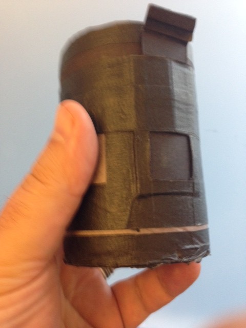
- Camera From the Front…
-
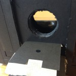
- The stop is just taped in place. The meniscus is concave forward, about one inch back.
-
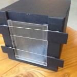
- We used a piece of plexiglass with one surface frosted as a ground class. Held in place with rubber bands, it can be removed and replaced with the film holder.
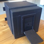
It’s a pair of boxes about 7″ across which telescope together. To create a bit of a light trap, there is both an inner and an outer box in the back, and the section which holds the lens slips in between those two, and also provides a rough focussing mechanism. The lens is a meniscus with about 150mm focal length, and about 50mm in diameter. It’s not an achromat, just a simple lens, configured as a Wollaston landscape lens. 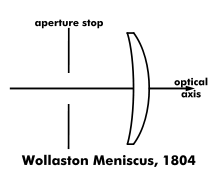 I constructed a small box to hold it about 1 inch behind the front of the camera, and then punched a 1/4″ hole in some black paper to serve as a stop. Instead of a true shutter, I decided to just make a little trap door. For our first tests, we were going to image directly onto photographic paper, which had an ASA rating of around 3 or 4. With the 1/4″ stop in place, my camera operates at around f/24. To make my first “selfie” in room light, I guestimated an exposure time of 30 seconds. The first exposure was far too light. I then caved and used a smartphone app to give a better estimate, and it suggested a three minute exposure time. I shot this on ASA 3 positive paper. I triggered the shutter myself, then sat down and tried to be as still as possible. When the time was up I got back up and closed the shutter. Into the darkroom… and bathing in the rinse!
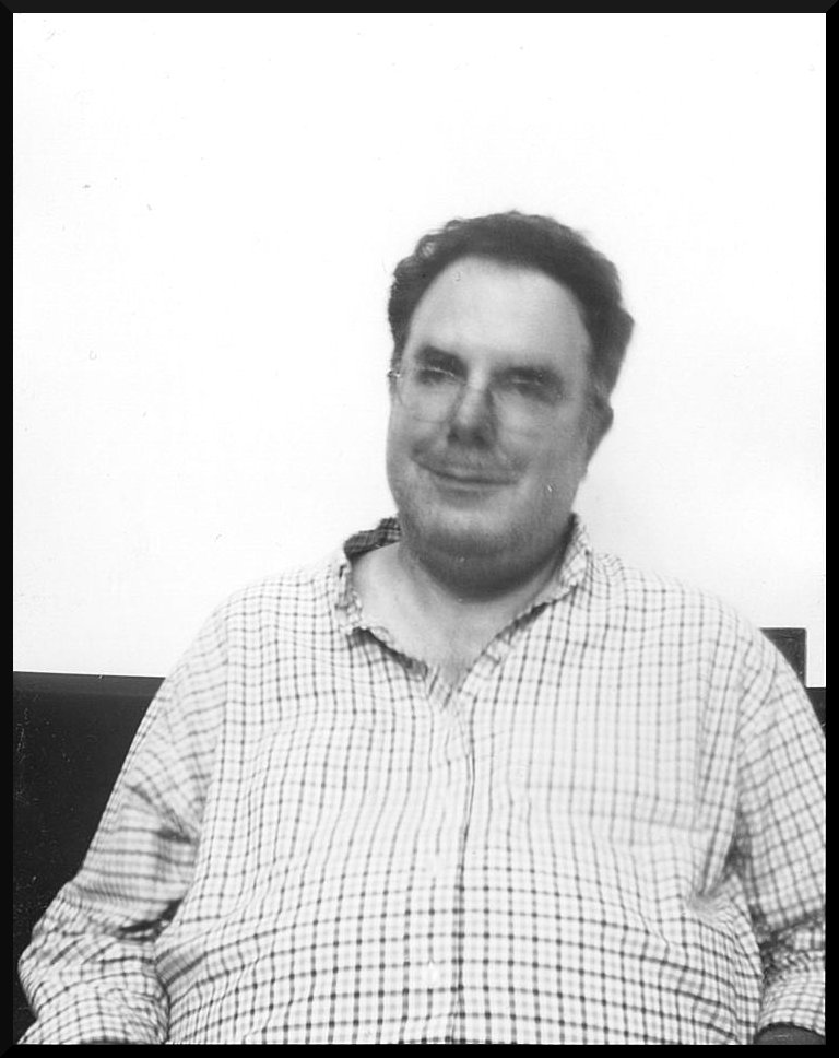
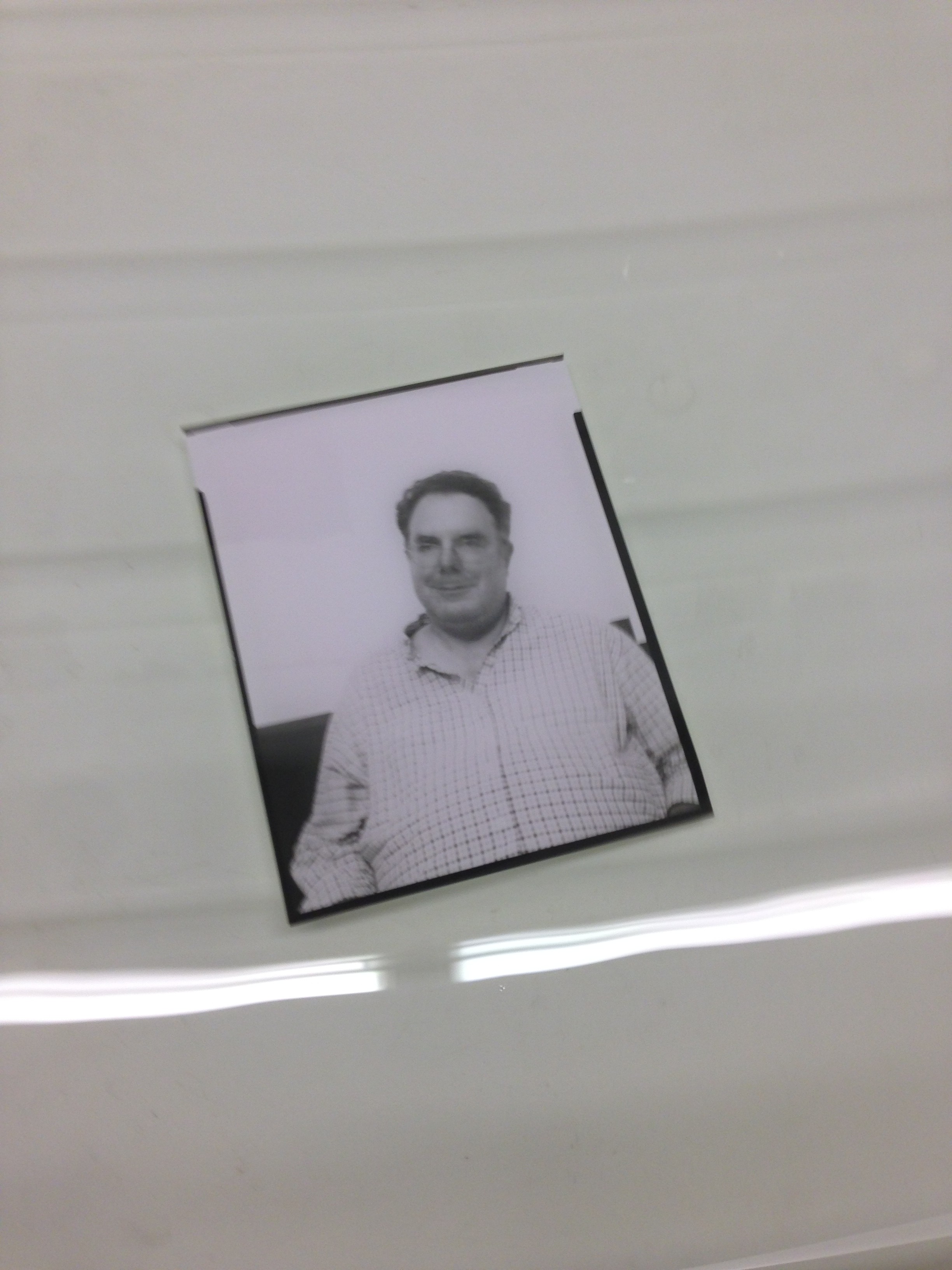
I cropped the picture and scanned it, cropped it, did a very tiny exposure tweak to darken it a bit (probably should have left it in the developer a touch longer), and here’s my selfie:
I’ll try to get some new shots next week. But it’s a fun project, I urge anyone to give it a try. These simple lenses are more effective than you would think.
I recall burning three or four weeks of a sabbatical getting Saccade.com on the air with Wordpress. So much tweaking…