April 13, 2019 | My Projects | By: Mark VandeWettering
I’ve slowly been trying to do some woodworking projects. I have very little skill and experience. In the past, I had (barely) enough skill to put together some simple Dobsonian telescopes out of plywood, using mostly a handheld router and a jigsaw, but they weren’t actually very accurately made (especially compared to the tolerances the optics were made, which measured in millionths of an inch).
While I had a hand held router (a big, rather heavy one) I didn’t have it set up for use as a router table. A few weeks ago, I took a 20% off coupon and bought a new little 1 3/4 HP router with a “table” for around $80. It is frankly not that great: a little hard to adjust the bit height, but I’ve only done a few test cuts with it. I thought that I’d like to have a stand to put it on so it would be at a convenient height. On top of my bench, it would be too high, and on the floor, well, let’s just say as I’m getting older getting up and down off the floor in my garage isn’t the most fun in the universe.
So, I thought I’d build a stand for it so that the top of the bench would match the 36″ height of my (very successful) rolling bench that I built a couple of months ago. I didn’t bother drawing any complicated plans at first. My idea was to basically cut 8 pieces of 2x4s to a 20″ length, and then rip cut the curved edges off each leg so they would be 1 1/2″ x 3″. I’d then join two of them into an L shaped bracket in each corner with glue and screws, cut rails to stretch between them and then fasten them together using a pair of Kreg pocket screws at each end.
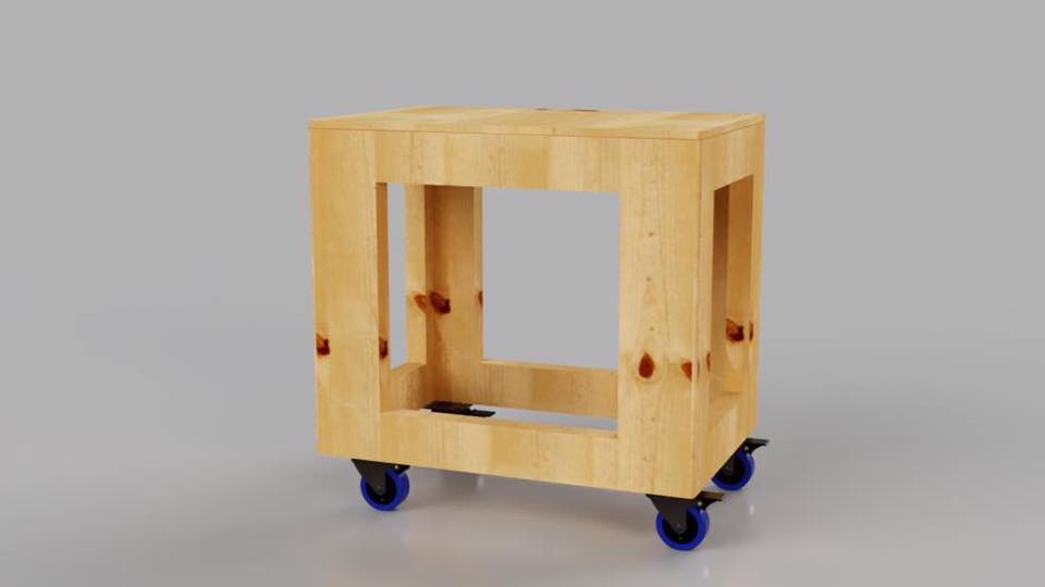
This is a little bit of a skill building exercise, since I have relatively little experience with my new little DeWalt table saw. The ripped 2x4s weren’t as flat as they would have been if I had a proper jointer and thickness planer, but they did come out more square than they would have otherwise. About halfway through the build, I had a problem I couldn’t visualize, so I ended up making a model of the bench in Fusion 360. I didn’t do the complete model (it lacks the bottom shelf and a couple of braces) but it did show the overall dimensions and helped me clarify some of my thinking.
The basics of the rolling table as modeled and rendered in Fusion 360.
I knew I wanted to have some rollers on the bottom (optimizing my space around moving stuff seems like a good strategy) and I was going to use up some 1/2″ plywood for the top. I also wanted to cut a shelf to go in the inside. On my rolling table, I made part of the lip just the 3/4″ edge so I could clamp things to the edge of the bench, but since this will basically be a dedicated stand for the router, I just decided to leave the 3″ thick top frame around all edges. Originally, my plan was to cut the top oversize and trim it to exact dimensions with a flush trim bit, but in the end I decided to just leave the 3/8″ overhang around all four sides because it seems nice, and doesn’t harm anything.
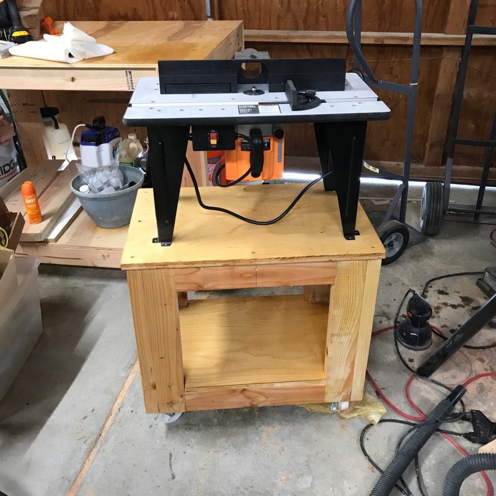
Anyway, this morning I finished the construction. I still need to get the hardware to bolt the table down to the top, but here’s what it looks like:
A few finishing touches (or is it touches of finish?) needed, but it’s good to go as soon as I bolt down the router table.
Here are some general thoughts from the build…
It’s pretty square, but not absolutely right. I tried to use my small machinist square and my large carpenter’s square on every joint, and it’s close. Much closer than probably any carpentry I’ve ever done, and given that I’m using construction grade lumber, perhaps that is as good as I could hope for.
The dimensions were a bit hard to wrap my head around. I ended up using 3/4″ plywood for the top, so it’s was going to be 1/4″ taller than my other bench, but in the end it turned out more like 1/2″. Similarly, when notching the shelf out for the bottom, it turned out to be slightly off in a couple of areas, making for a loose joint on one side and a tighter joint on the other. Frown. Oh well. In the end, it was tight enough that I didn’t even bother screwing it in place.
I broke a bit off while drilling a countersink hole. The tool steel crappy countersink/drill combos I bought at Harbor Freight are single fluted and made from tool steel, and generate a lot of heat while drilling. I wasn’t paying attention, and snapped one.
I wasn’t paying attention with two Kreg Screws and over tightened them, which drove them out the back. I need a lighter touch on the impact driver.
Don’t balance your can of boiled linseed oil on top of what you are working on. I dumped a bunch of it on myself when I knocked it over, and that’s why the front in the picture looks unfinished: I had to clean up a mess and tossed my sweatshirt into the wash with a lot of soap.
The only joint I did which wasn’t close to flat was one of the bottom ones underneath a caster. A few seconds with the belt sander flattened it.
I think design wise if i did it again, I’d raise the bottom rails up about 3″. This makes the shelf higher, and easier to get to, and the extra space makes it easier to roll over stuff on the floor. It would also avoid an odd routing problem with the Kreg screws intersecting the area where I’d bolt the casters in place.
Having my assembly table was a god send. It made so much of the work more accurate and more relaxing.
I need at least 2 more 36″ bar clamps.
Still, I had a lot of fun, and it looks great. The frame is way over engineered. The rollers are only rated for 110lbs each, but I’d trust the frame to hold well over 600 lbs or more. I only bought 2 2x4s to add to 2 more that I had, and used scrap plywood that has been in my garage for over a decade, so the total cost in materials was under $20, most of which were the casters.
Carmen wants me to design and build a potting table for our back patio, which will probably be our next project. Stay tuned for more woodworking.
April 3, 2019 | My Projects | By: Mark VandeWettering
So, my idea is to use a cheap but reasonably accurate RTC chip module based upon the DS3231 chip to periodically wake a sleeping Arduino. I tried getting it working yesterday, but had little luck. I don’t know whether it was Bailey’s insistence on being petted or simple sleep deprivation, but it eluded me yesterday. Today, I decided to go about it more methodically, and with the help of my trust Rigol DS1102E oscilloscope, I made sure that the module was generating a proper pulse stream, and eventually stumbled on the right order of operations to get this working.
For the purposes of this demonstration, I’ve programmed ALARM_2 to trigger every minute (it fires when the seconds are 00) and then programmed ALARM_1 when the trigger matches 30. This means that the interrupt fires to wake up the Arduino every 30 seconds. When it wakes at the moment, it doesn’t do anything particularly interesting: it just prints the time and temperature (which doesn’t seem right, so I’ll have to dig into why).
Anyway, the code isn’t particularly complex, but there were a few details to work through, and it might be useful in the future. It will require a tiny bit of extra work to (say) trigger every 5 minutes. You basically will have to use the setAlarm function to set the alarm to go off at a particular point in the future, and when that alarm is triggered, then tell it to trigger again 5 minutes in the future. I don’t foresee any trouble.
Anyway, here is the code:
#include <LowPower.h>
#include <DS3232RTC.h>        // https://github.com/JChristensen/DS3232RTC
#include <Streaming.h>        // http://arduiniana.org/libraries/streaming/
#include <Wire.h>

/*  _   _
 * | |_(_)_ __  ___ _ _
 * |  _| | '  \/ -_) '_|
 *  \__|_|_|_|_\___|_|
 *
 * Some simple code to test the idea of using a DS3231 module's "alarm"
 * functions to periodically wake up an Arduino which is in POWER_DOWN
 * mode so that it will do something interesting.   This is really just
 * a skeleton now, but will serve as an outline for a more advanced sensor
 * sketch.
 *
 * Written by mvandewettering@gmail.com
 */

const int wakeupPin = 2 ;

volatile int woken = 0 ;

void
wakeUp()
{
    woken = 1 ;
}

void
setup()
{
    pinMode(wakeupPin, INPUT_PULLUP) ;
    pinMode(LED_BUILTIN, OUTPUT) ;

    Serial.begin(115200) ;
    delay(50) ;
    Serial.println(F("WAKING UP...")) ;

    Serial.println(F("I2C set to 400K")) ;
    Wire.setClock(400000) ;

    setSyncProvider(RTC.get);   // the function to get the time from the RTC
    if(timeStatus() != timeSet)
        Serial.println("Unable to sync with the RTC");
    else
        Serial.println("RTC has set the system time");

    Serial.print("::: INITIAL TIME ") ;
    printDateTime(RTC.get()+7UL*3600UL) ;
    Serial.println() ;
    delay(50) ;

    // initialize the alarms to known values,
    // clear the alarm flags, clear the alarm interrupt flags
    // ALARM_1 will trigger at 30 seconds into each minute
    // ALARM_2 will trigger every minute, at 0 seconds.
    RTC.setAlarm(ALM1_MATCH_SECONDS, 30, 0, 0, 0);
    RTC.setAlarm(ALM2_EVERY_MINUTE, 0, 0, 0, 0);


    // clear both alarm flags
    RTC.alarm(ALARM_1); RTC.alarm(ALARM_2);

    // We are going to output the alarm by going low onto the
    // SQW output, which should be wired to wakeupPin
    RTC.squareWave(SQWAVE_NONE);

    // Both alarms should generate an interrupt
    RTC.alarmInterrupt(ALARM_1, true);
    RTC.alarmInterrupt(ALARM_2, true);
}

void
loop()
{
    // The INT/SQW pin from the DS3231 is wired to the wakeup pin, and
    // will go low when the alarm is triggered.  We are going to trigger
    // on the falling edge of that pulse.
    attachInterrupt(digitalPinToInterrupt(wakeupPin), wakeUp, FALLING) ;

    // Go into powerdown mode, waiting to be woken up by INT pin...
    LowPower.powerDown(SLEEP_FOREVER, ADC_OFF, BOD_OFF) ;

    // For now, let's just ignore transitions on this pin...
    detachInterrupt(digitalPinToInterrupt(wakeupPin)) ;

    // We have to clear the alarm condition to make the pin go back to
    // the high state.   I'm clearing both of them, because we are
    // triggering every 30 seconds (in this example)
    RTC.alarm(ALARM_1) ; RTC.alarm(ALARM_2) ;

    // Now, we can do whatever we want to do.  For now, we just get
    // the current time and the temperature (which doesn't appear to
    // work, and will be what I'm investigating next)

    printDateTime(RTC.get()+7UL*3600UL) ;
    Serial.print(" ") ;
    Serial.println(RTC.temperature()) ;
    delay(50) ; // allow serial to drain, otherwise we'll go to sleep
		// before the buffer empties.

}

void
printDateTime(time_t t)
{
    Serial << ((day(t)<10) ? "0" : "") << _DEC(day(t)) << ' ';
    Serial << monthShortStr(month(t)) << ' ' << _DEC(year(t)) << ' ';
    Serial << ((hour(t)<10) ? "0" : "") << _DEC(hour(t)) << ':';
    Serial << ((minute(t)<10) ? "0" : "") << _DEC(minute(t)) << ':';
    Serial << ((second(t)<10) ? "0" : "") << _DEC(second(t));
}
If it turns into something more interesting, you all will be the first to know.
April 3, 2019 | My Projects | By: Mark VandeWettering
Last night, I did a small amount of work on two projects.
I applied some Wood Bondo to a couple of bad defects in my garden bench project. I hadn’t used it in a while, and forgot what a pleasure it was. Sanding should be finished up shortly and I’ll definitely have it painted and finished this weekend.
The other thing I worked on was trying to prototype the main control loop of my IoT sensor project. Since I got the basic radio hookup done last night, I thought I would work on a slightly different issue.
My recent musing have been concentrating around reducing the power consumption of these boards. The way that is normally achieved is by putting the processor to sleep, effectively telling it to halt the main processor for a predefined amount of time. Then, either in response to a timer event or an external interrupt, the processor can wake up, read all its sensors, and log it to a local SD card or transmit the measurement wirelessly before going back to sleep.
Some microcontrollers have elaborate timing modules that can run while the main processor, but that is not the case for the Arduino. It just has a single “watchdog” timer that can serve to wake the processor back up, and it is relatively inflexible: it can only be set for a small set of intervals, the maximum length of which is eight seconds. It’s also not particularly accurate, since it is clocked by an RC based internal oscillator that operates at 128Khz. You definitely can try track time this way, but it seems a bit complicated and a little messy
As it happens, I have a fair number of DS3231 clock modules lying around. The specifications have an accuracy of ±2ppm from 0°C to +40°C , which translates to an accuracy of about one minute per year. I could live with that.
The DS3231 also includes an alarm module. This enables you to program two alarm registers with times that will trigger the alarm when matched. There are two registers (ALARM_1 and ALARM_2) and you can query whether either has been triggered, or you can configure the the chip to toggle the SQW output pin low when the alarm goes off. I found this primer to be pretty helpful. What was not helpful was that my cat Bailey kept on jumping into my lap while I was trying to concentrate, so while I managed to get the basic “polling” based code to work, I couldn’t quite wrap my head around getting the sleep mode and interrupt stuff to work. I think that tonight I’ll pull out my oscilloscope to ensure that the proper signals are being generated by the board, and then at least narrow my confusion to where I can hopefully eliminate it.
In the mean time, I’ve been spending some of my spare time reading all the tons of useful information on The Cave Pearl Project website, including this awesome collection showing how build their Pro Mini Data Logger. The accompanying video play list shows lots of tiny bits of cleverness in how they prep the various boards and attach them together in a clever way to build a nifty little datalogger for less than $10 in parts. Well worth your time to watch.
April 2, 2019 | My Projects | By: Mark VandeWettering
I must admit to a certain amount of jealousy about people who demonstrate an ability to start and finish large projects. Granted: I have a full time job and that job is not tinkering with my little home projects. But when I see someone construct a complex prototype of electronics, a large piece of woodworking, or simply the ability to regularly author content on Youtube or their blog, I feel like a bit of a slacker.
It’s not that I don’t actually get things done. I do. I just always feel like my progress proceeds at a slower pace than I would like, or even seems reasonable.
So… in my head I have a nebulous goal to create a new little project to explore building some prototype IoT modules that have the following characteristics:
Cheap. It’s not hard to build capable modules without any regard to budget. I would like the price of each module to be around $5.
Re-usable. Much like Cook’s “Standard Nano”, I want to be able to have a basic core around which I could create a variety of sensors.
Low power. I want the the modules to be able to be powered by batteries, and they should for a time measured in months. Making a unit which is solar powered is possible, but probably interacts with the “cheap” requirement, and there may be situations where solar power is inconvenient.
Wireless. The Cave Pearl Project has many sensors which record data to an SD card, but I’d like to have it sending live data back to a server where I can interact with the nodes in real (or at least near real) time.
I’m not the first person to think of this kind of thing, and the path seems pretty obvious from a hardware perspective.
Arduino Pro Mini 3.3V 8Mhz costs about $2.45, and can easily be adapted to lower power consumption by disconnecting the power LED and (perhaps) doing the same for the power regulator.
Sensors. Some are likely to be free, or every nearly so. You can do temperature lookups with cheap components or even none at all. Sensors that detect light, voltage, current, or things like reed switches are often very inexpensive.
Batteries.
Containers. (I like to use small lunch style boxes from Dollar Tree).
I think that we’ll be a bit above $5, but certainly less than $10 per unit.
So, I thought I’d do a proof of concept. Using the Arduino Pro Mini for the final sensors makes sense, but it’s easier to prototype with breadboards and a couple of spare Unos that I have lying around. I dusted them off.
You have to be a bit careful using the NRF24L01+ boards with 5V. While the inputs are 5V tolerant, you have to be sure to just pass 3.3V to the module. Every reference I found on this module makes sure to mention this. And this is where I got into trouble.
You see, I had some cute little adapter boards lying around to make it easier to hook these up to 5V Arduinos. They bust all the pins out into a straightforward layout that is more clearly labelled, and include the decoupling capacitors that make the modules run more stably. I had them on hand, so I thought I’d give them a whirl.
So, I hooked them up, loaded up the the “scanner” example sketches that came with the RF24 library I chose, and…
It printed out data, but it was essentially all zeros.
Double checked the wiring. Triple checked. Still nothing.
Came back the next day. Was it a bad module? Swapped it out. Still the same. Swapped out the Arduino. Nope, still the same.
Damnit, what was it? Should I get out the scope? Was I an idiot who just didn’t wire things properly? Was the library just crap? I mean, it didn’t appear to actually try to ensure that the SPI bus was communicating properly. You can just disconnect power to it (or not power up the module at all) and it would all be the same…
I had something in the neighborhood of three or four hours into it. I was thinking about the plan for the next day’s testing as I prepared for bed. I was just lying down and pulling in the covers, and it hit me… I stood up, walked downstairs, made a small change, and fired up the module and it worked perfectly.
The problem was stupid. You see, I was using the adapter boards. They have a 3.3V regulator on board. Of course, you need a bit of headroom above 3.3V to have it generate that voltage. After all the dire warnings from my reading about being careful to hook up the modules to 3.3V, I had passed 3.3V into the VCC pin on that module. That feeds into the regulator, but without sufficient headroom to hold 3.3V to power the module.
I moved the VCC of the adapter module to 5V, and it fired right up.
Dumb dumb dumb dumb dumb. And hours wasted.
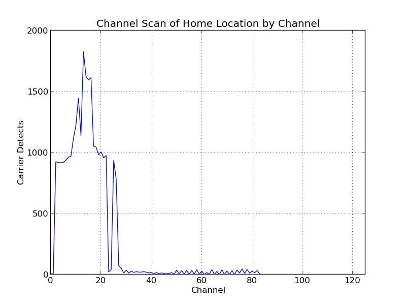
Anyway, I got it working, and then did a scan for a half hour or so to figure out what channels are likely to be free for use. It was pretty apparent that most of the 2.4Ghz activity in my house is concentrated down at the bottom edge of the band even scanning by eye, but I summed up all the carrier detects that it logged during that time, and with a little Python/matplotlib magic:
Any channel up above 85 or so should be smooth sailing.
Oh well, that took me longer than I would like, but I have it working. Next step will be to get one of these NRF24L01+ modules working on a Raspberry Pi. My idea is that all sensors should send information to the Pi, and the Pi will inject it as messages to my MQTT broker for further processing. Then, I can process events with Node Red.
Stay tuned, and hope that I’m not so dumb at every step of the way.
March 24, 2019 | My Projects | By: Mark VandeWettering
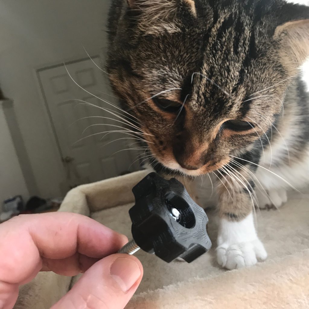
So, I’m trying to get a little more adept at wood working, and one of the things that I’m doing as a “skills building” exercise is to design and fabricate some new jigs and accessories for my table and miter saw. One of the things that I thought would be cool would be to design and 3D print some plastic knobs that I could use.
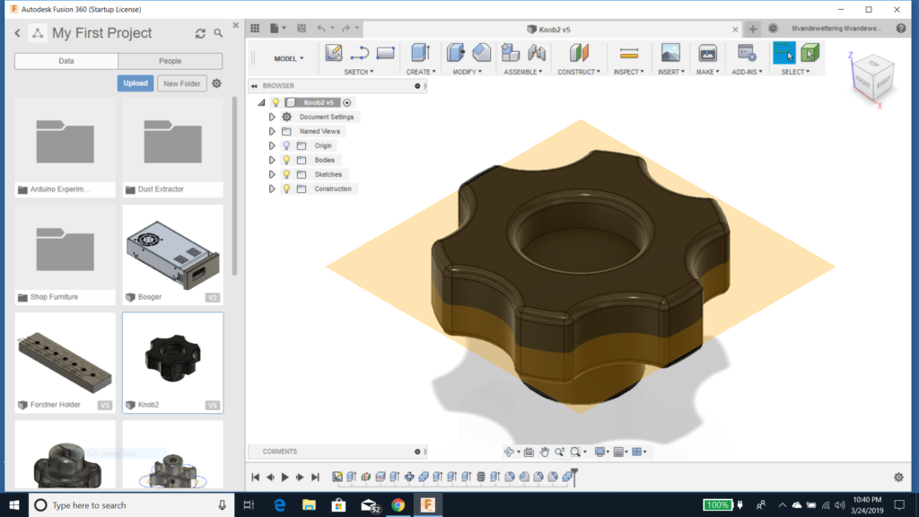
I had some idea as to what the kind of knob I wanted to make would look like, and from time to time I’ve been trying to gain some experience designing objects using Fusion 360. The basic ideas that I had was to make a knob a little under 2″ in diameter, with a sort of six lobed shape, an inch thick and threaded with a 1/4×20 thread.
So here’s what I came up with…
I am still pretty new to Fusion 360, but I was able to model it in an hour or so after a couple of false starts. And I printed one, which I then threaded onto a 1/4×20 bolt that I had lying on my workbench.
Bailey was impressed.
A couple of issues made it less than 100% successful.
First of all, the threads are quite tight. I could not screw the bolt into the knob by hand, I needed to use a screw driver. I thought I had a 1/4×20 tap lying around somewhere, but I haven’t been able to find it. I suspect that if I ran the tap through the threads, it would loosen it up significantly. Being tight can either be a flaw or feature. For a jig that you tighten by hand where the knob acts as a nut for a carriage bolt that you loosen and tighten often, you might want it to be a little bit looser. But if you use this to hold a machine bolt that you thread into a threaded insert, the tightness is probably a feature. I’ll have to print a few once I refine the model and do some testing in different modes.
The second is that I was trying to figure out a way to print an attractive knob without using supports. If I printed it with the small end against the bed (as conceived above) then the flange would need a support. I could slowly increase the size so that the overhang could be printed in one pass, but that seemed kind of odd.
The other way is to print it the other way around, with the big face against the bed. The problem here is that I wanted a recess to hide a washer and the head of a bolt if I decided to use the knob as a big thumbscrew. That recess would seem to require a support, but I thought it might be fun to try a technique I had seen before, which was to create a sacrificial “bridge” to hold the inner hole, which I could then remove with a quick bit of Xacto work.
So that’s what I did. I created a 0.25mm thick disk that covered the tapped hole. Since I was printing with a 0.2mm layer height, that layer should just be a single layer thick.
It worked! Well, not perfectly. I haven’t got the best settings for bridging using PETG in my slicer, so that layer was a little droopy and didn’t stick together very well. I’m thinking that I should increase speed and fan while bridging, and I might get a better result.
I could have just cut this stuff off with an Xacto, but I decided to just hit it with a 1/4″ drill in my drill press. This was actually a bit of a mistake because I didn’t hold the knob in a vice. Once the bit hit the plastic, it dug in quickly and tore it out of my hand. I probably should have used a small conical countersink instead.
I was also thinking that if I wanted make a looser version of the knob, one simple way might be to scale just the X and Y in the slicer by a small amount, say 3% or so. I’ll try that when I get an hour or so to try, and that probably won’t happen until I experiment to get better bridging settings.
I noticed a couple of other tiny issues with the model which I will probably refine. Perhaps another round tonight, but I have other projects to work on, so it might not happen until later in the week.
If you are exceptionally bold you can try downloading the STL file and printing one of your own. Drop me a comment if you like it.
March 20, 2019 | My Projects | By: Mark VandeWettering
Last night, the weather was pretty rainy. I woke up a couple of times during the night (once, when my little cat friend Bailey decided to check my breathing and started head butting me around 4 AM) and heard a lot of rain falling on the roof. When I woke up, it was fairly wet outside. I made myself a cup of tea and settled into check messages and email…
And the power went out.
Sigh. I could have used my phone and the cell service, but instead, I just spent a few minutes thinking.
Like about my battery backed up temperature/pressure sensor I had running in the garage, which is battery backed up. And since it sends its data to the MQTT server at io.adafruit.com, it should wo…
Oh, except of course my network is down.
It got me thinking that perhaps logging data to a local SD card isn’t actually the worst idea. Maybe once a day or so, it could wake up and send all the backlogged data to the server, but continue to log data locally.
And while I could use a microcontroller like the ESP8266, those things take a lot of current. Maybe it was time to look into something else that could be efficiently powered down and then only power up the remote peripherals (like a radio) when needed. And instead of using any kind of fancy charging circuit, maybe I could make something that is just powered from either Alkaline batteries with a run time of maybe a year.
As it happens, last night I found a couple of Arduino Minis and a USB/serial connector, so it seemed to me that using one of those would be pretty reasonable. But I was pondering a couple of issues: just what is the standby current of an Arduino Mini when in deep sleep mode? How much current does the ubiquitous power LED consume?
The breakdown seems to be that if I use a 3.3V 8Mhz Arduino Mini which is unmodified, I could expect about a 4.74mA current running flat out, and about 0.9mA while sleeping. Most of the sleep current is actually the Power LED, which draws about 0.84mA. It isn’t had to get rid of that (just cut a trace and/or destroy the LED with some snips) and then you are down to just 0.054mA during sleep. Very nice.
You can further reduce the sleep current by getting rid of the voltage regular, which may or may not be feasible depending on the use case. I was curious about what voltage I could use as input if I got rid of the regulator, and it appears that the ATmega328P is good from about 2.7V to 5.5V, which is a very broad range. You can simply feed that into the VCC. Sleep current is down to around 4.5?A in power down mode. Really, really good.
But it might be worthwhile use a better regulator. The Microchip MCP1700 has a quiescent current down in the 1.6uA range, which might be worth looking into. There is a lot of information about the efficiency of these regulators on the page linked above. I’ll have to look into it some more.
I should note that some of my thinking about this today was probably nudged by the following video @JeremySCook
I thought there were a couple of cute ideas in here. He used the Arduino Nano instead of the Micro but the form factors are pretty similar. I liked his way of soldering down DIP switches to provide some inputs, and using some shrink wrap to make a nice tight little package. He also pointed out these cute little battery holders with built in power switches that I hadn’t seen before. But I was a bit concerned about the use of the Nano. The USB interface chip draws about 15mA, and the Nano is nominally a 5V chip, so I thought that supplying just 6v to such a system would result in very short life, as the CR2032 batteries are pretty low capacity already, and 6v is not really enough headroom above what the voltage regular needs to provide 6v. Still, definitely some good ideas.
March 20, 2019 | My Projects | By: Mark VandeWettering
I’ve been slowly working toward getting a reasonably equipped garage for woodworking, and have been watching a metric ton of Youtube content made by woodworkers. Today, I ran across this nice list of things that you can 3D print to help out with various tasks, the most immediately useful being some knobs I can print for 1/4×20″ bolts. Shared with all of you, and archived for myself.
March 15, 2019 | My Projects | By: Mark VandeWettering
My experimenting with plane sharpening has (like so many other things) caused me to research stuff on the Internet. I’ve been working on grinding the back on my older plane using sandpaper cemented down to a flat piece of glass. It’s still not quite there after about a solid 30 minutes of work, and it’s pretty clear to me that the grit is breaking down and not cutting as fast as when it was new. So, toward that end I started to consider the possibility of investing in some sort of grinding stone. But, I don’t know anything about them, so I started reading. That’s when I ran across this page, with tons of information and designs for jigs that can be used to help make sharpening quick and repeatable. I haven’t absorbed it (or even read it all), but I’m stashing this link for future reading.
March 13, 2019 | My Projects | By: Mark VandeWettering
So, last night about 9:30PM I decided to spend a little time in my garage workshop. I cleared some items off the top of my rolling workbench and decided to do a short bit of work on two projects.
A couple of days ago I had started making a cross cut sled for my tablesaw. I had cut and glued two oak runners to a piece of 3/4″ ply. Today I trimmed the extra bits off from the board, and smoothed the ends with a bit of work using my belt sander. I took some extra time to rub some paste wax into the bottom, and now it slides easily in the miter slots. I didn’t feel like doing anything more on it, because I want to spend some time to double check my table saw blade for square before making any additional cuts. I have some 3/4″ ply cut to serve as the end fences already, but will need to chop it to length and glue up a double thickness to serve as the rear fence too. Perhaps I’ll get to that this weekend.
But, I didn’t feel like stopping, so I decided to try my hand at sharpening.
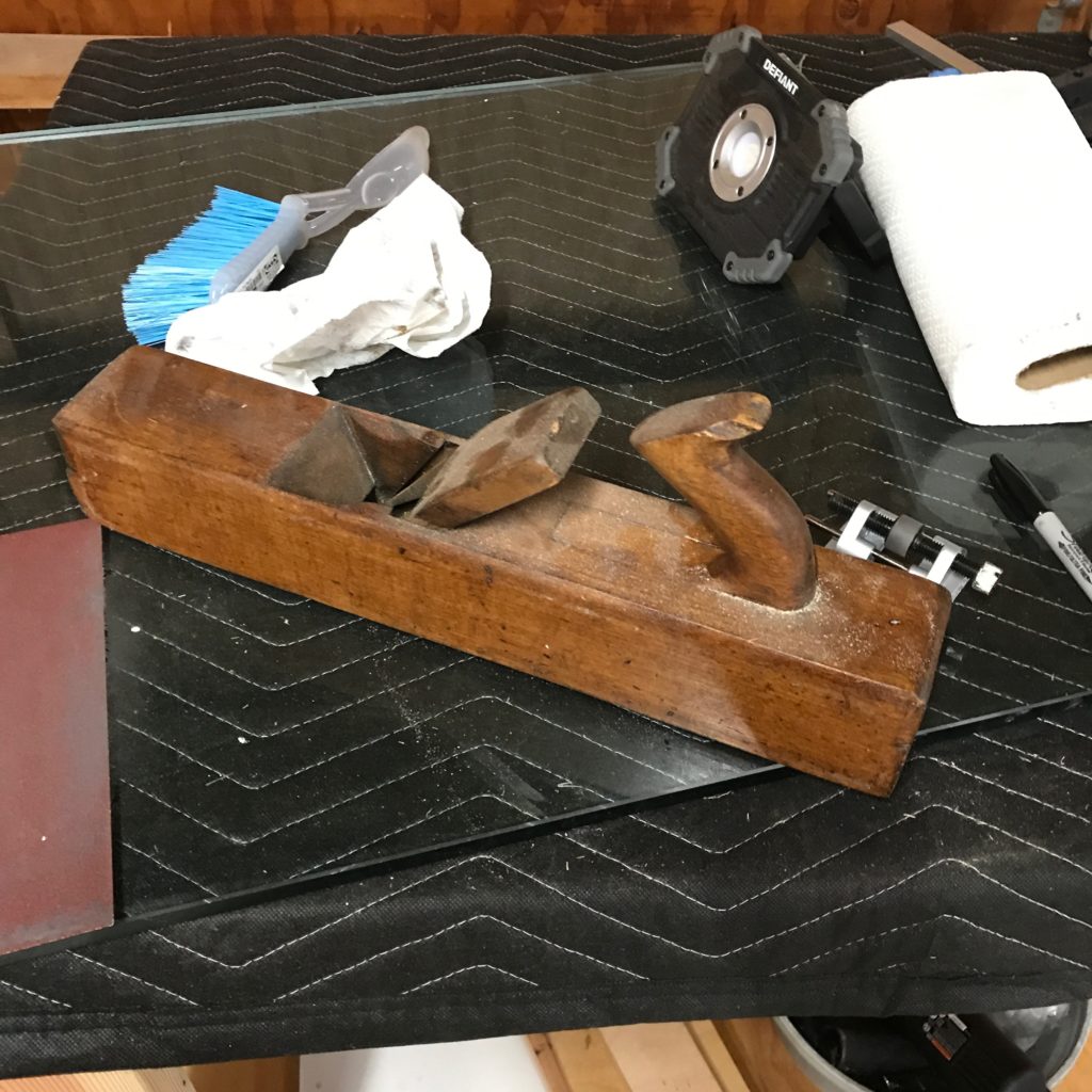
Old (and dusty) wooden fore plane. Bed length is about 16.5″…
Years ago, my wife got me a couple of planes as a gift. She had found these in some antique store and I had mentioned to her that I liked old tools, so she bought them for me (she assures me they were inexpensive). I always thought they were nice objects, but hadn’t either displayed them or converted them into working tools. One was a molding plane that I haven’t got any serious plans for, but the other is an old wooden fore plane, with a 2″ wide iron and about 16.5″ in length that appears to be in pretty good shape.
I thought I might actually try my hand at restoring it to working shape. And I figured the best way to start is to sharpen the tool iron. Inspired by Rex Krueger’s video:
I decided to give it whirl! I had a large 24″ square piece of flat tempered glass, and took a piece of 150 grit sand paper, prayed it with some 3M Super 77 spray adhesive, and glued it to one corner.
Examining the old iron, it looks to me like it hadn’t (perhaps ever) been properly sharpened (he say’s boldly, having literally no experience with it). The back looked like it had never been flattened, and the bevel was rounded and uneven.
A couple of weeks ago I ordered a honing guide from Amazon. The basic idea of this is to hold the iron at a particular angle that you can set by adjusting the amount of the iron that protrudes out the front, and the guide will hold the blade at the proper angle. For a 25 degree bevel, it required a 50mm (or 2″) protrusion. For fun, I decided to give it a try.
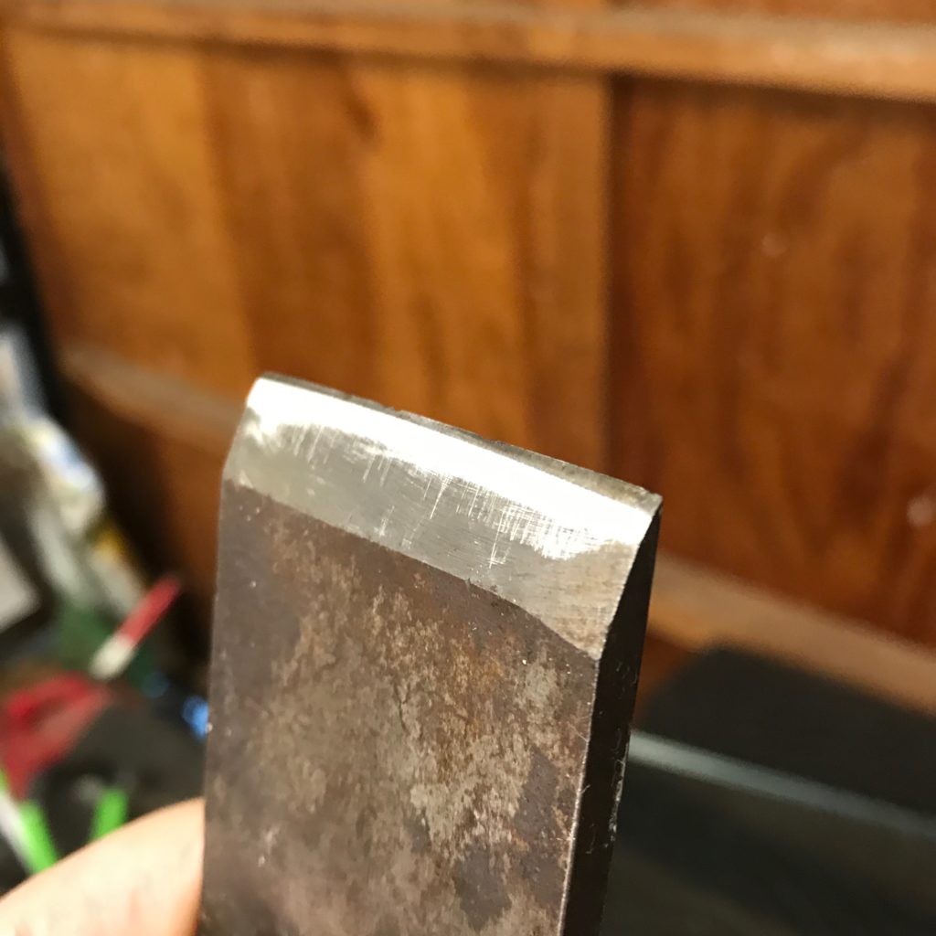
Hard to photograph, but the white area is the newly ground surface. As you can see the leading edge is blunter, and not even.
A few minutes of work revealed what I thought. The leading edge of the blade was actually much blunter than 25 degrees. It will probably take some work to get back to a single, consistent bevel.
My understanding is that many fore planes actually used a curved or cambered blade. This is because fore-planes were used to make fairly aggressive, overlapping cuts to roughly flatten stock. But there was a significant left to right change, so I thought it probably would be best to try for a simple, flat bevel, and worry about trying to adjust the camber at some later date.
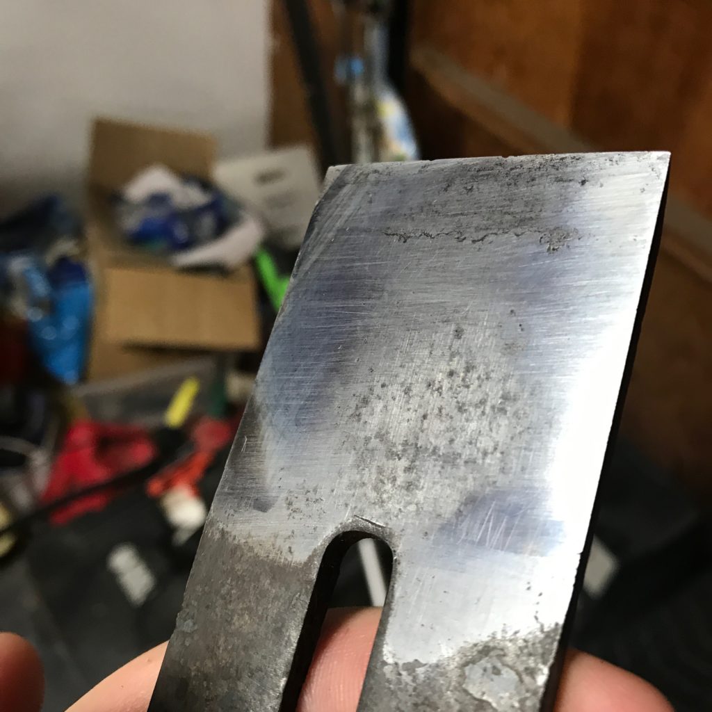
But first, I needed to flatten the back. I took the iron out of the honing guide and set to work. My goal was to get about 1.5″ of the back flat. A few minutes of work revealed that the center of the iron was obviously significantly concave, and pretty rough overall. There was also some general uneven-ness near the the leading edge, and one side looked like it was a a bit rounded relative to the rest of the surface.
After 15 minutes you can clearly see the concavity in the center, and the left side is a bit off as well.
I kept at it for about 15 minutes. It rather reminded me of my old days of working grinding telescope mirrors. Careful, even pressure, long strokes, examining your work at intervals.
It still needs a lot of work. While the portions to the left and right are now nice and bright and smooth, the leading edge is still a bit stained and uneven, and you can see a fair amount of concavity still remaining in the center, although it’s much better than when it began. It was getting late though, so this is where I halted for the night.
As I went off to sleep, I started to consider the meta question: how flat was flat enough? And why is having a flat back to the iron important anyway?
Ask questions, and the internet provides the answer. This article from Fine Woodworking provided me some light reading before sleep took me.
Anyway, the time in the garage was quite relaxing. I did decide that I needed to add another LED light strip toward the front side of the garage, because I was basically standing in my own light. Perhaps I’ll get to that this weekend.
Hopefully, my next update will be to let you all see how nice and flat this iron has become, and how I’ve ground a proper bevel. Stay tuned.
March 3, 2019 | My Projects | By: Mark VandeWettering
Okay, a few weeks ago I bought a little Dewalt DW745 table saw for use in my garage. I’ve never actually owned a table saw, but lately I’ve been wanting to do more construction, and I thought investing a fairly small amount of money in a table saw would be a good way to go.
And I’ve begun to do experiment with some cheap, simple projects to learn how to operate it and operate it safely.
The way I’ve decided to start is by trying to research and build some simple jigs to help me safely and accurately cut pieces of various types. One of the jigs which everyone recommends that you build is a cross cut sled.
I had some old 3/4″ plywood lying around my shop, left over from when I built my last telescope more than a decade ago. I decided to rip some pieces to form the bed and the two ends of the cross cut sled. It was good practice. All the pieces had nice clean edges, and sighting along them and checking them with a square shows the edges to be nice and straight.
The only part that I didn’t have was material to make the rails that will fit in the miter slots. While I have a fair amount of scrap plywood and softwood like Douglas Fir 2x4s lying around, I haven’t done any hardwood woodworking before, so I don’t have the usual oak or maple that most people use for it. I will probably go out and source some 1″ material I could trim down over the next few days, but while thinking about it, I ran across this nice video series of videos to help newbies like myself build their first cross cut sled.
They suggested that it actually is reasonable to cut runners out of plywood, at least if you use a good quality plywood like Baltic Birch. As it happens, I don’t have any of that either, but there is still a lot of good information here which I’m trying to absorb. If you are a beginning woodworker, you could probably learn some good stuff from this series too.
March 3, 2019 | My Projects | By: Mark VandeWettering
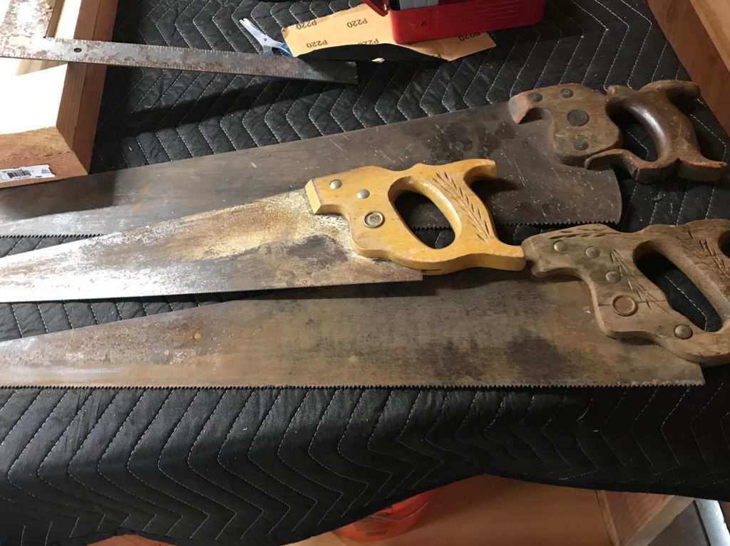
I heard some friends of mine that I haven’t seen in some time were having an estate sale, so I drove over to say hi and, well, to also see if they had anything interesting. Lately I’ve become interested in doing more work in my shop, and I’ve always had a bit of a fondness for old tools, even though I know almost nothing about them. I had a nice visit, and then dug around. In their old workshop, I found I found this trio of old saws, which they generously donated to me. They are a bit dirty and rusty, and I don’t know anything about old tools really, but I liked the shape of the handles and the wheat motif that was carved into the handles, and imagined that they were probably fairly old.
In fact, I think they are probably over a hundred years old. I took some photos, and will ponder what I’m going to do with them. At the very least they could stand a bit of rust removal and cleaning, and probably have some linseed oil rubbed into the handles.
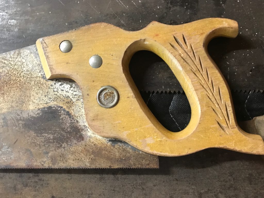
As you can see, these are a little rusty and dirty, but it’s mostly surface corrosion, and they are in pretty good condition. I doubt you would really call them sharp, but they are not missing any teeth, and they are straight and even. One has a fairly loose handle, and the one pictured on the bottom has a split in the handle. The handles are secured to the saws with screws which are (I believe) brass.
This one is probably in the roughest shape. As you can see, the wood is split right through the medallion in the center, and there is a fair amount of sticky, gloppy looking stuff stuck onto the handle, specially near the base of the wheat motif.
Here is a not very good picture of the medallion. It’s fairly corroded, but I haven’t tried to clean it yet. My guess is that it says “DISSTON”, but I’m not 100% sure. I looked at this quick identifying chart, and believe it to be a Disston D-23 or one of the related models. Neat!
The next saw:
has another dirty/gunky medallion.
It is pretty clearly another Disston saw, also tagged with USA. I think it might be a No. 76, but I’m not sure. If so, it’s a bit more rare than the first saw, and while the blade is in kind of gunky condition, the handle and hardware appear much better. Overall the feeling of the saw is more modern, but what do I know?
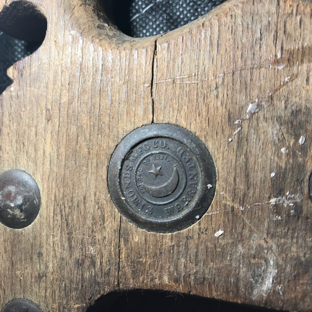
The last is a different manufacturer.
Rather odd construction to my eyes. The slotted/split construction is particularly odd, and the curves are more exaggerated. Looking at the medallion:
Reveals a kind of nice motif with a crescent moon and five pointed star, and “SIMONDS MFG CO. WARRANTED”. I wasn’t able to find too much more information about this in a casual Google, but it’s a cool medallion.
Anyway, I doubt I am going to be using them for much woodworking, but I thought they were cool objects. I’ll probably try to get them cleaned up at least, remove the rust and figure out some way to display them. If anyone has more knowledge/expertise about old handsaws you can email me or drop a comment. I’d love to know more.
March 3, 2019 | My Projects | By: Mark VandeWettering
A couple of days ago, I found out about thecavepearlproject.org through a link on hackaday, and an article which gave an interesting idea about how to do temperature sensing using an Arduino and no additional parts. I didn’t really recap the actual underlying technique. The idea was a fairly interesting one. The watch dog timer (WDT) in the ATmega328 (the chip of many Arduino variants) is normally used to help detect if your embedded application has crashed or hung. You configure the watchdog timer to trigger a routine (ISR, or Interrupt Service Routine) after a given interval, say one second. In your application’s main loop, every once in a while you “feed” the timer by calling the wdt_reset function. This resets the timer, and keeps the ISR from triggering. If your application goes into a loop or hangs, then the wdt_reset won’t get called, and when the timer expires, it triggers the routine (perhaps resetting system).
What does this have to do with temperature sensing? The WDT is driven by an oscillator inside the ATmega328, and which runs independently of the main (usually crystal) oscillator. And, as it happens, it is not engineered to be especially accurate or stable. It is not derived from the input crystal (crystal oscillators are normally pretty stable). In particular, it is not designed to be temperature stable. And it’s not. It’s that instability that makes using it for temperature sensing. You measure the time it takes to trigger the WDT, and then, with a little math (more below) you can figure out the temperature.
Anyway, that’s the theory. I wanted to give it a whirl. So, I tinkered together some code, using my favorite development environment platformio, and running on a Sparkfun RedBoard, with some other sensors that I had lying around: an Si7021 temperature humidity sensor and a DS3231 real time clock. Previous data logging experiments I had done mostly used to log data to the Internet (I mostly have been using ESP8266 boards like the WeMOS D1 Mini), but I was inspired by the work on The Cave Pearl Project website, so I decided to try to log the data to a MicroSD card instead. So, I tinkered this code together:
#include <SPI.h>
#include <Wire.h>
#include <SdFat.h>
#include <RTClib.h>

#include <avr/sleep.h>
#include <avr/wdt.h>

/*  _
 * | |__ _  _ _ _ _  _ __ _ _ _
 * | '_ \ || | ' \ || / _` | ' \
 * |_.__/\_,_|_||_\_, \__,_|_||_|
 *                |__/
 * an Arduino based data logger
 *
 */

#define BUNYAN_VERSION          "1.00"

////////////////////////////////////////////////////////////////////////
RTC_DS3231 rtc ;
////////////////////////////////////////////////////////////////////////

void
fault()
{
    Serial.println("::: SYSTEM FAULT RECORDED") ;
    delay(10) ;
    for (;;) ;
}

////////////////////////////////////////////////////////////////////////

////////////////////////////////////////////////////////////////////////
// microSD card adapter settings
////////////////////////////////////////////////////////////////////////

SdFat SD ;
SdFile f ;

void
motd()
{
    int ch ;

    if (! SD.exists("README.TXT")) {
        Serial.println("::: no motd") ;
        return ;
    }

    if (f.open("README.TXT", O_RDONLY)) {
        while ((ch=f.read()) > 0) {
            if (ch == '\n')
                Serial.write('\r') ;
            Serial.write(ch) ;
        }
        f.close() ;
    } else {
        Serial.println("motd: not found.") ;
        fault() ;
    }
}

////////////////////////////////////////////////////////////////////////
// It's useful to be able to detect all the devices on the I2C bus.
////////////////////////////////////////////////////////////////////////

int
i2cprobe(int addr)
{
    byte error ;
    Wire.beginTransmission(addr) ;
    error = Wire.endTransmission() ;
    return error == 0 ;
}

void
i2cdetect()
{
    char buf[12] ;

    Serial.println("    SCANNING ALL I2C ADDRESSES") ;
    Serial.println("    =======================") ;
    for (int i=0x08; i<0x78; i+=8) {
        Serial.print("    ") ;
        for (int j=0; j<8; j++) {
            if (i2cprobe(i+j))
                snprintf(buf, sizeof(buf), "%02X ", i+j) ;
            else
                snprintf(buf, sizeof(buf), "-- ") ;
            Serial.write(buf) ;
        }
        Serial.println() ;
    }
    Serial.println("    =======================") ;
}

////////////////////////////////////////////////////////////////////////

volatile boolean WDTalarm=false;

ISR(WDT_vect)
{
    wdt_disable() ;             // only fire once.
    WDTalarm=true ;
}

////////////////////////////////////////////////////////////////////////

#include "Adafruit_Si7021.h"
Adafruit_Si7021 sensor = Adafruit_Si7021();
////////////////////////////////////////////////////////////////////////

char msgbuf[40] ;

char fname[40] ;

void
setup()
{
    // Most of the time, we won't really have (or need) a serial
    // cable attached to the data logger, but during development it
    // is convenient, and I'm not really working at trying to eke out
    // every last bit of battery life, so we'll go ahead and turn it on
    // here.

    Serial.begin(115200) ;


    // wait for the serial port to be initialized
    while (!Serial) delay(10) ;

    Serial.println("BUNYAN Version " BUNYAN_VERSION) ;

    Wire.begin() ;
    i2cdetect() ;
    Serial.println() ;

#if 1
    Serial.println("::: testing WDT_count()") ;
    snprintf(msgbuf, sizeof(msgbuf), "::: CNT=%ld", WDT_count()) ;
    Serial.println(msgbuf) ;
#endif

    // I envision A0 to be connected to a simple resistor divider, so we
    // can keep track of the battery voltage.

    Serial.println("::: A0 set for analog input") ;
    pinMode(A0, INPUT) ;

    // Try to setup the SD card...
    snprintf(msgbuf, sizeof(msgbuf), "::: SPI MISO=%d MOSI=%d SCK=%d CS=%d",
        MISO, MOSI, SCK, SS) ;
    Serial.println(msgbuf) ;

    if (!SD.begin(SS, SD_SCK_MHZ(4))) {
        Serial.println("::: unable to initialize microSD card reader") ;
    }

    motd() ;

    if (i2cprobe(0x68)) {
        Serial.println("::: found DS3231 at I2C address 0x68");
        rtc.begin() ;
        if (rtc.lostPower()) {
            Serial.println("::: DS3231 lost power, resetting time.") ;
            rtc.adjust(DateTime(F(__DATE__), F(__TIME__)));
        }
        DateTime now = rtc.now() ;

        snprintf(msgbuf, sizeof(msgbuf),
                "::: %02d/%02d/%04d %02d:%02d:%02d [%ld]",
                now.month(), now.day(), now.year(),
                now.hour(), now.minute(), now.second(),
                now.unixtime());
        Serial.println(msgbuf) ;

    } else {
        Serial.println("::: could not find DS321 RTC module") ;
        fault() ;
    }

    if (sensor.begin()) {
        Serial.print(F("::: found "));

        switch(sensor.getModel()) {
        case SI_Engineering_Samples:
            Serial.print(F("SI engineering samples")); break;
        case SI_7013:
            Serial.print(F("Si7013")); break;
        case SI_7020:
            Serial.print(F("Si7020")); break;
        case SI_7021:
            Serial.print(F("Si7021")); break;
        case SI_UNKNOWN:
        default:
            Serial.print(F("Unknown"));
        }

        Serial.print(" Rev(");
        Serial.print(sensor.getRevision());
        Serial.print(")");

        Serial.print(" Serial #");
        Serial.print(sensor.sernum_a, HEX);
        Serial.println(sensor.sernum_b, HEX);

        float fT = sensor.readTemperature() ;
        float fH = sensor.readHumidity() ;

        int iT = (int) (100. * fT) ;
        int iH = (int) (100. * fH) ;

        snprintf(msgbuf, sizeof(msgbuf),
                "::: TEMP=%d.%02d RH=%d.%02d%%",
                iT / 100, iT % 100, iH / 100, iH % 100) ;

        Serial.println(msgbuf) ;
    } else {
        Serial.println("::: could not find temperature humidity sensor") ;
        fault() ;
    }

    int cnt = 0 ;

    do {
        snprintf(fname, sizeof(fname), "DATA%03d.CSV", cnt++) ;
    } while (SD.exists(fname)) ;

    Serial.print("::: Using ") ;
    Serial.print(fname) ;
    Serial.println(" for data.") ;

}

// https://thecavepearlproject.org/2019/02/25/no-parts-temperature-measurement-with-arduino-pro-mini-to-0-005c-or-better/

unsigned long
WDT_count()
{
    noInterrupts() ;
    MCUSR = 0 ;
    WDTCSR |= (1<<WDCE) | (1<<WDE) ;                    // prep for update
    WDTCSR = (1<<WDIE) | (1<<WDP2) | (1<<WDP1) ;        // and change it to 1s
    wdt_reset() ;
    WDTalarm = false ;
    interrupts() ;


    unsigned long st = micros() ;

    while (!WDTalarm) {
        set_sleep_mode(SLEEP_MODE_IDLE) ;
        noInterrupts() ;
        sleep_enable() ;
        interrupts() ;
        sleep_cpu() ;
        sleep_disable() ;
    }

    return micros() - st ;
}

void
loop()
{
    Serial.print("::: LOGGING TO ") ;
    Serial.println(fname) ;

    if (f.open(fname, O_CREAT | O_APPEND | O_WRONLY)) {
        Serial.print("::: ") ;
        Serial.print(fname) ;
        Serial.println(" open, logging data") ;

        // First, get the time
        DateTime now = rtc.now() ;
        snprintf(msgbuf, sizeof(msgbuf),
                "%ld,", now.unixtime()) ;
        f.print(msgbuf) ; Serial.print(msgbuf) ;

        // and the temperature and humidity
        float fT = sensor.readTemperature() ;
        float fH = sensor.readHumidity() ;
        int iT = (int) (100. * fT) ;
        int iH = (int) (100. * fH) ;
        snprintf(msgbuf, sizeof(msgbuf),
                "%d.%02d,%d.%02d,",
                iT / 100, iT % 100, iH / 100, iH % 100) ;
        f.print(msgbuf) ;
        Serial.print(msgbuf) ;


        unsigned long wd_cnt = WDT_count() ;
        snprintf(msgbuf, sizeof(msgbuf), "%ld,", wd_cnt) ;
        f.print(msgbuf) ;
        Serial.print(msgbuf) ;

        f.println() ;
        Serial.println() ;

        f.close() ;
    } else {
        Serial.println("::: Problem saving data.") ;
    }

    // Wait for a minute, then begin again...
    delay(5000) ;
}
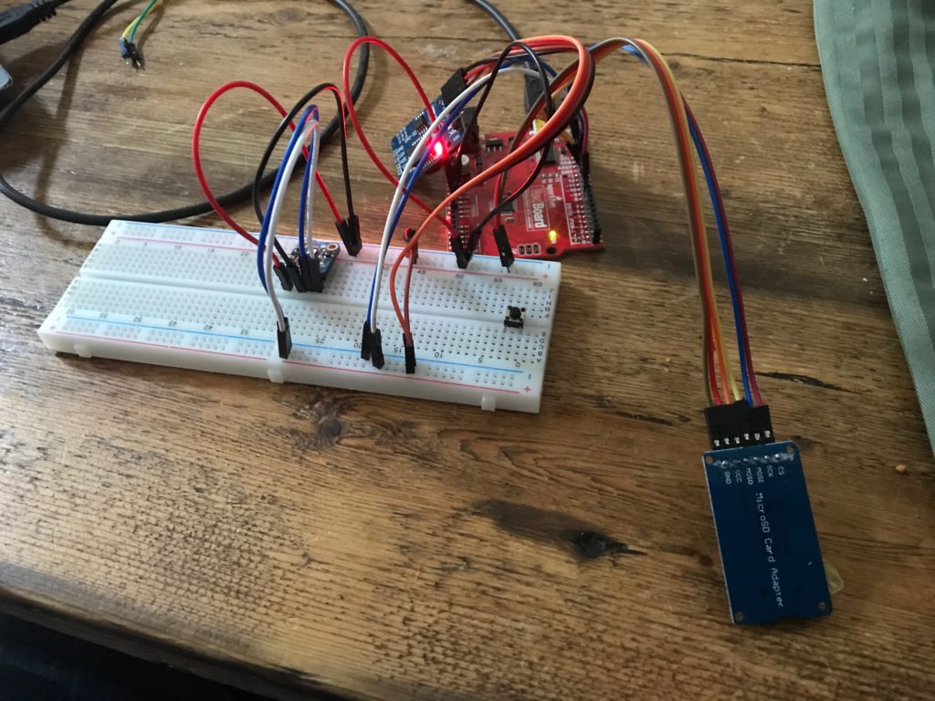
And I wired up the hardware on a breadboard.
Yes, it is just a mess, just like the code.
The data file looks like this. Each line consisted of a time stamp , the temperature and humidity reported by the Si7021, and then the time (in microseconds) that it took the watchdog timer to overflow.
I left this running on my dining room table overnight, recording the data every five seconds (overkill, but why not?) and in the morning I had a data file with about 7800 entries. So, the question was, what to do now? How could I figure out how to convert the raw counts into temperatures?
The answer is of course “math” and the tool I like to use when doing math with computers (particular when the math consists of lots of data) is the numpy library. It turned out that the numpy.polyfit function is just what we need. I wrote 17 lines of code (only two or three which are interesting) to compute an order 2 polynomial that will convert the counts into temperature. I also computed RMS error, and found that the RMS error for the fit curve was about .128 degrees. Not bad at all, and probably pretty comparable to the Si7021.
!/usr/bin/env python
 import numpy as np
 a = np.loadtxt("data008.dat")
 cnt = a[:,3] - 1e6
 temp = a[:,1]
 p = np.polyfit(cnt, temp, 2)
 ptemp = p[2] + cnt * (p[1] + cnt * p[0])
 e = ptemp-temp
 print "# rms error %.3f" % np.sqrt(np.sum(e * e) / len(e))
 for a, b in zip(ptemp, temp):
         print "%.2f" % a, b
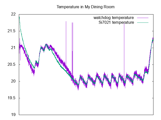
Here is a graph comparing the two (plotted with gnuplot):
As you can can see, there is a bit of deviation at the very beginning (perhaps caused because the board itself had not been powered before, and therefore may not be subject to self-heating), and there are a couple of glitches, but overall the predicted value is a bit noisier, but tracks the temperature from the “real” sensor pretty well.
What’s left is to try to calibrate the sensor over a much larger temperature range, and to potentially determine how to compensate changing battery voltage if I were to power it from an unregulated source. But it seems like a completely viable way to do temperature sensing, at least if you take the time to calibrate the temperature against a known source (the same coefficients will not carry over between individual boards).
Addendum: The code above was pretty simple, but I did encounter one issue. I had been slowly adding functionality to the sketch, when suddenly code that had worked before began acting erratically, resetting the board and generally causing chaos. I spent about 20 minutes scratching my head, then went away and came back to it later. I then realized that what probably was happening was that I was nearing (or exceeding) the amount of RAM memory for the sketch. I hadn’t been using the ATmega328 in a while, and had forgotten that it only has 2K, so that’s actually pretty easy to do. In addition, the SdFat library consumes a fair amount of RAM as well, so you have to be careful. I did a few things to trim back memory consumption, and should go back and make sure that all the constant strings that I use for information printout are wrapped in the F() macro to make sure that they are stored in flash. If you do not do that, then they get copied into RAM, which is no good at all for memory consumption, and almost certainly not needed.
February 26, 2019 | My Projects | By: Mark VandeWettering
Last night I began dusting off my solar project a bit. It still seems like we are at the bottom of the atmospheric river, so I don’t think it will be going outside any time in the near future, but I wanted to make some software changes.
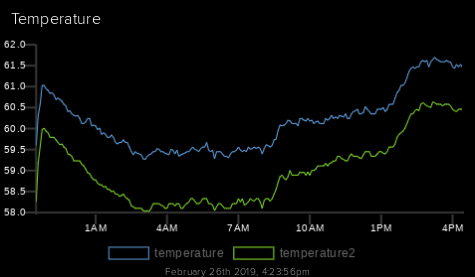
It uses a pair of temperature sensors and records it to an MQTT server. It revealed that my garage seldom gets below 55 degrees or so (not too surprising, since the weather here seldom gets that cold, but we did have a couple of snaps down around freezing). Over the last 24 hours it’s recorded the following:
From my garage…
This data comes from a Microchip MCP9808 board, and the temperature reported by an MPL3115A2 barometric pressure sensor. I haven’t bothered doing a calibration to see which one is more accurate, but you can see that they seem to report the same values up to an offset. Both are more accurate than I really need.
Several years ago I didn’t have such sensors in my junk box, and tried just measuring the forward voltage drop across a very cheap 1N4148 diode. That “worked” after a fashion. It wasn’t especially sensitive, since each bit of the value returned by analogRead() turned out to be about 2 degrees C. The post generated some comments however, and pointed out that I could use either the internal 1.1V reference or the actual internal temperature sensor to get more accurate values. It was fun, but soon after I got real temperature sensors which promised still better accuracy, and I didn’t revisit the issue.
But today I found an interesting and different approach on the Cave Perl Project Blog. The ATmega328p used on the Arduino uses an internal RC oscillator to run the watch dog timer. It runs at around 110Khz, but isn’t especially accurate. It is… you guessed it… highly temperature dependent. So, you can time the amount of time it takes the WDT to overflow, and with some math determine what the temperature might be. And it turns out that the results are likely sufficiently more accurate, perhaps down to around 0.1 degrees C, which is better than a lot of inexpensive sensors. There are some details which are interesting to read and think about, but I might have to try experimenting with this.
In any case, the website is actually pretty cool for other projects as well. It was founded to develop “a submersible data logger system for long term environmental monitoring projects” and has lots of other good data and ideas. I’ll probably be killing a few hours reading it tonight. I think you all could do worse than do the same. 🙂
February 23, 2019 | My Projects | By: Mark VandeWettering
I’m still heading toward changing my Creality CR-10 over to use a BLTouch bed leveling sensor, but I still need a few parts that I’m waiting on. I thought it might be a good time to try some prints with a filament that I never used before: namely a roll of Sainsmart TPU filament that I bought months ago but was too chicken to try.
TPU is a soft and stretchy filament which presents some challenges, especially for prints like the CR-10 which uses a Bowden extruder. The filament is pretty soft and compressible, which means that the extruder has to work very slowly to keep the pressure down sufficiently to keep it from bunching up and jamming in the printer. Most people also recommend modifications to the extruder to make sure that the filament enters the feed time immediately after exiting the feed gear. Otherwise a common failure mode is for the pressure to build up and for the filament to kink right there, causing extrusion to stop. My new aluminum replacement extruder hardware seemed pretty good from this perspective, so I thought I’d give it a shot.
Calibration cats, in PLA at 100% and 50% scale
I used most of the suggested settings from the Sainsmart page, which basically meant slowing down the print speed to between 15mm and 30mm/s, and go even slower on the first layer and to disable retraction. For my first test print, I decided to use a calibration cat that I often use for test prints, and is slightly less boring and not much more difficult than a simple cube.
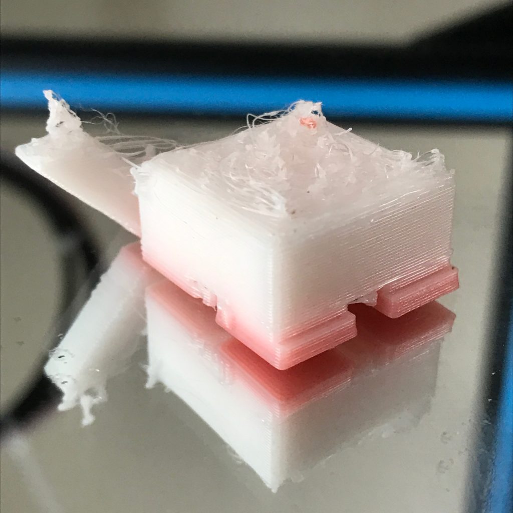
Failed attempt at Sainsmart TPU. Pink is from leftover red PLA in the extruder.
Sadly, it didn’t go particularly well. I had two failures in a row which were basically caused not such much by filament backing up in the tube, but by some back pressure causing the drive gear to stop getting traction on filament, and it just ceases to advance. This happened about 1cm into my first print, so I decided to up the temperature a bit to hopefully reduce the pressure and try again. That print failed almost immediately, about three layers in.
This caused me to abort my attempt for the day, and go off and scratch my head some more.
The obvious things to try would seem to be:
Additional temperature changes (higher, perhaps as high as 230?) but I think that higher temperatures also increase stringing and other undesirable problems.
Make sure that my drive gears are sharp and see if I can increase the tension on the drive spring.
Go even slower. Perhaps 15mm/s or even 10mm/s is reasonable.
February 20, 2019 | My Projects | By: Mark VandeWettering
I’ve had my Creality CR-10 for quite some time, and fairly early on I decided that I needed a bed leveling sensor. It wasn’t just because it was difficult to level the bed. The bed itself isn’t anywhere close to flat. Since the printer doesn’t know that, you have all sorts of problems with adhesion. To be honest, I’m not 100% certain I understand what math the bed leveling sensor does (it’s been on my list to understand). Let’s say that the bed has a 0.1mm crown in the center. Does this make the printer lay down a first layer which is 0.1mm thinner in the center? Or does it distort the print so that the first layer actually follows that contour and maintain a constant layer height?
I don’t know, but for now I don’t care. I just wanted it to work better when laying down the first layer to make sure that it stuck.
So I ordered the easiest bed level sensor solution I could find: the EZABL from TH3D. It’s not super cheap, but it’s convenient and didn’t require any soldering. They also have a version of the Marlin firmware available (the TH3D Unified Firmware) for download which is simple to configure for a wide variety of printers and directly supports their hardware.
And it works… okay.
About 9 times out of 10 I’ll get a good first layer. But every once in a while, the calibration will be twitchy, and something bad will happen. I think that ultimately it boils down to lack of repeatability. The sensor is a non-contact capacitive sensor and it appears to me (without scientific testing, and no slander intended) that the repeatability of probing (especially if I haven’t let the sensor heat up for quite a while) is pretty low. I’ll probably investigate that further, but in the mean time I thought it might be worthwhile to consider using a different type of sensor entirely: namely, a BLTouch, which uses a contact sensor. This has the advantage that whether I print on the aluminum bed, on tape, or on mirror tile I usually do, it will sense the actual surface that I’m printing on. That seems good to me, and the BLTouch has been pretty well regarded.
So I ordered one. Not super cheap either. You can get cheap clones on AliExpress, but I didn’t feel like waiting. With Prime I received mine yesterday.
The Bullseye duct…
So, I started thinking about installing it. I knew that I’d need a different mounting to put it on my printer. I had been using the PetsFang duct with the EZABL, so I thought about printing another one, but I noticed that they had updated a new design called the “Bullseye” which seemed to fix a few mechanical issues that I didn’t especially like with the original. It was also a modular design that enabled me to print holders for either the EZABL or the BLTouch, so that seemed like a good thing. I downloaded the parts and it took about six or seven hours to print all the parts.
Now, onto firmware and wiring…
And here’s where this project turned into a bit more of a headache than I would like. In a previous posting, I complained that the MELZI motherboard in the CR-10 used an ATmega1280 which has just 128K of flash. As it happens, the firmware that they’ve jammed into the CR-10 is really close to the limit. Thus, when you add new features to the firmware, you are often playing a game of “what features do I enable or disable to get it to fit.” This game is annoying. When I was using the TH3D Unified Firmware, they had done a lot of the work already, but the BLTouch is not (or badly) supported by recent versions of their firmware. The stock Marlin is a bit of a rats nest though, and while it does use platformio to compile (which I love), getting the configuration options set up properly is not a lot of fun.
But it gets worse…
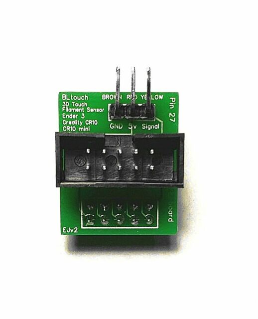
The BLTouch sensor has basically five pins which need to be wired to it, and the MELZI motherboard doesn’t direct support for it. The usual solution is to hijack the pin that provides the buzzer sound (pin 27) and hijack it to control the BLTouch. This requires a bit of wire snipping and soldering, or you could use a board which looks like this:
Pin 27 adapter board…
It’s a dumb little board whose purpose is to inject itself between the the connector for the display and the motherboard, and then breaks out the right pin to the side where you can easily attach the BLTouch. It’s got no active components on it at all: just a 10 pin IDC socket, with 10 header pins on the bottom and three 90 degree header pins on the side.
And they sell for a ridiculous amount of money (one seller on Amazon charges $20 for this little adapter board.) Absolutely insane. I’m pondering spending an afternoon to dust off my meager KiCad skills, draw up a quick PCB board, and have a bunch made by JLC PCB, as well as making the Gerber files made available so you can make your own. Stay tuned for that.
And I’ve found it difficult to find instructions that compile a reasonable version of Marlin for such a configuration. If I get time this weekend, I’ll try to work my way through it and document it so that any humble reader who stumbles across this can make one for himself.
Okay, that’s it for 3D printing this weekend. Have fun melting plastic.
I’m Mark VandeWettering, former senior technical director for Pixar Animation Studios, and (for the moment I’m a husband and father and grandfather. I like telescope making, radio, and all sorts of other things.
Latest Comments
I recall burning three or four weeks of a sabbatical getting Saccade.com on the air with Wordpress. So much tweaking…
I move my pretty useless blog to Hugo about 7 years ago, since I got frustrated at too many security…
Something I used to good effect for a while was a "Pocketmod". You take a single page, fold it a…
Bloat is a serious problem, to be sure, but I'm not aware of many modern programming languages that avoid it.…
I'm running static pages (Notepad++) and a couple instances of Wordpress, and an instance of dokuwiki, all on ubuntu on…


I recall burning three or four weeks of a sabbatical getting Saccade.com on the air with Wordpress. So much tweaking…