Monthly Archives: March 2015

Arduino? Perhaps we need OurDuino…

It’s no secret that I’ve been a fan of the Arduino. More than any other board, it’s got me into hacking little bits of hardware and programming in the small, and has been part of numerous projects that I’ve tinkered together, and others that I’ve helped mentor young people with. It’s a cute platform for a number of reasons:

  • They are widely available.
  • They are reasonably (well, sort of, more on this later) priced.
  • They are supported on all major platforms: Linux, Mac OS X and Windows
  • Their programming environment is a single, simple download.
  • Their programming libraries allow people to get started quickly.
  • There are a fair number of good shields to do hardware expansion.
  • And perhaps most importantly, they have a large community of people who develop and share code and techniques.

By my estimation, no other platform has this set of features.

Sadly, it appears that there is trouble in paradise. From this article on Hackaday:

Arduino LLC is the company founded by [Massimo Banzi], [David Cuartielles], [David Mellis], [Tom Igoe] and [Gianluca Martino] in 2009 and is the owner of the Arduino trademark and gave us the designs, software, and community support that’s gotten the Arduino where it is. The boards were manufactured by a spinoff company, Smart Projects Srl, founded by the same [Gianluca Martino]. So far, so good.

Things got ugly in November when [Martino] and new CEO [Federico Musto] renamed Smart Projects to Arduino Srl and registered arduino.org (which is arguably a better domain name than the old arduino.cc). Whether or not this is a trademark infringement is waiting to be heard in the Massachussetts District Court.

According to this Italian Wired article, the cause of the split is that [Banzi] and the other three wanted to internationalize the brand and license production to other firms freely, while [Martino] and [Musto] at the company formerly known as Smart Projects want to list on the stock market and keep all production strictly in the Italian factory.

Yikes.

I tend to side with Massimo for two reasons: one is, I’ve met Massimo at the San Mateo Maker Fair, and he was a nice, friendly, interesting guy. Second is that I think the value of the Arduino platform lies in design, rather than manufacturing. I’m willing to pay a premium for a product if it supports a company that provides excellent community support, and by and large I think Arduino LLC has done a good job. The motives of Arduino Srl seem much less community based, and more based upon maximizing the amount of money they can extract from the community.

I could be wrong, but that’s what it looks like to this observer.

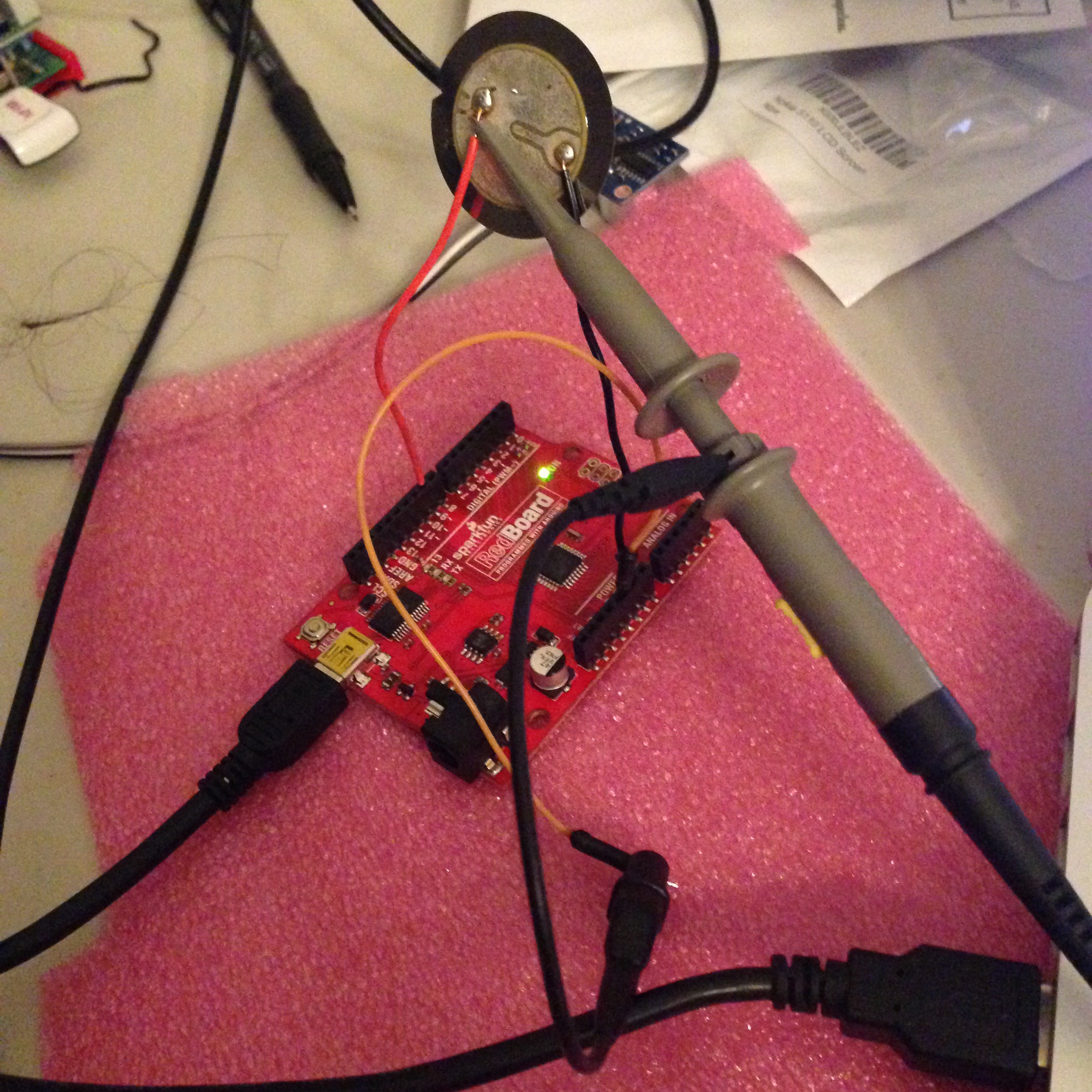
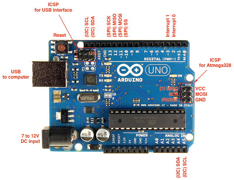
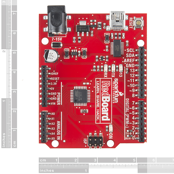
But the fact is, both sides seem to be (to paraphrase my good friend, Tom) “burning down the tree of awesome, only to sow the weeds of suck”. This kind of public spat expends a lot of the good will that the community has, and only serves to drive people to other platforms, or simply Chinese clones of the existing products. Because here’s the other thing: there is not a lot of secret sauce in the Arduino. It uses a very popular 8 bit processor, but one which is underpowered and overpriced relative to other 32 bit chips on the market. If you wanted to build an Arduino yourself, it’s really easy to do with only a few parts, and the guys at arduino.cc will even tell you how to do it. The optiboot bootloader is open source. You can program them with avr-gcc and avrdude, also open source products. If your company is not going to work to support the community as a whole, it’s awfully hard to justify spending $25 for an official Uno when you can buy a compatible Red Board from Sparkfun (a great company that does lots of great work with the community) for $20, or the Diavolino kit from Evil Mad Scientist for just $13, or Chinese clones assembled for $13 or less. And of course companies like Seeedstudio are manufacturing clones as well as new designs which share the footprint of the traditional Arduino, but use ARM chips (like the Arch, a $20 board that uses a NXP LPC11U24, a 32 bit ARM chip that runs at 48Mhz).

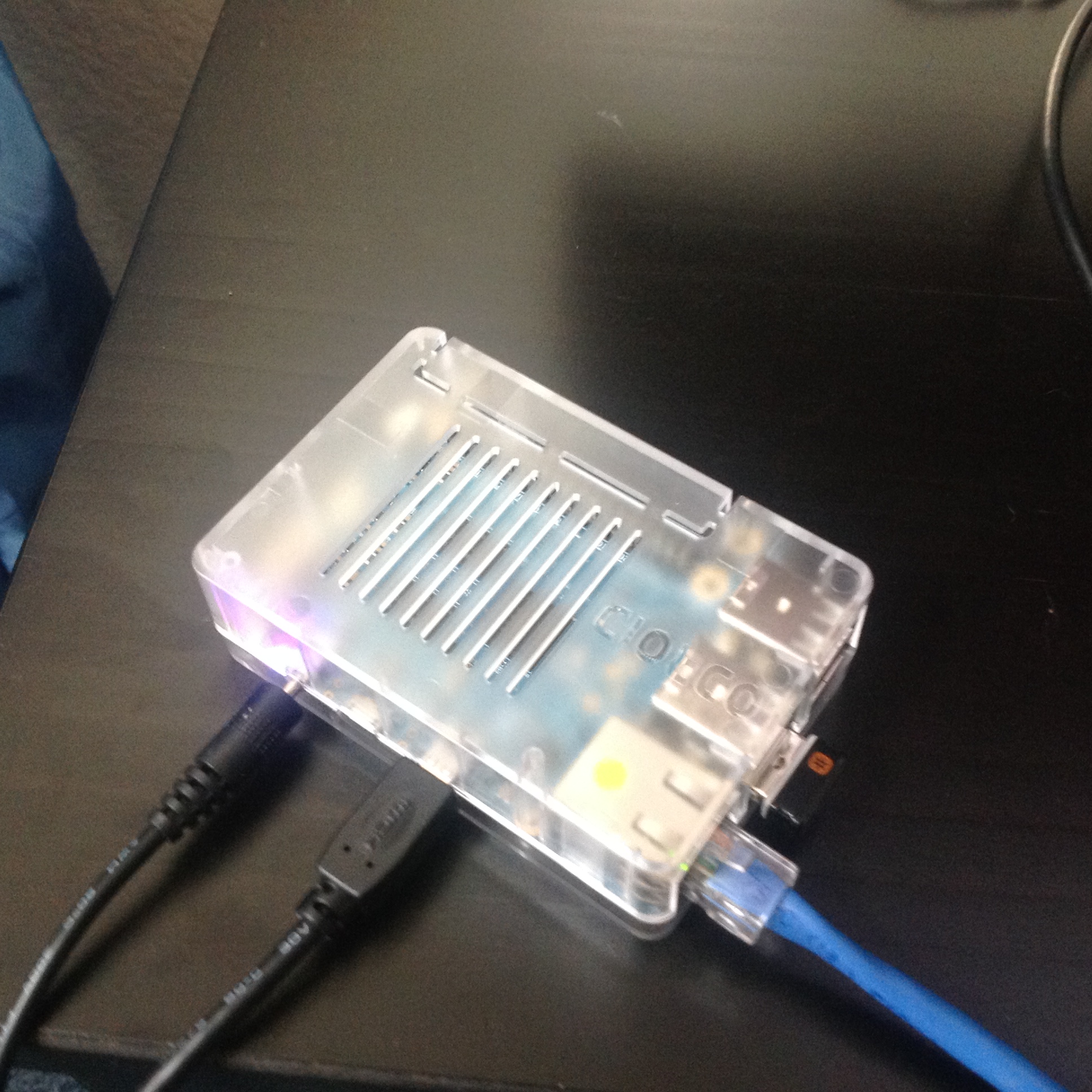
To be honest, I’ve been looking to find a better development platform. You don’t have to go very far to find more capable boards: consider the Raspberry Pi Model A+, which sells for a piddling $21.70. Or the WRTnode for just $25. Need even more power? The Raspberry Pi 2 is just $44.39 today on Amazon, and the intended price is lower. Or maybe the Beagle Bone Black for just $50 or so. There are LOTS of choices.

The fact is that while Arduino LLC and Arduino SRL argue it out, we can already build what they make, and China can already do it cheaper. Whoever wins, they better have a plan for how to woo us back, because it’s not 2006 anymore, and we’ll end up picking what we like, not what they decide to give us.

After all, to paraphrase the bard, “An Arduino by any other name is really just an ATMEGA328 with a boot loader.”

Minor tweaks to Arduino Morse Sketch…

Commenter Andy wanted a version of my classic code that could generate a tone instead of just blinking an LED. I mentioned that I had done this before, but frankly couldn’t find the source code, so I modified my existing program to implement the simplest possible tone: a simple square wave.

Rather than using a speaker, I wired up a little piezo element which I had soldered a couple of leads onto my junk pile. These disks are terrible at reproducing low frequencies and have strong resonances, but for this purpose, it was convenient. You can substitute a speaker if you like. It’s probably a good idea to use a little drive transistor with an 8 ohm speaker to provide more drive: you can see the basic idea here. It is nominally targeted toward mbed microcontrollers, but nothing about it is specific to those. Anyway, I hooked the positive lead of the element up to pin 9, and the negative lead to ground.

IMG_5699

I also hooked up my oscilloscope so I could verify that the tone was coming out at the proper frequency. Indeed, it appears that it works just fine.

IMG_5697

Additionally, I made a few other small changes to my program. The prior version stored the static table in RAM, which is wasteful of a hundred or so bytes of RAM. It doesn’t sound like a lot, but there are only 2048 bytes of RAM available, so every little bit helps.

Addendum: If you want to generate nicer looking sine waves, you could do a lot worse than to use this circuit from Jason, NT7S which serves as a nice little oscillator. It’s a nice little Twin-T oscillator, followed by a very simple little amplifier. You could use an optocoupler in place of the key to drive it, or probably just key it with another 2N2222 or similar transistor.

Addendum2: If you want to go all out, a circuit like this one has a very pretty keying waveform.

[sourcecode lang=”cpp”]
//
// Simple Arduino Morse Beacon
// Written by Mark VandeWettering K6HX
// Email: k6hx@arrl.net
//
// This code is so trivial that I’m releasing it completely without
// restrictions. If you find it useful, it would be nice if you dropped
// me an email, maybe plugged my blog @ https://brainwagon.org or included
// a brief acknowledgement in whatever derivative you create, but that’s
// just a courtesy. Feel free to do whatever.
//
// At the request of Andy, I added support to use the Arduino Tone library
// to generate an audio signal (really just a square wave) at 700hz on
// pin 9 (can be any pin which supports PWM, on the Arduino Uno, those pins
// are 3, 5, 6, 9, 10 or 11, and are usually marked with a dash next to them).
//
// NOTE: the audio signals is just a square wave. It’s not got a great
// tone, and may click or chirp at the end. It’s mostly useful as a
// sidetone generator, and probably should not be fed into the mic input
// of a transmitter to send MCW.

// This defines the pin that will have the audio signal

const int sndPin = 9 ;

// Sound frequency (in Hz)
#define SND_FREQ (700)

// If you leave NOISY defined, the Arduino will print out each character
// as it is sent to the serial port. You might want to comment this out
// (put // at the start of the line) if you are especially cramped for
// memory, otherwise it doesn’t hurt to leave it in place, even if you
// don’t hook the serial port to anything.
//
// If NOISY is defined, then the size of the program is…
// Program: 4938 bytes (15.1% Full)
// (.text + .data + .bootloader)
//
// Data: 399 bytes (19.5% Full)
// (.data + .bss + .noinit)
//
// If NOISY isn’t defined
// Program: 2964 bytes (9.0% Full)
// (.text + .data + .bootloader)
//
// Data: 48 bytes (2.3% Full)
// (.data + .bss + .noinit)
//

#define NOISY

struct t_mtab { char c, pat; } ;

// Compared to my earlier version of this code, we can
// save some precious RAM by storing this constant table
// in flash memory.

const struct t_mtab morsetab[] PROGMEM = {
{‘.’, 106},
{‘,’, 115},
{‘?’, 76},
{‘/’, 41},
{‘A’, 6},
{‘B’, 17},
{‘C’, 21},
{‘D’, 9},
{‘E’, 2},
{‘F’, 20},
{‘G’, 11},
{‘H’, 16},
{‘I’, 4},
{‘J’, 30},
{‘K’, 13},
{‘L’, 18},
{‘M’, 7},
{‘N’, 5},
{‘O’, 15},
{‘P’, 22},
{‘Q’, 27},
{‘R’, 10},
{‘S’, 8},
{‘T’, 3},
{‘U’, 12},
{‘V’, 24},
{‘W’, 14},
{‘X’, 25},
{‘Y’, 29},
{‘Z’, 19},
{‘1’, 62},
{‘2’, 60},
{‘3’, 56},
{‘4’, 48},
{‘5’, 32},
{‘6’, 33},
{‘7’, 35},
{‘8’, 39},
{‘9’, 47},
{‘0’, 63}
} ;

#define N_MORSE (sizeof(morsetab)/sizeof(morsetab[0]))

#define SPEED (12)
#define DOTLEN (1200/SPEED)
#define DASHLEN (3*(1200/SPEED))

const int LEDpin = 13 ;

void
dash()
{
digitalWrite(LEDpin, HIGH) ; // turn on the LED
tone(sndPin, SND_FREQ) ; // and the sound output..
delay(DASHLEN);
digitalWrite(LEDpin, LOW) ; // then back off
noTone(sndPin) ; // and silence…
delay(DOTLEN) ;
}

void
dit()
{
digitalWrite(LEDpin, HIGH) ; // again, LED on…
tone(sndPin, SND_FREQ); // and sound…
delay(DOTLEN);
digitalWrite(LEDpin, LOW) ; // off…
noTone(sndPin) ; // quiet…
delay(DOTLEN);
}

void
send(char c)
{
unsigned int i ;
if (c == ‘ ‘) {
#ifdef NOISY
Serial.print(c) ;
#endif
delay(7*DOTLEN) ;
return ;
}
for (i=0; i<N_MORSE; i++) {
if (pgm_read_byte(&(morsetab[i].c)) == c) {
unsigned char p = pgm_read_byte(&(morsetab[i].pat)) ;
#ifdef NOISY
Serial.print(c) ;
#endif
while (p != 1) {
if (p & 1)
dash() ;
else
dit() ;
p = p / 2 ;
}
delay(2*DOTLEN) ;
return ;
}
}
/* if we drop off the end, then we send a space */
#ifdef NOISY
Serial.print("?") ;
#endif
}

void
sendmsg(const char *str)
{
while (*str)
send(*str++) ;
#ifdef NOISY
Serial.println("");
#endif
}

void setup() {
pinMode(LEDpin, OUTPUT) ;
pinMode(sndPin, OUTPUT) ;
#ifdef NOISY
Serial.begin(9600) ;
Serial.println("Simple Arduino Morse Beacon v1.0") ;
Serial.println("Written by Mark VandeWettering <brainwagon@gmail.com>") ;
Serial.println("Check out my blog @ https://brainwagon.org") ;
Serial.print("LED will blink on pin ");
Serial.println(LEDpin);
Serial.print("Sound will be generated on pin ");
Serial.println(sndPin);
Serial.println("") ;
#endif
}

void loop() {
sendmsg("K6HX/B CM87") ;

tone(sndPin, SND_FREQ) ;
delay(20000);
noTone(sndPin) ;
delay(3000) ;
}
[/sourcecode]

Minor tweak to my Hummingbird Camera…

One thing I didn’t realize when I setup the Raspberry Pi camera to monitor my humming bird feeder was that it has a bright red led which turns on when the camera is enabled. In most cases, this light isn’t a big deal, but I am pointing it out the window, so the reflection of it is kind of annoying. You can see it in my earlier pictures, but I didn’t realize what it was until later, when I got this picture:

07-20150328182635-01

Luckily, it’s easy to disable. Just edit the file /boot/config.txt, and add a line which looks like:

disable_camera_led=1

and then reboot. Voila. All is fixed. This might be handy if you wanted to setup a stealth security camera as well. Just noted here, so I don’t forget.

Motion Detecting Hummingbird Camera: Prototype

Prototype CameraI like to see hummingbirds. They seem completely incredible to me, like little hyper Swiss Watches, buzzing around the garden. I’ve seen a few of them in our yard, but I’ve been meaning to encourage them showing up more, so I recently installed a feeder. While the syrup level has gone down, I have never caught one actually feeding.

Of course, the way to solve this problem (as is true of all problems) is to apply technology! So, I quickly hacked together a little prototype camera that I could hang on my window and stare out at feeder. I’ve been thinking of doing this all week, and gotten proofing. In the end, I wasn’t getting anywhere, so this morning I decided on what I thought was the simplest possible prototype. I took one of my old Raspberry Pi’s, a DLINK powered USB hub to power it, and a Raspberry Pi camera, and taped them all in the cardboard box for an old laptop hard drive. My original idea was simply to duct tape it to the window facing the bird feeder, but a quick trial of this wasn’t promising: the duct tape kept relaxing, and the box was slowly drifting down. So, instead I got some wire and made a little hanger that would attach to two paperclips that I jammed in each side. It isn’t the greatest way to go, but it works.

I hung it from the top of the blinds in the kitchen, aimed it only very coarsely, and took my first picture by logging in and running raspistill. The aim isn’t very good, I only got the feeder at the edge, but this is just a prototype: if I start getting pictures of hummingbirds, I will refine the design/aim, and probably mount the camera outside so I can be a bit closer.

mingbird Feeder Prototype

Of course all you see are the drought stricken side of my hill, but if I get any pictures of birds, I’ll be posting them soon.

Addendum: I wandered outside as a quick test of the camera. While I am bigger than a hummingbird, I didn’t have any problem tripping the camera. I am concerned that the small, fast motion of a hummingbird may not be sufficient to trip the camera, but we shall see.

01-20150328135843-01i

A couple of additional words on the software. I use the “motion-mmal” program, a port of the popular “motion” program that is widely used on Linux with conventional webcams, but has been extended to use the Raspberry Pi camera, which are both high quality and inexpensive. The way I have this configured is that it does motion detection on a downresolution version of the video feed, and when it detects motion, it dumps the frame with the biggest difference to a local disk. Eventually, I may try to get it to capture video, and/or upload it automatically to google drive like I have done before for my cat camera. More later.

Addendum2: Huzzah! Within an hour of setting this camera up, I got my first picture! I guess it works. I’ll have to get it aimed a bit better and see how often I can catch birds, and maybe try to set it up to do motion capture too, not just stills.

04-20150328144545-02

Tiny BASIC on a Tiny Display…

IMG_5694Early in 2012, I posted a small version of Tiny BASIC that I had adapted to run on the Arduino. It is based upon code which was written by Mike Field, and based upon an earlier version of TinyBasic for the 68000 written by Gordon Brandly, which owes its roots to Palo Alto Tiny BASIC, written all the way back in 1976 as one of the first examples of a free software project.

I had done a couple of extensions to that code to include simple commands to read and write digital and analog I/O pins, implement simple delays, and even generate simple tones. But then the project languished. Tonight, I dusted that code off and made a number of improvements.

First of all, the original program didn’t have very much memory to store programs. This is due largely to the fact that the Arduino Uno has only 2048 bytes of RAM to use for any purpose at all, so every byte is important. What I realized in staring at the code tonight was that a significant number of bytes (well, significant in this context) number of bytes were used to store some static data tables that defined the keywords and functions available to the interpreter. By changing those to “const” tables, I could move them to be stored in the flash (read-only) memory, and free up a couple hundred additional bytes of storage. That may not sound like a lot, but every little bit helps. Now when the system boots, it has 1146 bytes of memory to store programs.

Next, I thought it would be fun to use the OLED display that I’ve been tinkering with to act as an output display. I did a little quick math: I liked an 8×13 font for display, so that meant I could just get 4 lines of 16 characters on the display. That meant that I’d need 64 bytes of ram to store the contents, but that should be a small price to pay. I wrote up a new “outputchar” routine that would deposit printed characters at the the cursor location in the memory buffer, and then increment the cursor position, and handle scrolling. Refreshing the LED screen is not very fast, since it is occurring over the I2C bus, so I thought about a couple ways to “batch” the printing of individual characters, and only refresh the screen when a bunch of output has occurred, only when the screen was “dirty”, and when a time interval had passed. It took me a couple of tries to get this right, but it seems like it worked.

I filmed a short demo of the system working. The keyboard input is still coming from the serial monitor, but display is going to the OLED.


I’d be happy to release the code in a few days after I tinker a bit more. Right now, command line editing is a bit rough, and I’d like to get that working better.

Addendum: This code (the original authors, not mine) has served as the basis for additional versions, some more capable than mine. TinyBasicPlus includes commands to save and chain programs from the internal EEPROM, and store them to SD cards. Very neat.

Using the Parallax PING))) ultrasonic distance sensor

I intended to play around with some of the NRF24L01 radio modules I have around, but my brain didn’t feel up to it after a day of debugging. So, instead i dusted off a Parallax PING))) sensor that I’ve had around for a long time. I thought it might be fun to see if I could use the OLED display to display the distance measured by the sensor. While watching Agents of Shield, I came up with the following tiny bit of code, demo’ed below.


[sourcecode lang=”cpp”]
#include "U8glib.h"

U8GLIB_SSD1306_128X64 u8g(U8G_I2C_OPT_NONE);

// _
// ___ (_)__ ___ _
// / _ \/ / _ \/ _ `/
// / .__/_/_//_/\_, /
// /_/ /___/
//
// A simple rangefinder program using the Parallax PING sensor
// Writes display out to my tiny OLED display…

const int pingPin = 7 ;

char dbuf[10] ;

void
draw()
{
u8g.setDefaultBackgroundColor();
u8g.drawBox(0, 0, 128, 64);
u8g.setDefaultForegroundColor();
u8g.setFont(u8g_font_10x20);
u8g.drawStr(14, 42, dbuf);
u8g.drawStr(94, 42, "cm");
}

void
setup()
{
Serial.begin(9600);
}

void
loop()
{
long duration ;

pinMode(pingPin, OUTPUT);
digitalWrite(pingPin, LOW); // Make sure we drive the pin low…
delayMicroseconds(2);
digitalWrite(pingPin, HIGH); // Pulse high for 5us
delayMicroseconds(5);
digitalWrite(pingPin, LOW); // Finish the pulse…

pinMode(pingPin, INPUT); // Get ready to read…
duration = pulseIn(pingPin, HIGH); // Wait for the echo pulse to drop back to low

// The speed of sound is 29 us per cm… j

float cm = duration / (29. * 2.) ;
dtostrf(cm, 8, 2, dbuf) ;

u8g.firstPage() ;
do {
draw() ;
} while (u8g.nextPage()) ;
}
[/sourcecode]

Addendum: I’ve been snapping short videos with the Vine app, and then posting them to Twitter and Facebook. Irritatingly, these don’t seem to actually play properly when I embed them back in my website. I’ll figure out a better workflow next time.

Addendum2: Goofing around a little, it appeared that this sensor worked out until about 70cm or so, and then snaps to 340cm. Not sure what that is about: the sensor should behave more accurately than that. I’ll experiment more tomorrow. I should also note that these Parallax sensors are fairly pricey: list price is almost $30. I like the Parallax guys a lot, but that’s pretty spendy. You can get much cheaper modules on Ebay, with costs as low as around $1.50. I haven’t got any of these, but they are worth trying, although various sources on the web suggest that you might get what you pay for. Try googling for “HC-SR04” for more information.

My version of minilife2 for the Arduino…

Without a lot more explanation, I did a bit more work on my implementation of Conway’s life, reducing the overhead so I can implement the full 128×64 bit resolution of the OLED display. I also hardcoded an initial pattern: the classic Gosper glider gun. It runs at about 1.625 frames/second, so a new glider is emitted every 18 seconds or so. Eventually, they wrap around and destroy the glider gun by colliding with it. I can think of a few more optimizations that are easy, but I doubt they are very important.


[sourcecode lang=”cpp”]
#include "U8glib.h"

U8GLIB_SSD1306_128X64 u8g(U8G_I2C_OPT_NONE);

#define XSIZE (128)
#define XMASK (127)
#define XSIZE_UINT8 (XSIZE/8)
#define YSIZE (64)
#define YMASK (63)

// We use the extra lines as buffer space…
uint8_t c[YSIZE][XSIZE_UINT8] ;

#define MODX(x) (((x)+XSIZE)&XMASK)
#define MODY(y) (((y)+YSIZE)&YMASK)

#define ISSET(a, x) \
(a[MODX(x)>>3] & (0x1<<(MODX(x)&7)))

#define SET(a, x) \
a[MODX(x)>>3] |= (0x1<<(MODX(x)&7))

#define SETXY(a, x, y) \
a[y][x>>3] |= (0x1<<((x)&7))

#define CLR(a, x) \
a[MODX(x)>>3] &= ~(0x1<<(MODX(x)&7))

void
initrandom()
{
int i, j ;
for (j=0; j<YSIZE; j++)
for (i=0; i<XSIZE_UINT8; i++)
c[j][i] = random(256) ;
}

void
initgun()
{
memset(c, 0, sizeof(c)) ;
SETXY(c, 70, 28); SETXY(c, 68, 29); SETXY(c, 70, 29); SETXY(c, 58, 30);
SETXY(c, 59, 30); SETXY(c, 66, 30); SETXY(c, 67, 30); SETXY(c, 80, 30);
SETXY(c, 81, 30); SETXY(c, 57, 31); SETXY(c, 61, 31); SETXY(c, 66, 31);
SETXY(c, 67, 31); SETXY(c, 80, 31); SETXY(c, 81, 31); SETXY(c, 46, 32);
SETXY(c, 47, 32); SETXY(c, 56, 32); SETXY(c, 62, 32); SETXY(c, 66, 32);
SETXY(c, 67, 32); SETXY(c, 46, 33); SETXY(c, 47, 33); SETXY(c, 56, 33);
SETXY(c, 60, 33); SETXY(c, 62, 33); SETXY(c, 63, 33); SETXY(c, 68, 33);
SETXY(c, 70, 33); SETXY(c, 56, 34); SETXY(c, 62, 34); SETXY(c, 70, 34);
SETXY(c, 57, 35); SETXY(c, 61, 35); SETXY(c, 58, 36); SETXY(c, 59, 36);
}

void
setup()
{
#ifdef TIME_ME
Serial.begin(9600) ;
#endif

randomSeed(analogRead(A0));
initgun() ;
}

void
draw()
{
u8g.setDefaultBackgroundColor() ;
u8g.drawBox(0, 0, 128, 64) ;
u8g.setDefaultForegroundColor() ;
u8g.drawXBM(0, 0, XSIZE, YSIZE, (const uint8_t *) c) ;
}

void
line(const uint8_t *a, const uint8_t *b, const uint8_t *c,
uint8_t *out)
{
int i ;
for (i=0; i<XSIZE; i++) {
int sum = 0 ;
if (ISSET(a, i-1)) sum ++ ;
if (ISSET(a, i )) sum ++ ;
if (ISSET(a, i+1)) sum ++ ;
if (ISSET(b, i-1)) sum ++ ;
if (ISSET(b, i+1)) sum ++ ;
if (ISSET(c, i-1)) sum ++ ;
if (ISSET(c, i )) sum ++ ;
if (ISSET(c, i+1)) sum ++ ;

if (ISSET(b, i)) {
if (sum == 2 || sum == 3)
SET(out, i) ;
else
CLR(out, i) ;
} else {
if (sum == 3)
SET(out, i) ;
else
CLR(out, i) ;
}
}
}

void
loop()
{
int j, op ;
uint8_t obuf[2][XSIZE_UINT8] ;
uint8_t otmp[XSIZE_UINT8] ;

#ifdef TIME_ME
unsigned long time_start, time_stop ;

time_start = millis() ;
#endif

line(c[YSIZE-1], c[0], c[1], obuf[0]) ;
line(c[0], c[1], c[2], obuf[1]) ;
op = 0 ;

// We need this for the wrap around.

memcpy(otmp, c[0], XSIZE_UINT8) ;

for (j=2; j<YSIZE-1; j++) {
memcpy(c[j-2], obuf[op], XSIZE_UINT8) ;
line(c[MODY(j-1)], c[j], c[MODY(j+1)], obuf[op]) ;
op = 1 – op ;
}

// We still have three lines we need to copy back…
// And one more buffer to compute with line()

memcpy(c[YSIZE-3], obuf[op], XSIZE_UINT8) ;
line(c[YSIZE-2], c[YSIZE-1], otmp, obuf[op]) ;
op = 1 – op ;
memcpy(c[YSIZE-2], obuf[op], XSIZE_UINT8) ;
op = 1 – op ;
memcpy(c[YSIZE-1], obuf[op], XSIZE_UINT8) ;

// compute one generation..

u8g.firstPage() ;
do {
draw() ;
} while (u8g.nextPage()) ;

#ifdef TIME_ME
time_stop = millis() ;

Serial.print(time_stop – time_start) ;
Serial.println() ;
#endif
}
[/sourcecode]

A few more notes on my implementation of Conway’s Life…

I received a couple of email and twitter queries about various aspects of the code, so I thought I would add a followup to yesterday’s post.

First of all, I received a query as to whether it was “open source”. Frankly, the code is so minimal and so obvious I didn’t even consider it worthy of protection from any license. Consider it in the public domain. I do appreciate it when people who use this code give a nod back to my website as the origin of the code, but it’s not mandatory.

Seriously. It’s not a big deal.

Next, realize that I wrote the code in just a few minutes (less than thirty). It’s written in just about the most obvious way I could conceive. I really was just looking at a way to test my understanding of the U8glib library, and this seemed like a good way to go. There are a number of ways the code could be improved.

First, this implementation doesn’t use the full resolution of the 128×64 display: it only uses 96×64. The reason is quite simple: the way the code is written, it needs to maintain 2 buffers (the “current” and “next” arrays) each of which hold 128×64 bits. If you multiply out 128x64x2 and divide by 8 to get the number of bits needed, you’ll come up with 2048: coincidently, exactly the same amount of RAM in an ATMega328. But you’ll need some extra memory to hold temporary variables, buffers used by the U8glib, the stack for subroutine calls, etc… Trimming the resolution back to 96×64 provides enough space to actually run. But we could actually use the full resolution by being slightly more clever: instead of having two full size arrays, we could do more of the updates “in place”, and only buffer a couple of extra lines to hold out temporary values before we overwrite them. I have the code in my head, but a few odd details about it aren’t worked out yet, I hope to have nearly as simple an implementation worked out today some time. Stay tuned.

Second, it’s slow. Doing 8 independent bit lookups in the array, the increments, and the compares? It’s a straightforward implementation, but not a fast one. In particular, the shift operations on every pixel lookup are probably really a bad idea on the Atmel AVR: these chips don’t include a barrel shifter, so to shift by 7 takes 7 cycles. We could probably factor out a lot of these calculations with some work. It’s possible to use techniques that can process all the bits inside a given word “in parallel” by implementing bitwise arithmetic, but since the AVR is only an 8 bit processor, the gains are less than they would be on a 32 bit processor, and handling all the edge cases is kind of a nuisance. I remember doing this back in my college days, but I’d have to work out all the details again. You can look at this article from StackOverflow to get some hints and pointers to other implementations. Some of the ideas are good, some not.

Third: the display is really, really tiny. It might be fun to use the builtin scaling of the U8G driver to magnify it by two. Then, of course, we’ll only need to do 64×32, which should run around 4x as fast, and should be easier to see. It will also use a lot less memory, which makes it more useful as a module in (say) another program like a DIY watch.

Lastly, I was told that initializing the random number generator in this way would work, but it seems to generate the same seed each time. I’ll have to figure out a better way to initialize the seed on RESET.

Stay tuned for an improved version.

Tiny Implementation of Conway’s Life…

I had a few minutes, so I thought I’d try making a graphics demo that runs on the tiny little 0.96″ OLED display I mentioned last week. One of the first programs I ever wrote was an implementation of Conway’s Game of Life, having learned about it from Martin Gardner’s Mathematical Games column in Scientific American. I remember that on my old Atari 400, it took a couple of seconds at least per generation, at a resolution of just 40×20 or so. Because of the limited memory (and small size of the display) I decided a 96×64 resolution. There is just enough memory to handle two full sized bit buffers. With a bit more work, I could make it work at the full resolution of the OLED display, but you need to do some of the updates in place, which makes it a bit harder.

[sourcecode lang=”cpp”]
//
// a tiny implementation of Conway’s Life
// written by Mark VandeWettering (brainwagon@gmail.com)
// https://brainwagon.org
//

#include "U8glib.h"

#define XSIZE (128-32)
#define XSIZE_UINT8 (XSIZE/8)
#define YSIZE (64)

uint8_t current[YSIZE][XSIZE_UINT8] ;
uint8_t next[YSIZE][XSIZE_UINT8] ;

#define MODX(x) (((x)+XSIZE)%XSIZE)
#define MODY(y) (((y)+YSIZE)%YSIZE)

#define ISSET(a, x, y) \
(a[MODY(y)][MODX(x)/8] & (0x1<<(MODX(x)&7)))

#define SET(a, x, y) \
a[MODY(y)][MODX(x)/8] |= (0x1<<(MODX(x)&7))

U8GLIB_SSD1306_128X64 u8g(U8G_I2C_OPT_NONE);

void
init()
{
int i, j ;
for (j=0; j<YSIZE; j++)
for (i=0; i<XSIZE_UINT8; i++)
current[j][i] = random(256) ;
}

void
setup()
{
randomSeed(analogRead(0));
init() ;
}

void
draw()
{
u8g.setDefaultBackgroundColor() ;
u8g.drawBox(0, 0, 128, 64) ;
u8g.setDefaultForegroundColor() ;
u8g.drawXBM(16, 0, XSIZE, YSIZE, (const uint8_t *) next) ;
}

void
loop()
{
int i, j ;

memset((void *) next, 0, sizeof(next)) ;
for (j=0; j<YSIZE; j++) {
for (i=0; i<XSIZE; i++) {
int sum = 0 ;
if (ISSET(current, i-1, j-1)) sum ++ ;
if (ISSET(current, i , j-1)) sum ++ ;
if (ISSET(current, i+1, j-1)) sum ++ ;
if (ISSET(current, i-1, j )) sum ++ ;
if (ISSET(current, i+1, j )) sum ++ ;
if (ISSET(current, i-1, j+1)) sum ++ ;
if (ISSET(current, i , j+1)) sum ++ ;
if (ISSET(current, i+1, j+1)) sum ++ ;

if (ISSET(current, i, j)) {
if (sum == 2 || sum == 3)
SET(next, i, j) ;
} else {
if (sum == 3)
SET(next, i, j) ;
}
}
}

memcpy((void *) current, (void *) next, sizeof(current)) ;

u8g.firstPage() ;
do {
draw() ;
} while (u8g.nextPage()) ;
}
[/sourcecode]

It works! It initializes the display to random values, and then runs Life. If the display gets boring, just hit the result button….


Discovered a new tool for embedded development: platformio

I’m pretty old school when it comes to development. To me, writing code is something I like to do with vi (the editor that I learned three decades ago) and compile with Makefiles, especially for code that I do myself. In general, I prefer to do my development on either Linux or Mac OS too, so portable tools are my favorite. Increasingly, people have come to rely on complex development environments, many of which include code wizards that generate lots of the boiler plate needed to create applications, complex syntax coloring, and engines to refactor code. These environments are often significantly different from one another, are closed source, or rely on older versions of open source tools (like plugins for eclipse).

This seemed doubly true for this little Freescale development board that has been sitting unused since I purchased it at the last (or was it the one before that) Maker Faire. It is supposedly part of the “mbed” family of dev boards, which is supposed to make development across a variety of similar boards simple. But the reality is a dizzying array of odd products, including a web based IDE that just annoyed and confounded me. So, the board mostly sat unused. I did mention it in my “bucket o’ dev boards” video a couple weeks ago, and I thought “there must be a better way”.

Rather than toil away on my own, I tossed the question to my twitter followers:


Within minutes, @ukscone responded with this suggestion:


I had never heard of platformio, but I quickly read over the quickstart, and was impressed. Basically it’s a fairly simple utility called (appropriately enough) platformio, written in Python, and portable to Windows, Mac OS X and Linux. Compiled within it is knowledge of a large number of supported boards. You can get a list of supported boards by typing “platformio boards”, and you’ll get the output.

Platform: atmelavr
---------------------------------------------------------------------------
Type                  MCU            Frequency  Flash   RAM    Name
---------------------------------------------------------------------------
flora8                atmega32u4     8Mhz      28Kb    2Kb    Adafruit Flora
trinket3              attiny85       8Mhz      8Kb     512B   Adafruit Trinket 3V/8MHz
trinket5              attiny85       16Mhz     8Kb     512B   Adafruit Trinket 5V/16MHz
btatmega168           atmega168      16Mhz     14Kb    1Kb    Arduino BT ATmega168
btatmega328           atmega328p     16Mhz     28Kb    2Kb    Arduino BT ATmega328
diecimilaatmega168    atmega168      16Mhz     14Kb    1Kb    Arduino Duemilanove or Diecimila ATmega168
diecimilaatmega328    atmega328p     16Mhz     30Kb    2Kb    Arduino Duemilanove or Diecimila ATmega328
esplora               atmega32u4     16Mhz     28Kb    2Kb    Arduino Esplora
ethernet              atmega328p     16Mhz     31Kb    2Kb    Arduino Ethernet
fio                   atmega328p     8Mhz      30Kb    2Kb    Arduino Fio
leonardo              atmega32u4     16Mhz     28Kb    2Kb    Arduino Leonardo
megaADK               atmega2560     16Mhz     248Kb   8Kb    Arduino Mega ADK
megaatmega1280        atmega1280     16Mhz     124Kb   8Kb    Arduino Mega or Mega 2560 ATmega1280
megaatmega2560        atmega2560     16Mhz     248Kb   8Kb    Arduino Mega or Mega 2560 ATmega2560 (Mega 2560)
micro                 atmega32u4     16Mhz     28Kb    2Kb    Arduino Micro
miniatmega168         atmega168      16Mhz     14Kb    1Kb    Arduino Mini ATmega168
miniatmega328         atmega328p     16Mhz     28Kb    2Kb    Arduino Mini ATmega328
atmegangatmega168     atmega168      16Mhz     14Kb    1Kb    Arduino NG or older ATmega168
atmegangatmega8       atmega8        16Mhz     7Kb     1Kb    Arduino NG or older ATmega8
nanoatmega168         atmega168      16Mhz     14Kb    1Kb    Arduino Nano ATmega168
nanoatmega328         atmega328p     16Mhz     30Kb    2Kb    Arduino Nano ATmega328
pro8MHzatmega168      atmega168      8Mhz      14Kb    1Kb    Arduino Pro or Pro Mini ATmega168 (3.3V, 8 MHz)
pro16MHzatmega168     atmega168      16Mhz     14Kb    1Kb    Arduino Pro or Pro Mini ATmega168 (5V, 16 MHz)
pro8MHzatmega328      atmega328p     8Mhz      30Kb    2Kb    Arduino Pro or Pro Mini ATmega328 (3.3V, 8 MHz)
pro16MHzatmega328     atmega328p     16Mhz     30Kb    2Kb    Arduino Pro or Pro Mini ATmega328 (5V, 16 MHz)
robotControl          atmega32u4     16Mhz     28Kb    2Kb    Arduino Robot Control
robotMotor            atmega32u4     16Mhz     28Kb    2Kb    Arduino Robot Motor
uno                   atmega328p     16Mhz     31Kb    2Kb    Arduino Uno
yun                   atmega32u4     16Mhz     28Kb    2Kb    Arduino Yun
digispark-tiny        attiny85       16Mhz     5Kb     512B   Digispark (Default - 16 MHz)
digispark-pro32       attiny167      16Mhz     14Kb    512B   Digispark Pro (16 MHz) (32 byte buffer)
digispark-pro64       attiny167      16Mhz     14Kb    512B   Digispark Pro (16 MHz) (64 byte buffer)
digispark-pro         attiny167      16Mhz     14Kb    512B   Digispark Pro (Default 16 MHz)
engduinov1            atmega32u4     8Mhz      28Kb    2Kb    Engduino 1
engduinov2            atmega32u4     8Mhz      28Kb    2Kb    Engduino 2
engduinov3            atmega32u4     8Mhz      28Kb    2Kb    Engduino 3
lilypadatmega168      atmega168      8Mhz      14Kb    1Kb    LilyPad Arduino ATmega168
lilypadatmega328      atmega328p     8Mhz      30Kb    2Kb    LilyPad Arduino ATmega328
LilyPadUSB            atmega32u4     8Mhz      28Kb    2Kb    LilyPad Arduino USB
168pa16m              atmega168p     16Mhz     15Kb    1Kb    Microduino Core (Atmega168PA@16M,5V)
168pa8m               atmega168p     8Mhz      15Kb    1Kb    Microduino Core (Atmega168PA@8M,3.3V)
328p16m               atmega328p     16Mhz     31Kb    2Kb    Microduino Core (Atmega328P@16M,5V)
328p8m                atmega328p     8Mhz      31Kb    2Kb    Microduino Core (Atmega328P@8M,3.3V)
32u416m               atmega32u4     16Mhz     28Kb    2Kb    Microduino Core USB (ATmega32U4@16M,5V)
1284p16m              atmega1284p    16Mhz     127Kb   16Kb   Microduino Core+ (ATmega1284P@16M,5V)
1284p8m               atmega1284p    8Mhz      127Kb   16Kb   Microduino Core+ (ATmega1284P@8M,3.3V)
644pa16m              atmega644p     16Mhz     63Kb    4Kb    Microduino Core+ (Atmega644PA@16M,5V)
644pa8m               atmega644p     8Mhz      63Kb    4Kb    Microduino Core+ (Atmega644PA@8M,3.3V)
panStampAVR           atmega328p     8Mhz      31Kb    2Kb    PanStamp AVR
protrinket3ftdi       atmega328p     16Mhz     28Kb    2Kb    Pro Trinket 3V/12MHz (FTDI)
protrinket3           atmega328p     12Mhz     28Kb    2Kb    Pro Trinket 3V/12MHz (USB)
protrinket5ftdi       atmega328p     16Mhz     28Kb    2Kb    Pro Trinket 5V/16MHz (USB)
protrinket5           atmega328p     16Mhz     28Kb    2Kb    Pro Trinket 5V/16MHz (USB)
raspduino             atmega328p     16Mhz     30Kb    2Kb    Raspduino

Platform: atmelsam
---------------------------------------------------------------------------
Type                  MCU            Frequency  Flash   RAM    Name
---------------------------------------------------------------------------
due                   at91sam3x8e    84Mhz     512Kb   32Kb   Arduino Due (Programming Port)
dueUSB                at91sam3x8e    84Mhz     512Kb   32Kb   Arduino Due (USB Native Port)
digix                 at91sam3x8e    84Mhz     512Kb   28Kb   Digistump DigiX
sainSmartDue          at91sam3x8e    84Mhz     512Kb   32Kb   SainSmart Due (Programming Port)
sainSmartDueUSB       at91sam3x8e    84Mhz     512Kb   32Kb   SainSmart Due (USB Native Port)

Platform: freescalekinetis
---------------------------------------------------------------------------
Type                  MCU            Frequency  Flash   RAM    Name
---------------------------------------------------------------------------
IBMEthernetKit        mk64fn1m0vll12 120Mhz    1024Kb  256Kb  Ethernet IoT Starter Kit
frdm_k20d50m          mk20dx128vlh5  48Mhz     128Kb   16Kb   Freescale Kinetis FRDM-K20D50M
frdm_k22f             mk22fn512vlh12 120Mhz    512Kb   128Kb  Freescale Kinetis FRDM-K22F
frdm_k64f             mk64fn1m0vll12 120Mhz    1024Kb  256Kb  Freescale Kinetis FRDM-K64F
frdm_kl05z            mkl05z32vfm4   48Mhz     32Kb    4Kb    Freescale Kinetis FRDM-KL05Z
frdm_kl25z            mkl25z128vlk4  48Mhz     128Kb   16Kb   Freescale Kinetis FRDM-KL25Z
frdm_kl46z            mkl46z256vll4  48Mhz     256Kb   32Kb   Freescale Kinetis FRDM-KL46Z

Platform: nordicnrf51
---------------------------------------------------------------------------
Type                  MCU            Frequency  Flash   RAM    Name
---------------------------------------------------------------------------
wallBotBLE            nrf51822       16Mhz     128Kb   16Kb   JKSoft Wallbot BLE
nrf51_dk              nrf51822       32Mhz     256Kb   32Kb   Nordic nRF51-DK
nrf51_dongle          nrf51822       32Mhz     256Kb   32Kb   Nordic nRF51-Dongle
nrf51_mkit            nrf51822       16Mhz     128Kb   16Kb   Nordic nRF51822-mKIT
redBearLabBLENano     nrf51822       16Mhz     256Kb   16Kb   RedBearLab BLE Nano
redBearLab            nrf51822       16Mhz     256Kb   16Kb   RedBearLab nRF51822
seeedTinyBLE          nrf51822       16Mhz     256Kb   16Kb   Seeed Tiny BLE
hrm1017               nrf51822       16Mhz     256Kb   16Kb   Switch Science mbed HRM1017

Platform: nxplpc
---------------------------------------------------------------------------
Type                  MCU            Frequency  Flash   RAM    Name
---------------------------------------------------------------------------
blueboard_lpc11u24    lpc11u24       48Mhz     32Kb    8Kb    BlueBoard-LPC11U24
dipcortexm0           lpc11u24       50Mhz     32Kb    8Kb    DipCortex M0
lpc11u35              lpc11u35       48Mhz     64Kb    10Kb   EA LPC11U35 QuickStart Board
lpc4088_dm            lpc4088        120Mhz    512Kb   96Kb   EA LPC4088 Display Module
lpc4088               lpc4088        120Mhz    512Kb   96Kb   EA LPC4088 QuickStart Board
lpc1549               lpc1549        72Mhz     256Kb   36Kb   LPCXpresso1549
mbuino                lpc11u24       48Mhz     32Kb    8Kb    Outrageous Circuits mBuino
seeeduinoArchPro      lpc1768        96Mhz     512Kb   32Kb   Seeeduino-Arch-Pro
lpc11u35_501          lpc11u35       48Mhz     64Kb    10Kb   TG-LPC11U35-501
lpc1114fn28           lpc1114fn28    48Mhz     32Kb    4Kb    mbed LPC1114FN28
lpc11u24              lpc11u24       48Mhz     32Kb    8Kb    mbed LPC11U24
lpc1768               lpc1768        96Mhz     512Kb   32Kb   mbed LPC1768
ubloxc027             lpc1768        96Mhz     512Kb   32Kb   u-blox C027

Platform: ststm32
---------------------------------------------------------------------------
Type                  MCU            Frequency  Flash   RAM    Name
---------------------------------------------------------------------------
disco_f334c8          stm32f334c8t6  72Mhz     64Kb    16Kb   32F3348DISCOVERY
disco_f401vc          stm32f401vct6  84Mhz     256Kb   64Kb   32F401CDISCOVERY
disco_f429zi          stm32f429zit6  180Mhz    2048Kb  256Kb  32F429IDISCOVERY
nucleo_f030r8         stm32f030r8t6  48Mhz     64Kb    8Kb    ST Nucleo F030R8
nucleo_f070rb         stm32f070rbt6  48Mhz     128Kb   16Kb   ST Nucleo F070RB
nucleo_f072rb         stm32f072rbt6  48Mhz     128Kb   16Kb   ST Nucleo F072RB
nucleo_f091rc         stm32f091rct6  48Mhz     256Kb   32Kb   ST Nucleo F091RC
nucleo_f103rb         stm32f103rbt6  72Mhz     128Kb   20Kb   ST Nucleo F103RB
nucleo_f302r8         stm32f302r8t6  72Mhz     64Kb    16Kb   ST Nucleo F302R8
nucleo_f303re         stm32f303ret6  72Mhz     512Kb   64Kb   ST Nucleo F303RE
nucleo_f334r8         stm32f334r8t6  72Mhz     64Kb    16Kb   ST Nucleo F334R8
nucleo_f401re         stm32f401ret6  84Mhz     512Kb   96Kb   ST Nucleo F401RE
nucleo_f411re         stm32f411ret6  100Mhz    512Kb   128Kb  ST Nucleo F411RE
nucleo_l053r8         stm32l053r8t6  48Mhz     64Kb    8Kb    ST Nucleo L053R8
nucleo_l152re         stm32l152ret6  32Mhz     512Kb   80Kb   ST Nucleo L152RE
disco_f051r8          stm32f051r8t6  48Mhz     64Kb    8Kb    STM32F0DISCOVERY
disco_f303vc          stm32f303vct6  72Mhz     256Kb   48Kb   STM32F3DISCOVERY
disco_f407vg          stm32f407vgt6  168Mhz    1024Kb  128Kb  STM32F4DISCOVERY
disco_l152rb          stm32l152rbt6  32Mhz     128Kb   16Kb   STM32LDISCOVERY
disco_f100rb          stm32f100rbt6  24Mhz     128Kb   8Kb    STM32VLDISCOVERY

Platform: teensy
---------------------------------------------------------------------------
Type                  MCU            Frequency  Flash   RAM    Name
---------------------------------------------------------------------------
teensy20              atmega32u4     16Mhz     31Kb    2Kb    Teensy 2.0
teensy30              mk20dx128      48Mhz     128Kb   16Kb   Teensy 3.0
teensy31              mk20dx256      72Mhz     256Kb   64Kb   Teensy 3.1
teensy20pp            at90usb1286    16Mhz     127Kb   8Kb    Teensy++ 2.0

Platform: timsp430
---------------------------------------------------------------------------
Type                  MCU            Frequency  Flash   RAM    Name
---------------------------------------------------------------------------
lpmsp430fr5739        msp430fr5739   16Mhz     15Kb    1Kb    FraunchPad w/ msp430fr5739
lpmsp430f5529         msp430f5529    16Mhz     128Kb   1Kb    LaunchPad w/ msp430f5529 (16MHz)
lpmsp430f5529_25      msp430f5529    25Mhz     128Kb   1Kb    LaunchPad w/ msp430f5529 (25MHz)
lpmsp430fr5969        msp430fr5969   8Mhz      64Kb    1Kb    LaunchPad w/ msp430fr5969
lpmsp430g2231         msp430g2231    1Mhz      2Kb     128B   LaunchPad w/ msp430g2231 (1 MHz)
lpmsp430g2452         msp430g2452    16Mhz     8Kb     256B   LaunchPad w/ msp430g2452 (16MHz)
lpmsp430g2553         msp430g2553    16Mhz     16Kb    512B   LaunchPad w/ msp430g2553 (16MHz)
panStampNRG           cc430f5137     12Mhz     31Kb    4Kb    PanStamp NRG 1.1

Platform: titiva
---------------------------------------------------------------------------
Type                  MCU            Frequency  Flash   RAM    Name
---------------------------------------------------------------------------
lplm4f120h5qr         lplm4f120h5qr  80Mhz     256Kb   32Kb   LaunchPad (Stellaris) w/ lm4f120 (80MHz)
lptm4c1230c3pm        lptm4c1230c3pm 80Mhz     256Kb   32Kb   LaunchPad (Tiva C) w/ tm4c123 (80MHz)
lptm4c1294ncpdt       lptm4c1294ncpdt 120Mhz    1024Kb  256Kb  LaunchPad (Tiva C) w/ tm4c129 (120MHz)

That’s a LOT of different boards, including a large number of the ones I have. I was particularly interested in creating applications for the Freedom K64F board, which is supported. I typed “platformio install freescalekinetis”, and the script went out and found what version of tools it needed (gcc) and what support framework/libraries it needed, and installed them automatically (on Mac OSX/Linux, they end up hidden in the .platformio library in your home directory). You don’t need to go hunting around and find the right version, platformio takes care all of that (and can handle upgrades as new versions are created). In this way, platformio acts rather like a package manager such as apt-get on Linux.

To use platformio to build a new project, you create a directory, cd into it, and then run “platformio init –board=frdm_k64f”. This creates a src and lib directory, and a file called platformio.ini which describes which boards the project can support. It’s possible to create a single project which supports multiple boards (say, many different types of arduino) and build them all simultaneously, but in my case, I just used the one board. I then created this simple little program inside the src directory:

#include "mbed.h"

Serial pc(USBTX, USBRX);

Ticker timer;
DigitalOut led1(LED1);
DigitalOut led2(LED2);
DigitalOut led3(LED3);

int flip = 0 ;

int r=0, g=1, b=1 ;

void
attime()
{
    int t = led1 ;
    led1 = led2 ;
    led2 = led3 ;
    led3 = t ;
}

int
main()
{
        pc.printf("\nHello world.\n") ;
        led1 = r ;
        led2 = g ;
        led3 = b ;

        timer.attach(&attime, 1);
        
        for (;;) {

        }
        
        return 0 ;
}

This is a simple little program that prints “Hello world” back on the USB port, and then blinks the RGB LED in different colors. I didn’t really know much about the library support for these mbed based chips, but I’m old school. Snooping around in the .platformio directory, I found a bunch of header files that hinted at what is possible. I guessed on how this stuff worked, and coded the program up. You can then compile it with “platformio run”, or compile and upload it with “platformio run -t upload”. (There is a way to set it to automatically upload it if it compiles successfully too).

So, within one hour, I had this:


Awesome!

I’m looking forward to doing more experimentation with platformio, and now have it installed on both my Mac and Linux laptops. In addition to some of the odder platforms I have (like the FreeScale or STM32 boards) it also supports the Arduinos. I like the idea of being able to develop code for the Arduino without having to go through their IDE. I did a bit more experimentation with it last night, and got it to generate some display programs for the little OLED display that I wrote about earlier. Platformio also has a library manager which knows about a lot of the popular Arduino libraries, and can automatically download and update those. As I learn more, I’ll try to post more.

Thanks again to @ukscone! Best new thing I’ve discovered in weeks.

Replacing the LCD Panel in a Samsung 303C Chromebook…

In what quite possibly might be the most boring video ever produced, I recorded myself changing the LCD panel out of my Chromebook. It’s 17 minutes of riveting youtube goodness. Skip down to the bottom if you want to watch.

But here’s the story if you’d rather just read a paragraph. My wife bought me this little Samsung 303C Chromebook a while ago, and unlike the netbook that I had years before, I actually found this gadget to be pretty useful. For those who may not know about Chromebooks, they run ChromeOS, an operating system designed by Google to mostly run web applications. You can read more about it, but essentially it’s an OS designed to run a browser and web applications. I use it mostly to do web browsing, email, writing (using Google Docs), Netflix, and running ssh to access other machines on my network. For that, it’s great: it has long battery life, is lightweight, and is cheap (list price is $200 or so). I have taken it when traveling instead of a tablet when I may need to get some writing done, and when bringing a full laptop would be more cumbersome.

Sadly, a few days ago I realized that I had somehow managed to crack the LCD screen on it. I tend to be pretty casual with the thing, so I probably kicked it around while it was on the floor or something. I was kind of bummed. But a little quick googling revealed that I could get a replacement screen from Amazon for about $39 with free shipping courtesy of Amazon Prime. I ordered it on Tuesday night, and got it Thursday.

The replacement is very, very simple: I suspect having done it once I could probably do it in less than five minutes. The procedure is basically to turn off the unit, pop off the bezel (just use your fingers), and remove four screws that hold the screen in place. Then, you have to disconnect the ribbon connector, which I found to be a little unobvious, and results in a boring middle part of this video, where I am trying to understand exactly how to release the catch. I was overly cautious, and wanted to make sure I knew what I was doing, so I stopped and rewatched another video, which didn’t help a lot. In the end, I realized what I was staring at: there is a C shaped hasp which goes around the outside of the connector on the board, and had a plastic tab which was hidden under a layer of tape above. Once I figured that out, I used a small screwdriver to lift the edge, and disconnected the ribbon cable. After that, it was entirely easy: just reverse the process, attach the cable, secure the four screws again, pop the bezel on, and voila! Screen works again.

At the very end of the video, you can hear me muttering a little bit about the “black line”. When I reinstalled it, it looks a little like the active area of the screen is a little offset: I see a black gap at the top, and the active lines of the screen at the very bottom are very close (or even hidden a little) by the bezel. I was wondering if perhaps I should have secured the panel with the alternate set of screw holes. Rewatching the video, it appears that I used the same set that the original did, but I might still disassemble it to adjust this and see if it makes the result better.

In any case, it was a quick and easy fix, and I’m glad my trusty little Chromebook is back and running.

Regarding production: I filmed it all with my GoPro Hero 3 (white). I apologize a bit for the audio, I’m picking up a bit of noise, and didn’t have time to fix it. I assembled the two clips using an FFMPEG script that I have used before, with one addition: I realized that I typed my login password on camera, thought that might be a bad idea, so I figured out how to blur out the image at that time. Fun! I might make a new article about that later, when I develop some more interesting examples.

Hope this helps someone in the future!

Need π to 100 or so digits precision?

Use the “bc” arbitrary precision calculator you can probably find (or install easily) on your Linux box.

> bc -l
bc 1.06.95
Copyright 1991-1994, 1997, 1998, 2000, 2004, 2006 Free Software Foundation, Inc.
This is free software with ABSOLUTELY NO WARRANTY.
For details type `warranty'.
scale=50
4*a(1)
3.14159265358979323846264338327950288419716939937508

User input is in bold. the scale command sets the number of digits of precision. If you need 200 digits…

scale=200
4*a(1)
3.141592653589793238462643383279502884197169399375105820974944592307\
81640628620899862803482534211706798214808651328230664709384460955058\
223172535940812848111745028410270193852110555964462294895493038196

Other formulas work pretty well too:

4*(4*a(1/5)-a(1/239))
3.141592653589793238462643383279502884197169399375105820974944592307\
81640628620899862803482534211706798214808651328230664709384460955058\
223172535940812848111745028410270193852110555964462294895493038188

Note: the last few digits are likely to be off, so generate a few more than you need. For fun, try to set the number of digits to a couple of thousand digits, and compare the runtime of each of the formulas.

Addendum: You can use the Gauss-Legendre algorithm to compute the digits of pi using bc as well. If you double the “scale”, you’ll need to add one to the for loop variable.

scale=1000

define sqr(x) {
    return x * x ;
}

a = 1 
b = 1 / sqrt(2)
t = 1 / 4
p = 1

for (i=0; i<9; i++) {
    next_a = (a + b) / 2
    next_b = sqrt(a * b)
    next_t = t - p * sqr(a - next_a)
    next_p = 2 * p

    a = next_a
    b = next_b
    t = next_t
    p = next_p
}

sqr(a + b) / (4 * t)

My first try at an inexpensive 0.96″ OLED display…

As my recent video showed, I have a lot of development boards. I also have a fair number of little boards that are useful to plugin to these development boards to accomplish various tasks. Yesterday, I received a little OLED board that I thought I’d try hooking up and let you know about my experience.

There are lots of boards out there that apparently use the same screen: a 0.96″ OLED display with a resolution of 128×64. I ordered this one from Amazon for only $9 with free shipping. The description is a little bit misleading: you can find versions of these kinds of boards that have 7 or 8 pins and use the SPI bus. This one has (and requires) only four pins, and uses the I2C bus. I’m no expert on the technical differences, but my general impression is that SPI is full duplex and can run at higher speed and at longer range, but requires individual chip select lines for each device, where the I2C bus uses chip addressing, so no additional wires need to be hooked up to select the proper target device. (If any of my genius readers care to correct me on that, feel free to leave a comment).

Here’s a picture of the module I got, as I tweeted it yesterday:

It’s safe to run on either 5v or 3.3v, without any level converters or other nonsense. I hooked it up to one of my Sparkfun RedBoard Arduino clones. I plugged it into a bread board, and then wired up the four connections. VCC goes to the 5V pin on the Redboard, GND goes to one of the Arduino grounds. The remaining two lines need to be hooked up to the SCL (serial clock) and SDA (serial data) lines on the Arduino. This caused me a minor bit of confusion: on an Arduino R3, those two pins are on A4 and A5.

Uno R3 Pinout

On the RedBoard, these pins are split out separately onto separate pins near the AREF pin.

Red Board

I connected them to the SCL/SDA connectors on the RedBoard. I suspect that on the Uno R3, A4/A5 are the connectors you’ll need. Other variants of the Arduino might need different pins.

And, of course you’ll need some software. It’s tempting to go to Adafruit for all things Arduino, but in this case it can be a bit of a mistake I think, or at least it might require a bit of tinkering. Adafruit sells their own OLED boards, but they are a bit more costly and are wired a bit differently, and I thought that might make their software a little trickier to configure.

Instead, I found the U8G graphics library. It’s fairly nice because it supports a wide variety of boards, and is self contained. If you download the Arduino code and unzip it into the Arduino library directory and restart the Arduino environment, you’ll see some examples installed. But if you load one and try to compile it, you’ll encounter an error: the examples aren’t configured for the particular board you need. To do that, you need to uncomment the right definition for the graphics device.

For this specific device, you want to delete the two slashes at the start of this line. This selects the I2C bus, and tells it to use the SSD1306 chip that is on the board. This one worked for me.

//U8GLIB_SSD1306_128X32 u8g(U8G_I2C_OPT_NONE);  // I2C / TWI

So, I downloaded the “Graphics Test” example, made that modification, compiled it and downloaded it to the RedBoard. Voila


A pretty neat little display. I must say that it’s a bit too tiny for my old-guy eyes to read when the print is small (damn you presbyopia!) but It’s very sharp and clear. If you have need of such a device, this one seems inexpensive and easy to use. Check it out.

A New Development Board: the ODROID-C1

My ODROID-C1One of my recent posts highlighted the big pile of development boards that I have lying around. This week, I actually added to that pile in a couple of ways: I found a pair of Beagle Bone Blacks that I had misplaced, a couple of Propeller boards, and most significantly, I ordered an ODROID-C1 from ameriDroid. Stupidly, I didn’t read their website carefully enough, so I ended up making TWO orders from ameriDroid, the second to get the somewhat odd power supply needed (5V, 2A, with 2.5mm barrel) and to which I added the clear case you see, and also a micro HDMI cable (I know I have one some where, but I couldn’t find it). The prices for the additional goodies swell the price a bit, but are quite reasonably priced: $4.95 for the case, $5.95 for the HDMI cable, and $6.95 for the power adapter. Consider carefully before ordering and you’ll save a round of shipping.

ameriDroid did an excellent job of shipping: I had BOTH orders delivered just two days after ordering. They even included this nice hand written thank you, which makes more sense when you realize I had this delivered to my work address.


In the following discussion, when I mention the Raspberry Pi, I am speaking of the older variation model B and the B+. I do not yet have a Raspberry Pi 2, which upgrades to a 900Mhz quad core with 1GB of DRAM.

Given that I have four Raspberry Pis and three Beagle Bone Blacks of various generations, what compelled me to look at the ODROID-C1? You can read the specifications yourself, but here are the things that were most intriguing to me:

  • Quad core 1.5Ghz ARM processor. Compared to the 700Mhz single core ARM in the Raspberry Pi and the 1Ghz CPU in the Beagle Bone Black, one might expect that this little board could handle a lot more stuff.
  • 1GB of Dram, double most of my other boards. Nice!
  • Supports some little eMMC4.5 flash boards, which are supposed to be faster than existing microSD cards (more on this below).
  • 4 USB ports + 1 USB OTG port. Lots of expansion capabilities.
  • Includes an infrared receiver built onto the board. Might be cool for remote/home theater applications.
  • Supports both Ubuntu and Android. I’m mostly a Linux guy, but the possibility of using recent Android builds is interesting too.

Okay, so on to my experience…

I didn’t order any of the memory cards from ameriDroid with the operating systems pre installed. Why? I’m kind of a cheapskate, and I have a couple of spare 16GB microSD cards lying around. I started with a class 10 Lexar card. From my Ubuntu laptop, I downloaded their version of Ubuntu (1.1GB compressed, around 4gb uncompressed) and did the usual dance using the Linux “dd” program to copy it to the flash card. I also got an Edimax Wifi dongle from one of my other Raspberry Pis, and the wireless keyboard dongle. Plugged all this stuff together, plugged the microHDMI cable into my old Samsung TV, and powered it on. And…

Nothing. Screen went black on the TV, and the two LEDs on the board (red and blue) were steady and mixing to purple color. Hmmph.

A little googling revealed that if Linux had booted, it would be flashing the blue led as a heart beat indication. I decided to go ahead and try reburning Linux onto my other flash card (which it turns out is a slower class 6 Lexar card). After all, earlier this week I discovered that one of my unbootable Raspberry Pis was in fact an issue with SD card compatibility.

And, of course… that worked! Up until a point. My TV is rather old, and just supports 720P. When it booted, I ended up with my tv saying “Video Mode Not Supported”. Grrr. It turns out that you can change that by modifying the boot.ini file on the card (easy to edit if you have another Linux box, mount the card, edit the file to select 720p, save, eject, and reboot).

And that worked. Again, up until a point. On my TV, overscan is a bit of an issue: a significant amount of the screen (including all of the all-important task bar) was actually off screen on my TV. Grr… I drug out a monitor which didn’t have the overscan issues. And rebooted.

Into a nice X-windows desktop. It wasn’t the Unity layout that I was familiar with from my desktop, it’s more old school. On the desktop is a README and an icon labelled “ODROID Utility”. You click on it, and it allows you to do some features similar to those performed by the “raspi-config” program on the Raspberry Pi: most notably, to upgrade the kernel/firmware and expand the root partition to take full advantage of the entire microSD card. If you select the “upgrade kernel”, it actually doesn’t do that, it tells you that you can use the normal “sudo apt-get update; sudo apt-get upgrade; sudo apt-get dist-upgrade” commands to update. But I did try to expand the drive, rebooted, setup the wireless network using the desktop utility, and then started the apt-get stuff…

But something along here went wrong. Even after rebooting, it didn’t appear that the card was expanded, but I didn’t notice until the upgrade was underway. There were a couple of other oddities: ssh didn’t appear to be working right, I couldn’t login remotely. And the Edimax Wifi was really, really slow: just a few kb per second. That upgrade was going to take forever. And while that was happening, I noticed the odd “unexpanded” root partition, which appeared to be out of space. Argh!

So, I redid the entire process again: reflashed the OS, and redid everything again. I also decided to ditch the Edimax connector, and instead plugged the board into my wireless router via Ethernet.

And somehow, things worked better. I’m not sure what I did wrong, but when I tried to expand the root FS, it told me to check to make sure that the root device was on /dev/mmcblk0p2. I exited first, and ran df to check, and it told me that it couldn’t access the mount table. “What the heck?” I decided to reboot again, and it showed up properly, not sure why. In any case, I expanded the root fs and rebooted. This time, I saw 11GB free, and decided to proceed with the apt-get upgrades.

Now that I was hooked up via Ethernet, things seemed to work much better. It still took a couple of hours to update all this stuff, but it did, and now it’s running pretty well.

If you “cat /proc/cpuinfo”, you get:

odroid@r2d2:~$ cat /proc/cpuinfo
Processor       : ARMv7 Processor rev 1 (v7l)
processor       : 0
BogoMIPS        : 3.27

processor       : 1
BogoMIPS        : 3.27

processor       : 2
BogoMIPS        : 3.27

processor       : 3
BogoMIPS        : 3.27

Features        : swp half thumb fastmult vfp edsp neon vfpv3 tls vfpv4 
CPU implementer : 0x41
CPU architecture: 7
CPU variant     : 0x0
CPU part        : 0xc05
CPU revision    : 1

Hardware        : ODROIDC
Revision        : 000a
Serial          : 1b00000000000000

Nice! Quad core. It still doesn’t seem super fast, no doubt because of the slow flash cards. You can ssh in using the login odroid password odroid. You can run sudo or su with the same password.

It was a bit of a hassle, but it appears to work.

Overall, the biggest problem I have with the ODROID thusfar is the Ubuntu distribution is just too bloated. It loads a whole bunch of software that might be reasonable on a desktop, but seems out of place (at least by default) on a small system. The Raspbian distribution of Debian actually walks this line pretty carefully: it feels fleshed out, but by default doesn’t include absolutely everything you might want, because after all, you might not want all this stuff, and resources on these small boards are fairly scarce. I don’t think I need the jdk, cups, kido (I had to look it up too), samba, chrome and firefox (runnable, but not all that pleasant in low memory systems) and god knows what else. This also means that getting your system up to date is slow too, because there is just so much software to update. Bleh.

It’s also pretty clear that the ODROID distribution is just less polished. The Raspberry Pi might annoy me with its (understandable) insistence on setting your keyboard up for UK English, but it’s easy enough to change, and raspi-config handles most of it. Ubuntu on the ODROID seems curiously to come with the default time zone set to Australia/Adelaide, and I had to google for the dpkg-reconfigure magic to fix it. Your expectations and experiences might be different.

One of my twitter followers asked whether I had bought the eMMC card with Ubuntu pre-installed. I did not, and the reason is simple: I’m a cheapshake. I think I paid ~$10 for my last 16gb microSD card, whereas the 16gb eMMC cards sold by ameriDroid cost $40 (more than the entire rest of the computer). Whether they are speedy or not, it didn’t seem like economy to me.

A few last thoughts after my first day as an ODROID-C1:

If you are a relative beginner to Linux, I don’t think I’d allow myself to be seduced by the ODROID’s higher speed. Get yourself a Raspberry Pi 2: definitely setup better for newbies, and has a much larger community to draw from. I found the learning curve for the ODROID to be a bit steeper than I think newbs could handle.

The ODROID-C1 could use a more disciplined Ubuntu distribution. The existing one includes everything and then some. A smaller but more reasoned distribution would be nicer.

I have not figured out what the deal is with the microSD card that wouldn’t boot. I am told that Samsung cards are in general better, but more investigation is clearly needed. I’ve no doubt that the class 6 card I’m using is slow, but the class 10 card I tried didn’t work. More experimentation is clearly (but sadly) still needed.

I should experiment with wireless again. I’ve had good luck with the Edimax dongles on the Pi, not sure what the issue might be.

Buy the AC adapter when you order one. And the HDMI cable if you don’t have one.

A lot of the documentation is obviously kind of bad translations. Even their videos can be a little bit mumbly and hard to understand:


Are any of my other readers using the ODROID-C1? I’d love to hear your comments and experiences.

3/14/15

Happy Albert Einstein’s birthday! And we are just a few minutes away (in our time zone anyway) from 9:26. Huzzah!

I’m going to celebrate by making Shepard’s Pi(e) for dinner.